All 6 available source parts are included below.
Part 1
THE NEEDLEBAR Archive at ISMACS International
Online Manuals Section
Manual supplied courtesy of Jenny Sims-Veale
INSTRUCTION BOOK

.
.46 and 48 QUEEN VICTORIA STREET
LONDON
Part One
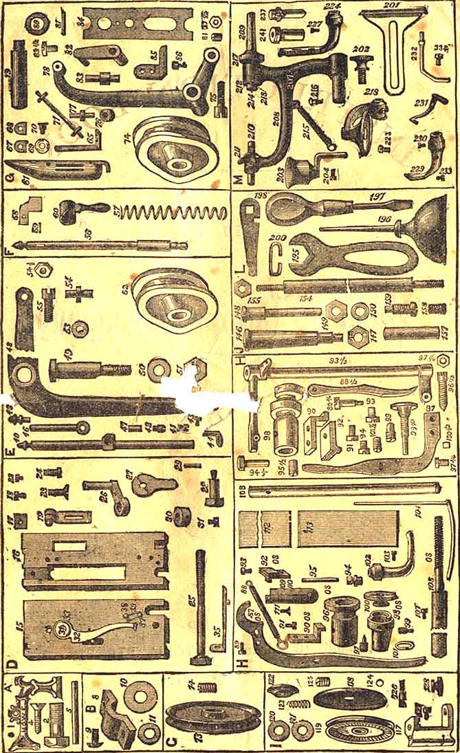
SECTION A1 Arm -- A, B, C.2 Arm Screw3 Arm Plate -- A, B, C.4 Arm Plate Screw5 Arm Spool Pin6 Bed (Step Feed) -- A, B, C.7 Bed (Wheel Feed) -- A, B, C.SECTION B8 Shaft Cap9 Shaft Cap Screw10 Bed Plate Washer (5/8 by 3/4)11 Bed Plate Washer (3/8 by 1/2)SECTION C12 Pulley -- A, B, or C.14 Pulley Screw -- A, B, or C.SECTION D15 & 16 Outside and Inside Face Plate -- A, B, or C.17 Presser Bar Guide Adjuster18 Presser Bar Guide Adjuster Screw19 Thread Controller -- Complete20 Thread Controller Plate21 Thread Controller Bridge22 Thread Controller Screw23 Inside Face Plate Screw24 Outside Face Plate Screw25 Presser Screw26 Presser Slide27 Adjusting Cam28 Adjusting Cam Screw29 Dowel Pin30 Presser Screw Boss31 Presser Screw Boss Screw31 1/2 Take Up -- Complete32 Take Up33 Take Up Spring34 Take Up Spring Screw35 Take Up Adjuster36 Take Up Adjuster Pin37 Thread Guide Pin38 Thread Guide Pin -- (Drilled)39 Thread Guide Pin WireSECTION E40 Needle Bar -- A, or C.41 Needle Bar Set Screw42 Needle Bar Thread Shield43 Needle Bar Thread Guide -- Upper44 Needle Bar Thread Guide -- Lower45 Needle Bar Thread Guide Screw46 Needle Bar Piston47 Needle Bar Piston Pin48 Needle Lever -- A, B, C, D.49 Needle Lever Stud -- A, B, C, D.50 Needle Lever Stud Washer51 Needle Lever Stud Nut52 Needle Cam -- A, B, C, D.54 1/2 Shuttle Lever -- A, B, C, D.55 Needle Cam ScrewSECTION F56 Presser Bar -- A, or C.57 Presser Bar Spring58 Presser Bar Guide59 Presser Bar Guide Pin60 Presser Bar LifterSECTION G61 Shuttle -- A, or C. -- Complete62 Shuttle Shell63 Shuttle Tip64 Shuttle Butt65 Shuttle Latch66 Shuttle Latch Rivet67 Shuttle Tension Plate -- Upper68 Shuttle Tension Plate -- Lower69 Shuttle Tension Spring70 Shuttle Tension Screw71 Bobbin -- A, B, or C.72 Bobbin Wire73 Bobbin Head74 Shuttle Cam -- A, B, or C.75 Shuttle Cam Screw76 & 77 Shuttle Cam Roll & Stud A, or C.78 Shuttle Lever -- A, B, or C.79 Shuttle Lever Stud -- A, or C.80 Shuttle Lever Stud Collar81 Shuttle Lever Stud Screw82 Shuttle Driver Link -- A, or C.83 Shuttle Driver Stud -- (Drilled)83 1/2 Shuttle Driver Stud Screw84 Shuttle Driver Slide85 Shuttle Driver86 Shuttle Driver ScrewSECTION H87 Feed Lever -- New or Old Style88 Feed Lever Spring -- New or Old Style88 1/2 Swing Lever88 3/4 Swing Lever Screw89 Feed Lever Spring Pin90 Feed Lever Rider -- New or Old Style91 Feed Lever Rider Screw -- New Style92 Feed Surface -- New or Old Style93 Feed Surface Screw -- New or Old Style93 1/2 Feed Rocker94 Feed Rocker Screw94 1/2 Feed Rocker Piston95 Feed Lever Pin95 1/2 Feed Rocker Piston Screw96 Lift Cam96 1/2 Feed Rocker Centre Screw97 Lift Cam Screw97 1/2 Feed Rocker Centre Nut97 3/4 Feed Lever Rider Screw98 Feed Cam -- New or Old Style99 Feed Cam Screw -- New or Old Style100 Feed Cam Nut100 1/2 Stitch Brake101 Feed Cam Nut Spring101 1/2 Stitch Brake Screw102 Presser Foot103 Presser Foot Screw104 Quilting Gauge105 Quilting Gauge Bar106 Quilting Gauge Plate107 Quilting Gauge Screw108 Shaft -- A -- New or Old Style108 Shaft -- B, or C109 Throat Plate -- Large Hole -- A, or C110 Throat Plate -- Small Hole -- A, or C111 Throat Plate Screw112 Shuttle Race Cover -- Back -- A, or C113 Shutle Race Cover -- Front -- A, or C114 Shuttle Race Cover Rivet115 Shuttle Race Cover PadSECTION I116 Tension -- Complete117 Tension Stand118 Tension Back Plate119 Tension Wheel120 Tension Washer -- Back121 Tension Washer -- Front122 Tension Nut Washer123 Tension Check Spring124 Tension Check Spring Washer125 Tension Check Spring Screw |
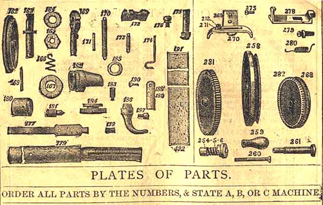
SECTION I (Continued)126 Tension Check Spring Screw Stud127 Tension Set Screw128 Tension Thumb NutSECTION J129 Table Top130 Drawer131 Drawer Slide, or Bolt132 Drawer Slide Screw134 Right Leg135 Left Leg136 Leg Screw137 Leg Brace142 Leg Brace Screw, No. 12, 1/2 inch143 Leg Brace Screw, No. 20, 5/8 inch144 Driving Wheel146 Driving Wheel Stud147 Driving Wheel Stud Nut148 Crank Pin149 Crank Pin Nut150 Crank Pin Washer151 Wheel Guard152 Wheel Guard Screw153 Pitman154 Treadle Rod -- A, B, or C155 Treadle Rod Nut156 Treadle156 1/2 Treadle Cone157 Treadle Pin158 Treadle Pin Screw159 Treadle Screw159 1/2 Treadle Cone Screw160 Dripper -- A, B, or C161 Dripper ScrewSECTION KWHEEL FEED PARTS162 Feed Wheel163 Feed Wheel Stud164 Feed Wheel Stud Washer165 Feed Wheel Nut166 Feed Wheel Stud Spring167 Feed Clutch Lever Washer168 Feed Stud Pin169 Feed Clutch Lever170 Feed Clutch Lever Spring171 Feed Clutch Lever Spring Pin172 Feed Clutch173 Feed Clutch Spring174 Feed Clutch Spring Hook175 Feed Rider176 Feed Rider Screw177 Feed Brake178 Feed Brake Screw179 Shaft -- A, B, or C180 Shaft Collar181 Feed Cam182 Feed Cam Screw184 Feed Cam Nut185 Feed Cam Nut Spring186 Presser Foot187 Presser Foot Screw188 Throat Plate -- Large Hole189 -- Throat Plate -- Small Hole190 Throat Plate Screw191 Shuttle Race Cover -- Back192 Shuttle Race Cover -- Front193 Shuttle Race Cover Rivet194 Shuttle Race Cover PadSECTION L195 Wrench196 Oil Can197 Screw Driver198 Shuttle Screw Driver199 Belt200 Belt HookSECTION M201 Gauge202 Gauge Screw203 Oil Cup204 Oil Cup Set Screw205 Spooler -- Complete208 Spooler Frame209 Spooler Spindle210 Spooler Step211 Spooler Thumb Screw212 Spooler Spindle Washer213 Spooler Spindle Washer Pin214 Spooler Spindle Driving Pin215 Spooler Spring216 Spooler Spring Pin217 Rubber Ring218 Roll Presser219 Roll Presser Arm220 Roll Presser Arm Stud221 Roll Presser Stud Nut222 Roll Presser Wheel223 Roll Presser Set Screw224 Foot Hemmer - Nos 1, 2, or 3225 Bed Plate Hemmer226 Hemmer Tongue227 Hemmer Set Screw228 Braider -- Complete229 Braider Foot230 Braider Foot Screw231 Braider Spring232 Braider Spool Pin233 Braider Spring Screw234 Braider Spool Pin Screw235 Spool Pin Stop235 1/2 Corder -- Complete237 Bed Hinge238 Bed Hinge Rivet239 Bed Hinge Stud240 Bed Hinge Stud Pin241 Bed Hinge Stud RubberCABINET FIXTURES246 Treadle Bracket249 Wheel Guard255 HangerHAND MACHINE258 Hand Wheel259 Handle260 Handle Stud261 Hand Wheel Stud262 Hand Wheel Stud Screw264 Eccentric Nut Pin265 Eccentric Nut Spring266 Eccentric Nut268 Pulley269 Shuttle Carrier270 Shuttle Carrier Spring271 Shuttle Carrier Spring Washer272 Shuttle Carrier Spring Screw273 Shuttle Carrier Screw275 Shuttle Race -- Old Style276 Shuttle Race Screw278 Bed Plate Latch279 Bed Plate Latch Screw280 Bed Plate Latch Spring281 Large Geared Wheel282 Small Geared Wheel |
INDEX
To learn to use the Machine and Attachments, proceed in the following order:
To Place the Machine on the Table ---- Page 6
To Oil the Machine ----- 7
To Work the Treadle ---- 8
To Wind the Bobbin ---- 9
To Thread the Shuttle ---- 10 & 11
To Thread the Machine ---- 12
To Oil the Tension ---- 13
To Place the Shuttle in the Machine ---- 14
To Draw up the Lower Thread ---- 15
To Regulate the Length of Stitch ---- 15
To Change and Set the Needle ---- 16
Missing Stitches ---- 17
To Regulate the Tensions ---- 18
Commencing to Sew ---- 19
To Remove the Work from the Machine ---- 20
To take off the Presser Foot ---- 21
To learn to use the Attachments:
To adjust and work with the Narrow Hemmer ---- 22 & 23
To make a Fell ---- 24
To Braid ---- 25
To Quilt ---- 26
The wide Bed Plate Hemmer ---- 27
Instructions for Hand Machine ---- 28 & 29
Instructions for Wheel-feed Machine ---- 30 & 31
Remarks on Needles and Thread ---- 32
~~~~~~~~~~~~~~~~~~~~~~~~~~~~~
TO THE LEARNER
A LITTLE time given to the study of the instructions, before commencing to use the machine, will be found of great advantage.
The working of the machine is explained as minutely as possible, and each operation made the subject of illustration. The cute are arranged in the order in which the learner must proceed.
A careful examination of the illustrations alone will be sufficient to teach the most inexperienced to operate successfully.
Never attempt to take the machine apart, or you will be sure to bet into trouble.
Become perfectly familiar with the machine before undertaking any practical work.
If the Machine miss stitches, see that the needle is properly set, and that the thread and needle are of the proper size to be used together.
If the thread breaks, be sure that the needle is not too high, and that the short groove is next to the shuttle, and that the machine is threaded properly, and that the tensions are not too tight, and that the eye of the needle is not sharp.
When about to sew thick, soft material, adjust the machine for a longer stitch.
Part Two
Part Three
Part Four
Part Five
Part Six
Part 2
THE NEEDLEBAR Archive at ISMACS International
Online Manuals Section
Manual supplied courtesy of Jenny Sims-Veale
INSTRUCTION BOOK
.Part Two
TO PLACE THE MACHINE ON THE TABLE
Fig. 1
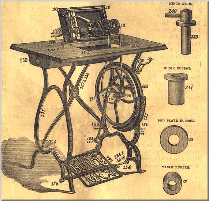
Enter the hinge rubbers No. 241 into holes in back part of table at 241. Enter table rubbers No. 11 into holes No. 11 in front part of table.
Place Bed Plate Rubbers No. 10 on the pins No. 10 on the front corners of the machine. Attach hinges No. 239 (see Fig. 2, page 7), to the machine, and enter them into the rubbers No. 241 in the table; turn the machine down, as shown in Fig. 3, page 8; pas the belt around the groove of the driving wheel No. 144 and pulley Np. 13, sufficiently tight to drive the machine.
The belt should be thrown off when machine is not in use, and if it becomes too loose to drive the needle through heavy goods, shorten it by cutting about half and inch off one end where it is joined together, punch a new hole, and fasten as before.
OILING THE MACHINE
Fig. 2
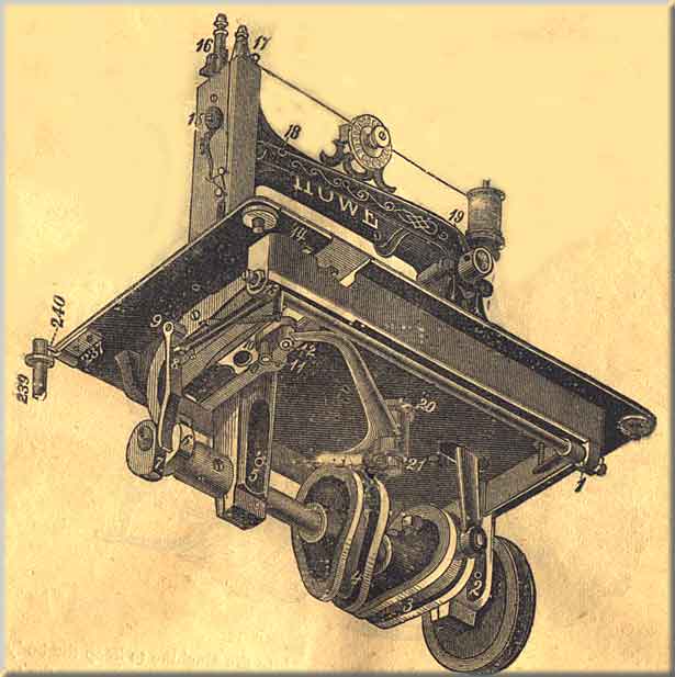
Slip the belt off driving-wheel No. 144, turn the machine back on its hinges, as shown in Fig. 1, page 6, oil all the bearings indicated by the numbers, beginning with No. 1, taking the figures in their regular order, 1, 2, 3, 4, and so on to 21. In this way you will be sure to find every place requiring oil, and avoid oiling the same place more than once. To oil the stand, commence at No. 1, Fig. 3, page 8, taking the numbers in their regular order to No. 6. Care should always be taken, before commencing to operate, that the running parts are well cleaned and oiled. No part can be permitted to run dry without detriment to the machine.
NOTE -- Use good oil -- pure sperm is the best. Poor oil will gum, and cause the machine to run heavily. Spirits of turpentine or kerosene oil will be found useful in cleaning the machine after using bad oil.
TO WORK THE TREADLE
Fig. 3
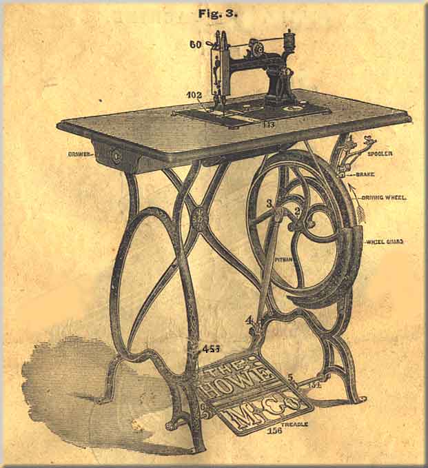
Take the belt off; place the chair near enough to the machine to keep the body erect while operating. Place the feet on the treadle with the instep directly over the treadle-rod No. 154. Start the driving wheel No.144 from you in the direction of the arrow and keep turning by gently pressing on the treadle with the heel and toe alternately, until you have full control of the treadle motion.
To work the machine, remove the front slide 113, and take out the shuttle; raise the presser foot No. 102, by turning the handle 60 from you, put on the belt, start the driving wheel as before, and work the machine until you have become familiar with the motion. Without having the shuttle in or the machine threaded, place a piece of material under the needle; let the presser foot down by moving handle 60 toward you, aand run the machine with the presser foot down on the feed without having goods between them, and do not attempt to sew until you can turn the machine regularly, and start and stop it with ease. After becoming familiar with the motion and before proceeding to sew, clean both the machine and stand, and wipe all waste off from the lower end of the needle bar and out of the shuttle race.
TO WIND THE BOBBIN, WITH NEW TOP WINDER
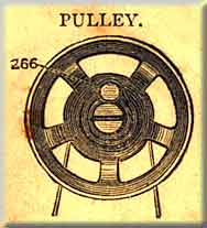
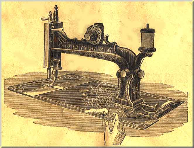
It is always advisable, when winding, to detach the large pulley from the small one by pulling out the eccentric nut pin, so that in working the treadle only the large pulley revolves; then press forward the winder, so that the rubber ring (217) presses on the large pulley.
Put the thread through the hole in the bobbin flange; then press the bobbin (71) against the spooler step, pressing it back to admit of the other end going into the hole in the spindle, and driving pin into the hole in the bobbin flange.
NOTE -- Never use glazed threads in the shuttle.
With this new winder, the spindle stem is put in with the accessories, so that it does not interfere with putting the half case on the machine when wanted; but when it is required to wind spools, the screw is taken out of the spindle and the end of the stem inserted.
The hand appliance wheel is not given with the machine, but is sold as an extra attachment, and when put on the machine, the winder must be moved, so that the rubber will press against the hand wheel, somewhat similar to the arrangement on the hand machine.
THREADING THE SHUTTLE
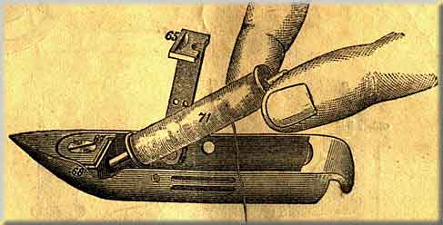
Fig. 6
TO PUT IN THE BOBBIN
Raise the latch No. 65, and hold the bobbin so that the thread will draw off from the under side, as shown in Fig. 6; enter one end into the small hole near the point of the shuttle; drop the other end into the heel, and close the latch, as shown in Fig. 7
Fig. 7
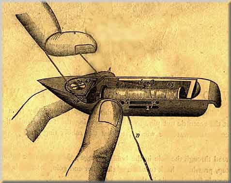
TO THREAD THE SHUTTLE
Pass the end of the thread "B" out through the bottom slot at No, 1, and back through the top slot at No. 2, thence through the top hole in the latch at No. 3, and back through the bottom hole in the latch at No. 4; hold the end of the thread "B" between the side of the shuttle and the finger at "A"; pass the loop thus formed between the tension plates at 68, and draw it around the tension screw No. 70, in the direction of the arrow, coming out between the plates at 67; draw up the slack, and pass the end of the thread "B" out through the hole in the side of the shuttle at No. 5. Be sure to have the thread between the tension plates 67 and 68, and not under them.
Fig. 8
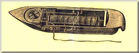
This shows the shuttle fully threaded, and so plain that if the learner will but follow the line of thread with the eye it will be impossible to make a mistake.
Except where a very delicate tension is required, omit threading through the slots at No. 1 and No. 2, as in Figs. 7 and 8, and thread as shown in Fig. 9.
Fig. 9
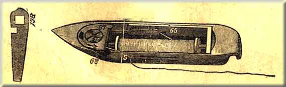
Have the thread leading from the under side of the bobbin, and out through the lower hole in the latch 65, and back through the top hole, thence between the tension plates and out through the side of the shuttle at 5, as shown in the cut.
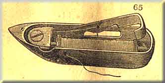
In order to further facilitate the threading of the shuttle, we are supplying with our hand, and some of our treadle machines, shuttles with a latch (No. 65), same as in Fig. above, whcih does away with passing the cotton through slots 1 and 2 and holes 3 and 4, as shewn in Fig. 8. Coarse glacé thread should not be used in this shuttle.
Part One
Part Three
Part Four
Part Five
Part Six
Part 3
THE NEEDLEBAR Archive at ISMACS International
Online Manual Section
Manual supplied courtesy of Jenny Sims-Veale
INSTRUCTION BOOK
.Part Three
TO REGULATE THE SHUTTLE TENSION
The tension screw No. 70 is a left hand screw, and operates the reverse of ordinary screws. With that the tension can be increased or lessened at pleasure. To increase the tension, turn the screw-driver No. 198, shown above.
To decrease the tension, turn the screw in the opposite direction.
TO THREAD THE MACHINE
Fig. 10
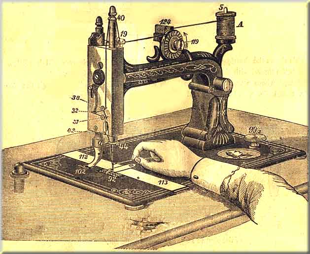
Fig. 11
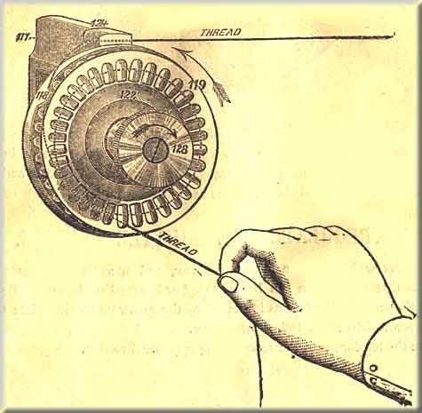
Use 60 cotton and a No. 1 needle in learning. Place the spool of cotton "A" on the spool-pin at No. 5, draw the thread into the slot at No. 124 in the top of the tension stand; thence into the V-shaped groove of the tension wheel at point 118 (see Fig. 11, page 12), and twice around the wheel in the direction indicated by the arrow; thence through the thread controller No. 19, and into the slot on the top of the needle bar No. 40, and downwards under thread guide-pin No. 38; thence through the hook on the end of the take-up No. 32, and back over thread guide-pin No. 37; thence through the curved hook No. 44 at the bottom of the needle bar, and lastly through the eye of the needle, as shown in Fig. 10, page 12.
Fig. 12
TO OIL THE TENSION
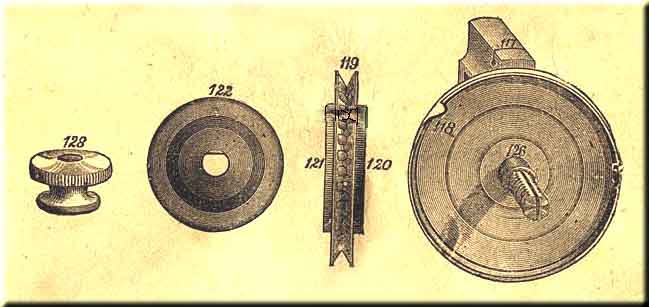
Take off the thumb nut 128, then the tension nut washer 122, and lastly the tension wheel 119, and put half a drop of oil on the screw stud directly at 126.
Great care must be taken to get no oil on the cloth washers 120 and 121 on the sides of the tension wheel.
In re[placing the wheel, always put the black cloth washer 120 back. To replace the nut washer 122, it will be observed that one side of the hole is flat, which must be put on to fit the flat side of the screw stud 126, then put on the thumb nut 128. Once a month is often enough to oil the tension.
TO PLACE THE SHUTTLE IN THE MACHINE
Fig. 13
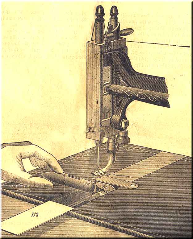
Raise the needle bar to its highest point, withdraw the front slide 113, take hold of the shuttle and slide the heel along on the bottom of the race, holding the point high enough to allow the hook on the heel to pass under the end of the driver No. 85; then let it drop into its place, as shown in Fig. 16, page 16.
NOTE -- Draw the thread through the eye of the needle and through the hole in the side of the shuttle, so as to leave the ends about three inches long.
TO DRAW UP THE LOWER THREAD
Fig. 14
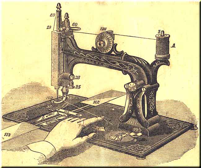
Withdraw front slide 113; hold the end of upper thread slack with the left hand; turn the driving-wheel with the right hand until the needle passes down.
If the needle is set properly a loop will be formed by the upper thread in the shuttle race (see Fig. 16, page 16), through which the shuttle will pass, and the needle, in its ascent, will draw the lower or shuttle thread up through the hole in the throat plate No. 109.
Part One
Part Two
Part Four
Part Five
Part Six
Part 4
THE NEEDLEBAR Archive at ISMACS International
Online Manuals Section
Manual supplied courtesy of Jenny Sims-Veale
INSTRUCTION BOOK
.Part Four
TO REGULATE THE LENGTH OF THE STITCH
Near the right hand end of the bed plate of the machine will be found the stitch thumb screw No. 99 1/2, as shown above. To lengthen the stitch, turn the thumb screw to the right, thus,
 .
.
To shorten the stitch, turn to the left, thus,

Fig. 16
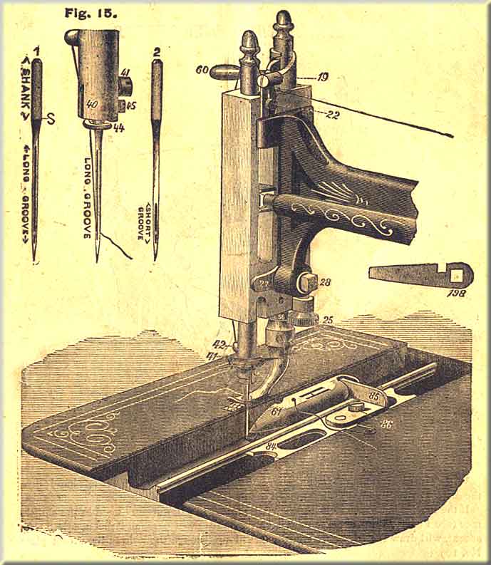
TO REMOVE THE NEEDLE
Raise the needle bar to its highest point, lift the presser foot and turn it back out of the way, loosen the screw No. 41, and remove the needle.
TO SET THE NEEDLE
Hold the needle between the thumb and the index finger of the left hand, and pass the point down through the needle hole in the throat plate; then enter the shank of the needle in the hole in the lower end of the needle bar, and push the needle up until the lower part of the shank at S (Fig. 15, page 16) is even with the lower end of the needle bar, and fasten it in its place with the screw No. 41.
Be very careful to have the short groove of the needle next to the shuttle; remove both slides Nos. 112 and 113 (see Fig. 14, page 15); thread the needle from left to right, so that the thread will run across the centre of the throat plate, as shown in Figs. 10 and 14, pages 12 and 15; turn the driving-wheel from you until the needle descends to its lowest point.
By continuing this movement the needle will raise about one-eighth of an inch, at the same time throwing out a loop of thread squarely into the shuttle race, through which the shuttle will pass.
If your needle is set right, the bottom of this loop and the eye of the needle will be even with the bottom of the shuttle race, as shown in Fig. 16, page 16. For fine thread, the needle may be set a trifle higher, until the point of the shuttle enters the largest part of the loop.
MISSING STITCHES
If the needle is improperly set it may throw the loop to one side, so that the shuttle will pass by instead of through the loop. To prevent this, turn the needle in opposite direction until it throws the loop full into the shuttle race. Sometimes the machine will miss stitches because the needle sets too far from the shuttle, and at other times the shuttle will strike the needle because the needle sets into the shuttle race.
To adjust the needle nearer to or further from the shuttle, place the wrench 198 (Fig. 16, page 16) on the head of the screw No. 28, and press it downwards; this will loosen the screw, so that the head of the machine can be moved.
To adjust the needle nearer to the shuttle, move the end of the adjusting cam (27) up and then turn the screw (28) back into its place.
To adjust the needle farther from the shuttle, move the adjusting cam (27) downwards and tighten the screw, as before. The needle should set as near the shuttle as possible without striking it.
NOTE -- The adjustment referred to above is only necessary in changing from fine to coarse needles.
TO REGULATE THE TENSIONS
Before commencing to sew, always be careful to have some tension upon each thread. Try them with the hand to see that they pull as nearly alike as possible.
If the threads are of the proper size,
having the right and equal amount of tension upon them, they will be drawn and
locked together in the centre of the material, thus  If
the shuttle tension is tight and the upper tension too loose, the under thread
will lie straight, thus,
If
the shuttle tension is tight and the upper tension too loose, the under thread
will lie straight, thus,  .
On the contrary, if the upper tension is tight and the lower tension too loose,
the upper thread will lie straight, thus,
.
On the contrary, if the upper tension is tight and the lower tension too loose,
the upper thread will lie straight, thus,  .
Therefore, in order to make a perfect stitch on both sides of the material,
it is necessary to have the tensions as nearly equal as possible, and tight
enough only to make a firm seam without breaking the threads.
.
Therefore, in order to make a perfect stitch on both sides of the material,
it is necessary to have the tensions as nearly equal as possible, and tight
enough only to make a firm seam without breaking the threads.
To tighten the tension on the upper thread,
turn the tension thumb nut 128 to the right, thus,
To loosen it, turn to the left, thus,
To tighten the lower or shuttle tension, turn the small screw No. 70, near the point of the shuttle,
to the left, thus,
To loosen, turn it to the right, thus,
In changing the shuttle tension, which is seldom necessary, turn the screw but very little.
NOTE -- Remember the shuttle tension screw No. 70 is a left hand screw, and operates the reverse of ordinary screws.
NOTE -- In sewing heavy garments, they must be held so as not to pull back on the feed, or the stitches will be irregular.
When the machine is in operation, do not pull upon the goods so as to bend or break the needle.
Fig. 17
COMMENCING TO SEW
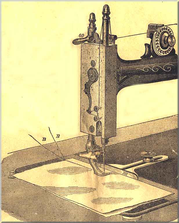
The machine being fully threaded, both above and below, the shuttle thread drawnup through the throat plate 109, the needle bar and presser foot both at their highest point, slacken the thread, as shown at A, Fig. 18, page 20, and draw it through the eye of the needle, so as to leave an end about two or three inches long. Draw the shuttle thread up through the throat plate about the same distance, pass the two ends BB under the presser foot towards the back part of the machine, as shown in Fig. 18.
Attach the gauge No. 201 to the bed plate of the machine by means of the screw under the needle far enough to the right to make a seam of the proper width.
Let down the presser foot upon the work, move up the gauge to the edge of the goods, and fasten it there with the thumb screw No. 202; start the machine, holding the ends of the threads down until two or three stitches have been taken; then remove the hand from the threads and proceed with the sewing, the goods being kept even with their edges against teh gauge. If the tensions are right, the stitch will be alike on both sides of the material.
Fig. 18
TO REMOVE THE WORK FROM THE MACHINE
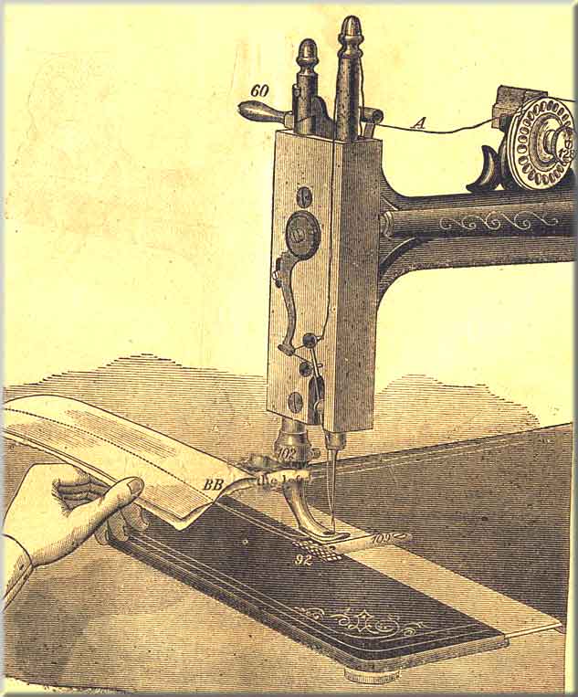
On reaching the end of the seam, stop the machine, with the needle at its highest point.
Take hold of the thread at A and slacken it, by drawing about two inches off from the spool, raise the presser foot, take hold of the work, raise it up and draw it gently from you towards the back of the machine, keeping the upper thread in the notch in the presser foot to avoid bending the needle, as shown above. Cut the threads about two inches from the needle.
NOTE -- If the shuttle thread should break in taking the work out, it will be an indication that the shuttle tension is too tight, and should be loosened a little.
Part One
Part Two
Part Three
Part Five
Part Six
Part 5
THE NEEDLEBAR Archive at ISMACS International
Online Manuals Section
Manual supplied courtesy of Jenny Sims-Veale
INSTRUCTION BOOK
.Part Five
Fig. 19
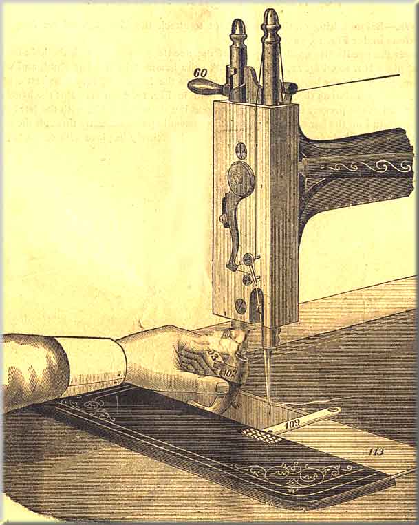
TO TAKE OFF THE PRESSER FOOT
Remove the back shuttle race cover No. 112; turn the handle of the lifter No. 60 back until it points straight from you, as shown above. Loosen screw No. 103, turn the presser foot back, and take it off directly into the shuttle race.
To put the foot on, hold it in the same position as shown above.
NOTE -- The above rule must be strictly observed in both taking off and putting on the Hemmer, Braider and Corder. The object in lowering them into the shuttle race is to avoid scratching the japan and defacing the bed of the machine.
TO ADJUST THE HEMMER
NOTE -- Before taking off the presser foot to attach the Hemmer, read carefully the directions under Fig. 19, page 21.
Lower the needle bar until the point of the needle passes through the hole in the throat plate No. 109, Fig 21, page 23. Take the hemmer in the left hand, and with the large screw-driver loosen screw No. 227, pass the lower end into the shuttle race in the same position as the presser foot is held in Fig. 19, page 21. Put the hemmer on the end of the presser bar, and work it up to the shoulder at 56; with the left hand pull it around on the bar towards you until the needle passes directly through the centre of the needle hole in the Hemmer, and fasten it securely in place with screw 227.
Fig. 20
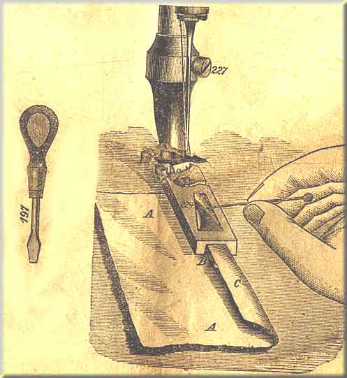
TO COMMENCE HEMMING
Turn over the edge of the material and crease it down about two inches in length. as shown above; enter it into the hemmer, having the material, A A, pass under the hemmer foot, and the fold or creased edge C into the hemmer, over the blade B. Use a pin in assisting to enter the material into the hemmer and passing it along the blades to the needle.
Pull the handle of the lifter No. 60 towards you, letting the hemmer down on the material, and start the machine.
Fig. 21
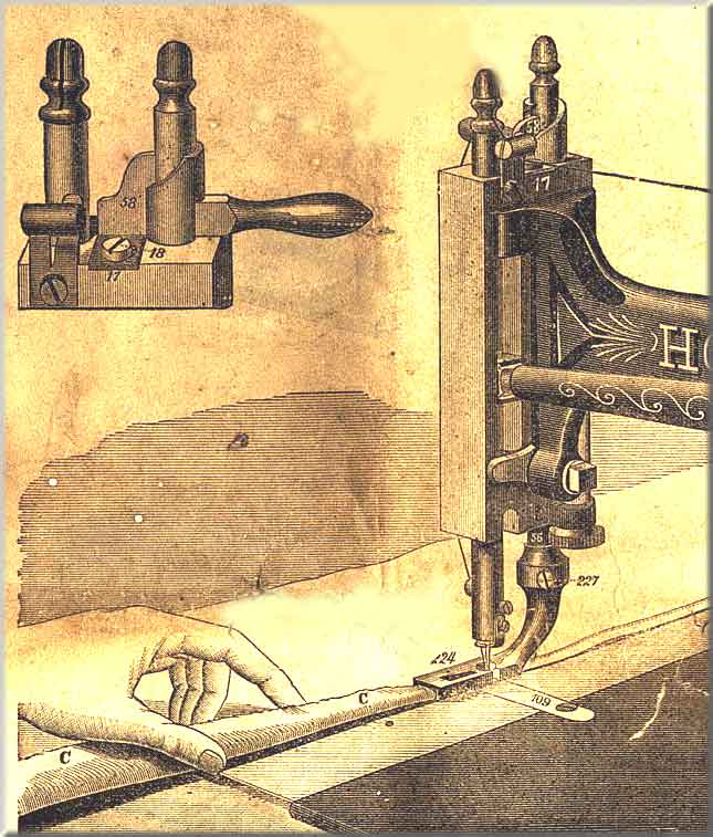
HEMMING
With the left hand fold the edge of the material and guide into the hemmer just enough to fill the channel, as shown above, holding back on the material gently to keep it straight.
If too much material is fed into the hemmer it will be crowded out under the right hand edge, thus laking a wide and irregular hem, and if not enough the raw edge will not be turned under. If the stitching is too far from the edge of the hem, loosen screw No. 227, and turn the hemmer a little to the right; if too near the edge, turn it a little to the left. When the hemmer is properly adjusted fasten it firmly with the screw No. 227. If the presser bar guide No. 58 becomes loose, allowing the hemmer to work sideways, loosen screw No. 18, and move up adjuster No. 17 close against the guide No. 58 and titghten the screw.
NOTE -- In removing the work from the hemmer, always take it out from you towards the back part of the machine, as hsown in Fig. 18, page 20. If you pull it out towards you, you will be liable to ruin the hemmer.
Fig. 22
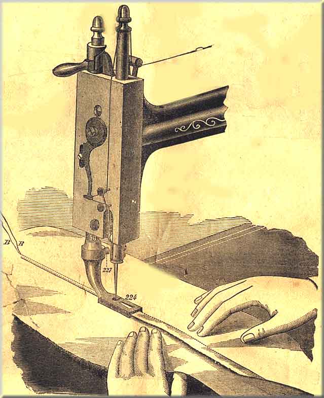
TO MAKE A FELL
Place the two pieces of material to be felled under the hemmer, and let it down upon them; have the edge of the lower piece project about an eighth of an inch beyond the edge of the upper; stitch them together, guiding the edge of the upper piece by the right hand edge of the hemmer at 224. On reaching the end of the same pull the work out, as shown in Fig. 18, page 20; cut the threads, leaving ends about three inches long attached to the material, as shown at B B.
Trim the edges, if necessary, as in hand felling, the upper one as close as it will bear with safety, leaving the under one just wide enough to fill the hemmer, as shown in Fig. 20, page 22.
Open out the goods, turn the wide edge over to the left and crease it down, holding the material in the left hand, raise it up a little, take hold of the two threads B B, and draw the edge to be felled into the hemmer over the blade B as far as the needle, and let down the hemmer upon the work, and start the machine. Pull gently on the threads B B until two or three stitches have been taken.
Keep the cloth smooth and guide it into the hemmer, as shown above. Be sure to draw the work from you when removing it, as shown in Fig. 18, page 20.
NOTE -- Never attempt to fell coarse, heavy goods with this hemmer.
Fig. 23
BRAIDING
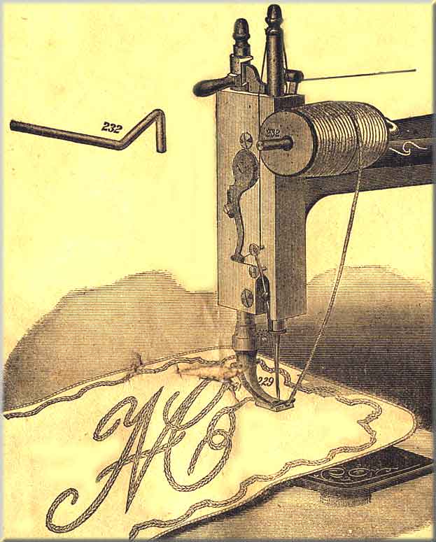
Have the needle at its highest point; attach the Braider Foot No. 229 in place of the presser foot; be careful to have the needle pass through the centre of the needle hole in the braider. Insert the short end of the braider wire No. 232 in the hole in the presser arm, as in Fig. 26, page 28, and fasten it with the set screw in the back part of the arm.
Place the spool of braid on the long end of the wire No. 232; pass the braid under the end of the spring No. 231, and down through the needle hole in the foot, letting the end extend back from the under side of the foot, as shown above; start the machine, guiding the material according to the pattern already marked out. In turning square corners, have the needle about half way down.
NOTE -- The following fixtures, viz.: a Gauge, Thumb-Screw, twelve Needles, six Bobbins, one Wrench, Oil-Can filled with Oil, Screw-Driver, Shuttle Screw-Driver, an extra Needle or Throat-Plate, a narrow Hemmer (which is also a Feller), a Braider, and Quilting Gauge, go with each family machine -- also with the step feed B and step feed C machines -- free of charge.
Fig. 24
QUILTING
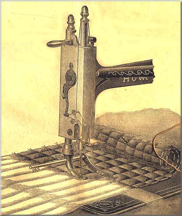
To attach the quilting gauge, put the quilter bar No. 105 through the hole in the presser foot, as shown above, and fasten it in place with screw No. 107 in the back part of the presser foot.
Adjust it to the right or left, according to the distance required between the lines of stitching, and just far enough above the bed of the machine to allow the work to pass under freely.
The fiest line of stitching should pass through the centre of the goods, and from this line work both ways towards the edge.
Part One
Part Two
Part Three
Part Four
Part Six
Part 6
THE NEEDLEBAR Archive at ISMACS International
Online Manuals Section
Manual supplied courtesy of Jenny Sims-Veale
INSTRUCTION BOOK
.Part Six
ATTACHMENTS &c.,
ADAPTED TO THE HOWE SEWING MACHINE
----------------------------------
BED PLATE HEMMER
We have several sizes which are used chiefly for sheeting, table cloths, and material generally of this description. In ordering there hemmers, the size of them should be mentioned.
We also make an adjustable hemmer, which can be adjusted to make hems of any size up to an inch.
INSTRUCTION -- Leave the ordinary presser foot on the machine, raising it from the feed. Attach the hemmer to the bed of the machines by means of the gauge screw No. 202 (some of the larger sizes are fastened with two screws). Enter the edge of the material in the hemmer so as to fill the scroll; work it forward and back a little until the hem is turned evenly; let the presser foot down, being careful not to disarrange the hem; start the machine, and guide the material so as to keep the scroll filled.
These hemmers are charged extra.
BINDERS
We have several kinds, adapted for different descriptions of work, such as dressmaking, tailoring, hat binding, &c. In ordering, the purpose for which it is required should be stated.
Binders are charged extra, and instructions sent, if required.
CORDER
This is a special attachment, and is charged extra. We give instructions fot the description of corder most generally used.
INSTRUCTIONS -- Fold the material and crease it down, pass one edge of the material under and the other over the corder blade, so that the end of the corder blade will be between the cloth and close against the crease, and let down the foot upon the work. In stitching in the forst cord, guide the work slightly to the left, so as to lay the cord close into the crease, keeping the work smoothly in front of the needle, the cord passing through the left hand groove in the bottom of the corder foot. Stitch the second cord in close against the first by guiding the work slightly to the left, as before.
Make the stitch rather longer than in ordinary sewing, and in turning square corners have the needle down.
This attachment will be charged for extra.
RUFFLER
We now give this attachment with each step-feed machine.
INSTRUCTIONS -- Place the pin through the hole in the presser foot, and secure it by the screw No. 107. The material to be gathered or ruffled is then put under the ruffler, so as to rest on the feed. The band, if one is to be sewn on at the same time, must be placed between the opening in the ruffler, and should be held a little tightly with the hand, It is necessary to lengthen the stitch and loosen the tension.
NOTE -- The following accessories, viz.: A gauge, thumb-screw, twelve needles, six bobbins, one wrench, oil-can, screw-driver, shuttle screw-driver, an extra needle or throat-plate, a narrow hemmer (which is also a feller), a braider and quilting gauge, go ith each family machine -- also with the step feed B and step feed C machines -- free of charge.
--------------------------------------
HALF CASES
The Half Case is useful for preserving the machine from dust, and for preventing its improper use; at the same time it forms a handsome piece of furniture. Price 20s.
BOXES FOR HAND MACHINE
For preserving the machine, and for facility in transport.
Plain, 5s.; Polished, 10s.; Black Walnut, 15s.
THE HOWE HAND MACHINE
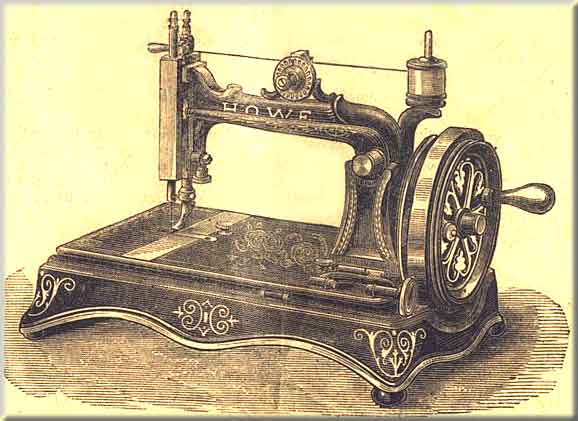
This illustration shows the Howe Hand Machine, with all the latest improvements. The machine as above can be placed on a stand, and the belt can either be put in the groove on the large hand wheel, which gives a very easy motion; or the belt may be put on the small pulley on the shaft, which gives greater speed -- an essential in very light work -- but not quite the same power.
If the purchaser requires the machine to work by treadle only, and not by hand, a hole can be cut in the table top, and the machine placed therein, the same as the A and B machines.
The construction of the machine is so perfect that it will do what may be considered light, and also heavy work fr a hand machine, but we do not recommend this machine to be kept constantly on very heavy work.
To prevent the liability, when moving the machine, of having the head drop from the base, we sometimes put a screw into the bed-hinge stud (239) with a washer, which perfectly secures the bed of the machine to the base. This is not actually essential, but is found serviceable when perfect security is required against the possibility of accident.
Nearly all the parts of the Howe Hand Machine are similar to those of the A and B machines. Some are smaller, but the same in principle and action; therefore in giving instructions we only touch on those points which are on this machine and not on the others.
TO WIND THE BOBBIN
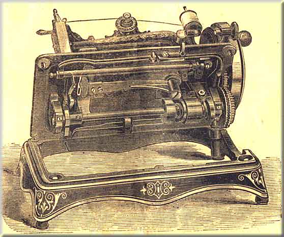
Pull out the nut on the side of the wheel, turn it hal way, so as to free the pin from the large geared wheel, thus allowing the hand wheel to revolve without turning the machine; then lift the winder, so that it will press against the wheel; and place the bobbin according to the instructions given in page 9. When finished pull the winder to the right, and it will fall and rest upon the bed plate. Replace the nut, so that the hand wheel is connected with the geared wheel, and the machine is ready to work.
The Shuttle Lever (78) is different in form at the end from the lever of the A, B and C. The two holes in the end are made oblong, so that the shuttle-carrier can be adjusted either nearer to or farther from the shuttle race, as may be found necessary.
In putting the shuttle into the machine, care should be taken not to destroy the spring (277) at the back of the shuttle-carrier, which is put there for the purpose of pressing the shuttle against the face of the race; should the spring become broken, the shuttle would be liable not to catch the loop of the thread, and therefore not pass through.
TO OIL THE MACHINE
Press the spring of the latch to the right, and turn the machine over on its hinges. Oil all the bearings, and follow instructions given in page 7.
ATTACHMENTS AND ACCESSORIES
All attachments and accessories which can be used upon our Family Machines for braidning, hemming, felling, &c., may be applied to this machine.
INSTRUCTIONS FOR THE WHEEL-FEED MACHINE
Instead of the above top tension (No.116), the old style flat tension, which is adjusted by a set screw, can be supplied if desired.
TO LENGTHEN OR SHORTEN THE STITCH OF THE WHEEL-FEED MACHINE
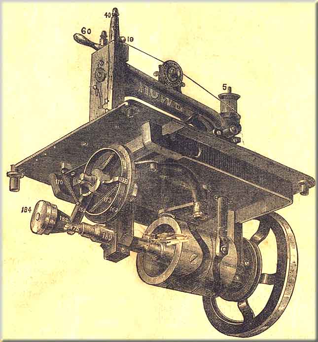
On the end of the shaft of the machine is a conical cam (182), against which the feed rider (175) rests. Connected with this cam is a thumb nut (184). By turning this nut so that the cam (182) will be moved on to the shaft, the stitch will be lengthened; and by reversing this nut so that the cam is moved towards the end of the shaft, the stitch will be shortened.
On the "C" machine the conical feed cam (No.182) is much larger than on the "B", which enables the operator to make a much longer stitch; but if specially ordered this larger cam could be adjusted to the "B" machine, where work with a very long stitch is required.
TO RAISE OR LOWER THE FEED
To Raise the Feed -- loosen the nut (165), on the feed-wheel stud (163), and press the feed-wheel (162) upwards, and tighten the nut again firmly in its place. For ordinary dewing, the teeth of the feed-wheel should rise about 1/32 of an inch above the top of the needle plate. When using the machine for leather binding, or on thick wadded fabrics, the teeth should come up about 1/20 of an inch above the needle plate.
To Lower the Feed -- loosen the nut as before, and the feed-wheel will drop downwards as far as you wish. When it is in proper position, tighten the nut as before.
The feed-clutches (172) should be kept well oiled to prevent wear, and also to make them work evenly and securely.
Care should be taken that the feed-rider (175) works freely in the feed-clutch lever (169), so as not to cut the feed-cam (182).
The feed-brake (177) should at all times rest firmly on the feed-wheel.
THE ROLL PRESSER
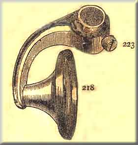
Take the flat presser foot off and fasten the roll presser (218) to the presser bar; let the edge of the roll presser be close to the needle hole, and fasten it securely to the presser bar by screws (223).
This attachment is given with every wheel-feed machine, and is used in place of the flat presser when stitching heavy material.
THE FOLLOWING ACCESSORIES ARE SENT WITH EACH WHEEL-FEED MACHINE:
Roll Presser, Flat Presser, Tucking Guide and Screw, Six Bobbins, Twelve Needles, Two Screw Drivers, Wrench, Oil Can, and ectra Throat Plate.
All the parts of the wheel-feed machines are the same as those of the step-feed machines, except the parts as numbered and named in the plate of parts section K.
~~~~~~~~~~~~~~~~~~~~~~
Part One
Part Two
Part Three
Part Four
Part Five