All 4 available source parts are included below.
Part 1
THE NEEDLEBAR Archive at ISMACS International
Online Manuals Section
Singer 201k Instruction Manual (post-1954)
Part One
LIGHT
 To
Turn Light "on" or "off"
To
Turn Light "on" or "off"
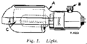
To turn on light, reach over machine arm and turn switch B, Fig 1 clockwise. To extinguish light turn switch anticlockwise.
To Remove Bulb
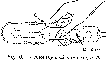
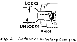
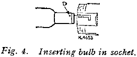
Grasp light socket so that thumb extends over switch B. Press shade with thumb at A to release shade from two catches, and slide it halfway out if shade holder C. Press bulb into socket and at the same time turn bulb over from mchine as far as it will go to unlock pin D (see Figs 3 and 4). Withdraw the bulb.
To insert New Bulb
Press bulb into socket and turn it over toward machine until pin D enters notch in socket (see Fig 3). Return shade to its normal position as shown in Fig 1.
IF MACHINE IS ELECTRICALLY OPERATED
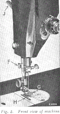
Raise presser foot G by means of presser bar lifter J to prevent injury to the foot G and feed H.
Place a piece of material under presser foot and let the foot down upon it. Turn on electric current and, if the combination knee and foot controller is installed as a knee controller, press knee lever to the right.
If controller is placed on the floor to be used as a foot controller, press down on pedal of controller.
The speed of the machine is controlled entirely by the amount of pressure applied to the controller.
Operate the machine in this way, without being threaded, until you have become accustomed to guiding the material and operating the controller.
IF THE MACHINE IS HAND OPERATED
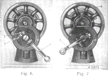
When the machine is uncovered, the hand attachment will be gound to be out of working position as shown in Fig 6. Pull the small spring stud 2, and trun the handle back until the lever 1 enters the socket 3. Press back the hinged finger 4, Fig 7 between the spokes of the wheel. The machine is now ready for working, as shown in Fig 7.
TO OPERATE THE HAND MACHINE
Place a piece of material under the presser foot G, Fig 5, and lower the latter by means of the lifter J.
Now turn the handle over from you to work the machine, without being threaded, until you are accustomed to guiding the material with the left hand.
IF THE MACHINE IS TREADLE OPERATED
Loosen the hand wheel by turning stop motion screw 17, Fig 12, over toward you, place both feet upon the treadle and turn the hand wheel over toward you, at the same time allowing the feet to move freely and lightly with the motion of the treadle.
Continue to do this until a regular and easy movement is acquired and you are able to work the treadle so that you can re-start the machine with the wheel turning toward you.
When familiar with the working movement, tighten the hand wheel by turning the stop motion screw over from you, and place a piece of material under the presser foot G, Fig 5.
Lower the latter by means of the lifter and again work the machine, without being threaded, until you are accustomed to guiding the material.
The belt should be only just tight enough not to slip. If too loose, shorten and rejoin.
BELT SHIFTER
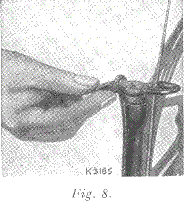
This device simplifies throwing off and replacing the belt. To throw off the belt, move the belt shifter to the left (see Fig 8), working the treadle at the same time. To replace the belt, work the treadle slowly with the band wheel turning toward you, when a revolution or two of the wheel will bring the belt back into its place.
NEEDLES AND THREAD
This machine uses a 15 x 1 Needle - available in sizes 9, 11 ,14 ,16 ,18 ,19 , and 21.
TO SET THE NEEDLE
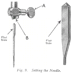
Raise needle bar to its highest position and loosen thumb screw A in needle clamp. Insert needle with its flat side to the left up into the needle clamp B as far as it will go, then tighten thumb screw A.
201K Manual (Part Two)
201K Manual (Part Three)
201K Manual (Part Four)
Part 2
THE NEEDLEBAR Archive at ISMACS International
Online Manuals Section
Singer 201k Instruction Manual (post-1954)
Part Two
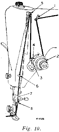
UPPER THREADING
See Fig 10.
Raise take-up lever 5 to its highest point.
Place spool of thread on spool pin.
Lead thread into thread guide 1.
Down and from right to left between tension discs 2.
Into the loop of the take-up spring 3 and to the right until it enters the fork 4.
Up and from right to left through hole in take-up lever 5.
Down through guide 6 on face plate.
Down through guide 7 into guide 8.
From right to left through the eye of the needle.
Draw about two inches of thread through the eye of the needle with which to begin sewing.
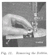
TO REMOVE BOBBIN
Raise the needle to its highest point.
Draw to the left the slide (C) in the bed of the machine and remove the bobbin with the thumb and forefinger of the left hand, as shown in Fig 11.
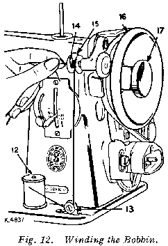
TO WIND BOBBIN See Fig 12
1. Place bobbin on spindle with pin of spindle entering hole in right side of bobbin.
2. Lock bobbin in place by pressing bobbin winder down until latch 15, Fig 12 engages.
3. Place spool of thread on spool pin 12. Draw thread under and between tension discs 13. Lead thread up through hole in bobbin 14 from the inside.
4. Hold hand wheel 16 and loosen knurled screw 17 by turning it over toward you.
5. Hold end of thread and operate machine as for sewing. Continue to hold end of thread until it breaks off.
Allow tension discs to control flow of thread. Do not guide or hold thread when winding bobbin.
The bobbin winder will stop automatically when the bobbin is filled.
Remove bobbin from spindle and tighten knurled screw 17.
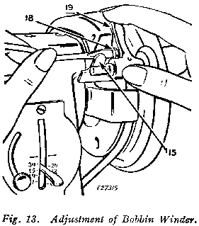
If pressure of bobbin winder pulley against hub of hand wheel is insufficient for winding the bobbin, press down bobbin winder until latch 15, Fig 13 drops and holds it in position.
Loosen adjusting screw 18, Fig 13. With forefinger, push back upper end of slotted plate 19 as far as it will go, as shown in Fig 13, and at the same time, press bobbin winder pulley against the hub of hand wheel.
Tighten adjusting screw 18.
If thread does not wind evenly on bobbin, loosen screw which holds tension bracket 13, Fig 12 in position. Move bracket to the left if bobbin winds high on right; move bracket to the right if bobbin winds high on left.
When bracket is properly centred, thread will wind evenly across bobbin.
Bobbins can be wound while machine is sewing. Follow numbered instructions above omitting item 4.
TO REPLACE BOBBIN
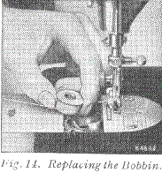
Hold the bobbin between the thumb and forefinger of the left hand, the thread drawing from right to left, as shown in Fig 14.
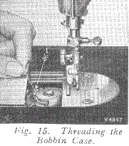
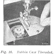
Place the bobbin into the bobbin case and draw the thread into the slot 1, Fig 15 in the bobbin case, as shown. Draw the thread backward between the bobbin case and the tension spring until it reaches the notch 2, Fig 16, then pull the thread toward the right, as shown in Fig 16.
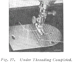
Close the slide, as shown in Fig 17.
TO PREPARE FOR SEWING
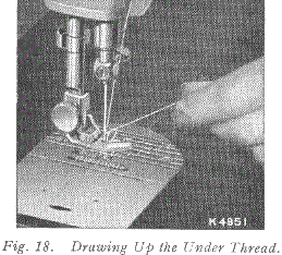
Have the thread take-up lever at its highest position, then, with the left hand, hold the end of the needle thread, leaving it slack drom the hand to the needle. Turn the hand wheel over toward you until the needle moves down and up again to its highest position, thus catching the bobbin thread. Draw up the needle thread and the bobbin thread will come up with it through the hole in the throat plate as shown in Fig 18.
Lay both threads back under the presser foot diagonally across the feed, to the right or left, depending upon which side of the needle the material is to be located so that when the presser foot is lowered, the threads will be firmly held between the feed and the presser foot.
201K Manual (Part One)
201K Manual (Part Three)
201K Manual (Part Four)
Part 3
THE NEEDLEBAR Archive at ISMACS International
Online Manuals Section
Singer 201k Instruction Manual (post-1954)
Part Three
TO START SEWING
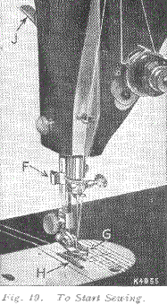
See Fig 19
Be sure to have thread take-up lever 5, Fig 10 in its highest position.
The throat plate has guide lines for seam width gauged from centre of needle hole, and cross lines for gauging square corners.
Place material beneath the presser foot G, turn the hand wheel to bring the point of the needle into the material, then lower the presser foot by means of presser bar lifter J, and start to sew.
Some materials, such as soft finished sheers, nylons, jerseys, tricots and other elastic and spongy textiles, require a slight amount of assistance in feeding during sewing operations.
However, too much pull will stretch the seam, create irregular stitching and bend the needle. Most materials require only guiding for best sewing results.
TO TURN A CORNER
Stop the machine when the needle eye, making its upward stroke, is still in the fabric. Raise the presser foot and turn the work as desired, using the needle as a pivot, then lowere the presser foot.
BASTING
The longest stitch, No. 6 on the stitch indicator, is satisfactory for basting and is easily removed by clipping every sixth stitch and withdrawing the long continuous thread.
Machine basting is firmer and more even than that done by hand in addition to being much quicker.
TO SEW BIAS SEAMS
Use a short stitch ans as light a tension as possible on the needle thread so that the thread is loose enough in the seam to allow the goods to stretch if necessary.
TO REMOVE THE WORK
Stop the machine with the thread take-up lever 5, Fig 10 at its highest point. Raise the presser foot by means of presser bar lifter J, Fig 19, draw the fabric back and to the left and sever the threads on the thread cutter F, Fig 19. Place ends of threads under presser foot.
TO REGULATE LENGTH OF STITCH AND DIRECTION OF FEED. See Fig 20
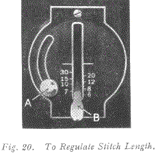
The machine can be adjusted to make from 6 to 30 stitches to the inch, as indicated by the numerals on the stitch indicator plate.
Loosen screw A and lower it to the bottom of the slot, then move lever B until its top edge is level with the figure denoting the number of stitches desired per inch.
Raise screw A as far as possible and tighten it. Thus set, the machine will make the indicated number of stitches in a forward direction.
If it is desired to reverse the direction of the stitching, raise lever B as far as possible, and the machine will make the same number of stitches in a backward direction.
TO REGULATE PRESSURE ON MATERIAL
For ordinary sewing, the pressure of the presser foot on the material seldom requires changing. Heavy materilas require more pressure than lightweight materials. The pressure should be only heavy enough to prevent the material from rising with the needle and to enable the feed to move the work along evenly.
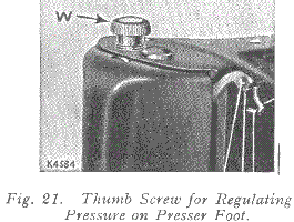
To increase the pressure, turn the thumb screw W, Fig 21 clockwise or downward. To lighten the pressure, turn the thumb screw upward.
THREAD TENSIONS
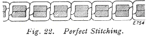
For perfect stitching, the tension on the needle and bobbin threads must be heavy enough to pull the threads to the centre of the thickness of the material and make a firm stitch, as shown in Fig 22.
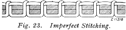
If the needle thread lies straight along the top side of the material, the tension on the needle thread is too heavy, or the tension on the bobbin thread is too light, as shown in Fig 23.
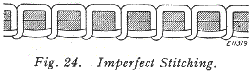
If the bobbin thread lies straight along the underside of the material, the tension on the needle thread is too light or the tension on the bobbin thread is too heavy, as shown in Fig 24.
TO REGULATE NEEDLE THREAD TENSION (See Fig 25)
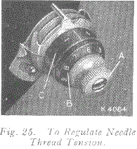
The tension on the needle thread can be tested only when the presser foot is down.
The numerals "0" to "9" on dial B, indicate the different degrees of tension that can be obtained.
When the tension has been correctly set note the number at the indicator line C, so that this setting may be regained should the tension be altered for special work.
To increase tension, turn the thumb nut A gradually to the right (clockwise) until the required tension is obtained.
Each higher number denotes increased tension.
To decrease tension, turn the thumb nut A gradually to the left (counterclockwise) until the required tension is obtained. Each lower number denotes less tension.
the tension indicator C is marked with the signs + and -, which indicate the direction in which to turn the thumb nut A for more or less tension.
TO REGULATE BOBBIN THREAD TENSION
The tension on the bobbin thread is regulated by screw F, Fig 32, which is nearest the centre of the tension spring on the outside of the bobbin case. To increase the tension, turn screw F over to the right. To decrease the tension, turn this screw to the left.
When the tension on the bobbin thread has been once properly adjusted, it is seldom necessary to change it, as a correct stitch can usually be obtained by varying the tension on the needle thread.
DARNING (See Fig 26)
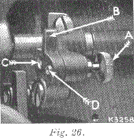
Raise needle to its highest point, turn machine back on its hinges, unscrew knurled screw A as afr as it will go, and move crank B down so that the screw A will enter the upper hole C.
The screw should then be securely tightened. The feed is now inactive and will not impede free movement of the work. Restore machine to its working position and raise the presser bar. Remove the presser foot and fit Spring Darning Foot No. 121094 but do not tighten the thumb screw.
Stretch tightly the article to be repaired in an embroidery hoop and place below the needle by tilting the edge of the hoop. Then lower the presser bar by means of its lifter, and adjust the height of the darning foot to allow just sufficient space for the free movement of the work in hand.
After adjustment, tighten the the thumb screw securely. Now move the hoop backward and forward by the hands until the hole or damaged part is completely covered with stitching in one direction. Then turn the work and stitch across to complete the darn.
After darning, reinsert and firmly tighten the screw A in the lower hole, and replace the presser foot for ordinary sewing.
EMBROIDERY
For surface embroidery, remove the presser foot to give a clear view of the stitching. For lace embroidery, i.e. open work, remove the ordinary presser foot and fit Spring Foot No. 121094. For embroidery the feed should be lowered and the work handled as advised in the preceding paragraph.
201K Manual (Part One)
201K Manual (Part Two)
201K Manual (Part Four)
Part 4
THE NEEDLEBAR Archive at ISMACS International
Online Manuals Section
Singer 201k Instruction Manual (post-1954)
Part Four
TO OIL MACHINE AND STAND
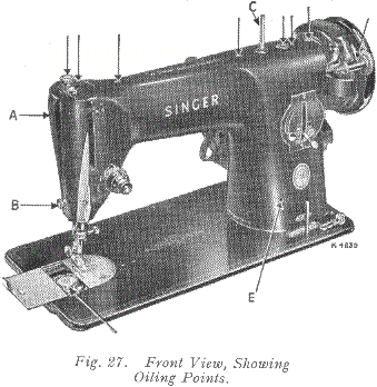
The Arm Spool Pin C is screwed for insertion in the left plugged hole and it is also provided with a screw driver slot. If the machine is used continuously, it should be oiled daily. If moderately used, an occasional oiling is sufficient.
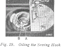
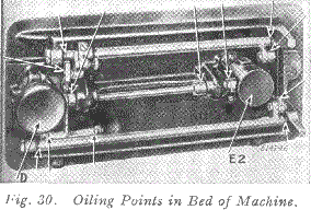
Apply one drop of oil to each of the places indicated in Figs 27, 28, 29, 30 and 31 and carefully clean the machine to insure smooth and satisfactory performance. Oil holes are provided in the machine for bearings which cannot be directly reached.
Remove face plate A, Fig 27, by taking out screw B and slipping plate over screw D, Fig 28. After oiling replace face plate. Draw to the left the slide in the bed of the machine, as shown in Fig 27, while the thread take-up lever (5, Fig 10) is at its highest position, and, after removing the lint and dust which may have accumulated, apply one drop of oil to the sewing hook race in the bobbin case, as indicated by arrow "A" in Fig 29, and a few drops to the oil hole "B" in Fig 29. Then close the slide.
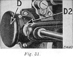
To oil the parts underneath the bed of the machine, turn the machine back on its hinges and apply oil to the oil holes and bearings indicated in Fig 30. 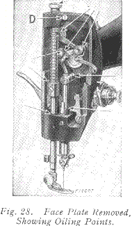 The gears concealed by the gear cover (E2, Fig 30) are oiled through the oil hole (E, Fig 27). The gears concealed by gear cover (D, Fig 30) are oiled through the space just above the cover, as indicated by arrow (D2, Fig 31).
After oiling at D2, rotate the hand wheel toward you to distribute the oil on these gears. To oil the stand, apply a drop of oil to the centres upon which the treadle works, and to the lower end of the pitman rod. Run the machine rapidly for a few minutes so that the oil may reach the bearings.
Neglect to oil the machine will shorten its life and cause you trouble and annoyance. Always use SINGER oil. Inferior oil cogs the bearings, prevents efficient working, and causes rapid wear of the mechanism.
TO CLEAN STITCH FORMING MECHANISM
After considerable use, the stitch forming mechanism may become clogged with lint and this may interfere with the perfect operation of the machine. Occasionally remove the bobbin case according to the following instructions, and remove any lint, etc., which has accumulated.
TO REMOVE BOBBIN CASE (See Fig 32)
The bobbin case may be easily removed without taking off the throat plate, although for the purpose of illustration the throat plate and feed dog are shown broken away.
Remove bobbin from the bobbin case. Turn hand wheel over toward you until the end of hook ring E is toward the front of the machine, as shown. Insert the blade of the small screwdriver into slot C between the ring and the edge of spring, as shown.
With a downward pressure, give the screwdriver one half turn to the right so that it will drop into the slot and unlock the spring.
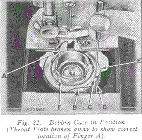
With the right hand hold the hand wheel to prevent its turning and , with the left, place the screwdriver against the edge of the slot in the ring and push it around in the direction opposite to the hook rotation until the circular cut-out B is opposite the spring D. The ring and bobbin case may then be lifted out.
TO REPLACE BOBBIN CASE (See Fig 32)
When replacing the parts, first place the bobbin case into position with the finger A in the opening in the plate under the feed dog, as shown. Turn the bobbin case back and forth slightly to make sure that it is properly seated, then place the hook ring E in position with the cut-out B opposite the spring D. Press the ring into place and turn it in the direction of hook rotation until the spring locks it in position. Then replace the bobbin.
201K Manual (Part One)
201K Manual (Part Two)
201K Manual (Part Three)