All 3 available source parts are included below.
Part 1
THE NEEDLEBAR Archive at ISMACS International
Online Manuals Section
INSTRUCTIONS
for using the improved

Cylinder Shuttle Sewing Machine
New Model
Part One
Every Sewing Machine sent out from the factory is made of the best material and most carefully adjusted, so that after careful unpacking it can be used at once. But before beginning to sew, it is advisable to read these instructions carefully through first, even if you are experienced with the machine.
All the bright parts of the machine are well greased before it is sent off, so as to prevent rusting. When the machine is unpacked, wipe away the grease and any dirt that may have come into it by using paraffin oil (US = kerosene - AQ), and then re-oil the machine with the best sewing-machine-oil.
All machines leave the works with the hand-wheel disconnected
from the mechanism in order not to disturb the proper threading which is shown
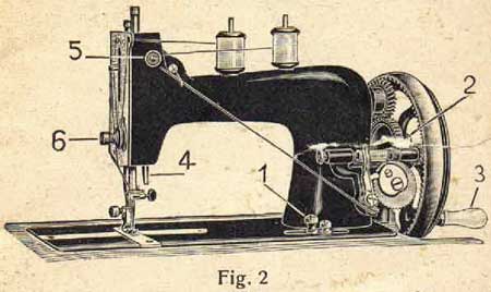
in Fig. 2 and 5.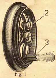
To set the handmachine in motion, turn the china handle 3 Fig. 1 in its joint, till it snaps in. Then turn the little knob 2 Fig. 1 on the spoke of the hand-wheel round so far as to fit the little pin into the slot. After this the hand-wheel has to be turned till the lengthened end of the knob enters the hole provided for in the large cog-wheel. Thus, the machine is ready for sewing.
To disconnect the movement of the machine, draw back the little knob 2 Fig. 1 on the spoke and turn it somewhat. Then pull out the china handle and turn it as practice to guide the work by placing a piece of material underneath the presser-foot without having the machine threaded. Let down the presser-foot by the lever 4 Fig. 2 and then turn the hand-wheel slowly always in the direction shown by arrow in Fig. 3 i.e. away from you. You may fix a piece of paper on the material with straight and curved pencil lines drawn on same and guide the material over these lines under the needle by operating the machine.
Sewing over thick seams should be done slowly and when sewing square corners leave the needle in the material at the end of the seam, lift the presser-bar a little and turn the material in the desired direction.
Large and Small Stitches
The length of the stitches can be practised at the same time. The stitch regulating thumb-screw 1 Fig. 2 is found just below the winder. If this screw is loosened and pushed towards the right, the stitch becomes larger and if it is pushed towards the left, the stitch becomes smaller. When the desired length of stitch is obtained this screw should be tightened again, so as to prevent its moving.
For filling the bobbins with cotton the
Bobbin-winder
is used. The machine is supplied with the ratchet bobbin-winder Fig. 2 and Fig. 3, which releases itself automatically when the bobbin is full. The ratchet bobbin-winder is very easy to work, not exposed to any interruptions and gives a tight and clean convoluted bobbin.
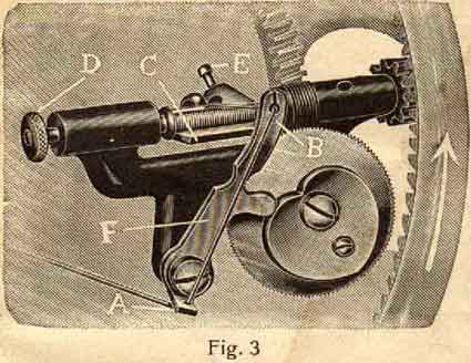
The thread is passed through the tension disks 5 Fig. 2, then first through the eye A of the thread-guide F Fig. 3 and secondly through the eye B of same.
When inserting the bobbin press the flap C of Fig. 3 down, pull back the piston D and insert first one end of the bobbin, then the other so that the small pin on the right side passes into the hole of the bobbin. The end of the thread is passed through this little hole from left to right and jammed between this end of the bobbin and the winder. Take care that the thread-guide F Fig. 3 is in position to the right hand in order to obtain a full and smoothly filled bobbin. By lightly pressing the winder to the front it is set i motion. It will be found that the winder releases itself as soon as the bobbin is full.
 Should
the bobbin get too full, turn the little regulating screw E
of the flap C to the left, or if it does not
get full enough turn the same screw a little to the right.If you do not understand
it properly, ask for the advice of an expert, so that the apparatus is not
spoilt through ignorance.
Should
the bobbin get too full, turn the little regulating screw E
of the flap C to the left, or if it does not
get full enough turn the same screw a little to the right.If you do not understand
it properly, ask for the advice of an expert, so that the apparatus is not
spoilt through ignorance.
The Fixing of the Bobbin-winder
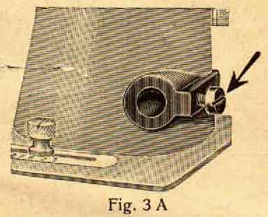
The whole bobbin-winder is attached to the arm of the machine by a round pin which is fastened by means of a small screw Fig. 3 A and by loosening same the whole winder can be taken off.
To place the apparatus in its right position again, the following is to be noticed. When putting a full bobbin into the winder, the flap C Fig 3 should be tight on the bobbin and the winder is to be pushed in until the little brass cog-wheel engages the cog of the hand-wheel and then tighten the fastening screw Fig. 3 A.
This is especially to be considered when it is necessary to take off the bobbin-winder for repairing purposes.
The Needle
Flat-shanked needles are to be used only.

The needle has on one side a long groove and on the other a short one and must be fixed so that the long groove is towards you.
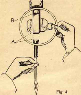
The needle-bar being at its highest and the wing-screw of the needle-clamp loosened, push the needle from below, the long groove to the front, as high as it will go into the needle clamp. When the needle stops at point B Fig. 4 above the needle-clamp, it is in position, and the wing-screw can be tightened again. Be sure that the plane A of the needle lies on the plane B of the needle-bar. The needle-eye must point to the front.
Perfect work can only be produced if the needle is in proper position passing
through the middle of the hole in the throat-plate and neither blunt nor bent,
as this would cause defective stitches. The size of the needle must be chosen
in proportion to the thickness of the thread and the table on page 11 will
be a guide for selecting the needle-size for the thread you are using. Wrong
needles cause missing of stitches and make bad seams.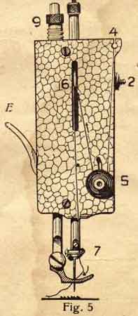
The Threading of the Upper Thread
is very easy. As each machine is sent out properly threaded, one should, after unpacking the machine, look at the thread as shown in Fig. 2 and 5.
It runs from the reel which is on the reel-pin through the eyelet 4 of the front-plate, then downwards between the tension-disks 5, form there on to the thread-lever 6 and then down again through the eyelet 7 to the needle. It should be passed through the eye of the needle from the front and pulled through for about 2 inches.
When threading the machine the presser-foot-lifter E should be raised so as to release the tension and allow the cotton to be easily passed between the tension-disks. It is only after the presser-foot-lifter is let down that the tension can be regulated.
The Threading of the Cylinder Shuttle
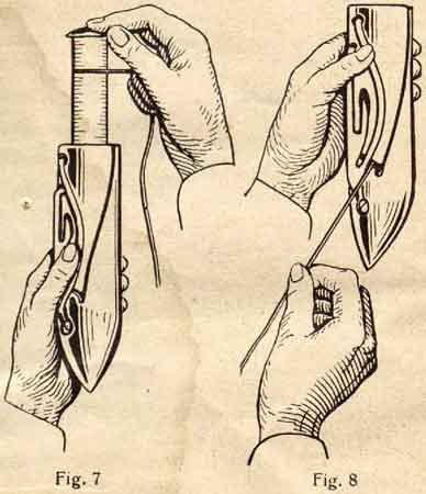
is most simple, in fact the shuttle, as it will be seen in the following illustrations, is almost self-threading. Hold the shuttle in your left hand, drop the bobbin with your right hand into the shuttle, but in such a manner that the thread comes off the bobbin from the upper side and form left to right (i.e. the bobbin-disk with hole on the top Fig 7).
When the bobbin is pushed into the shuttle, the thread is pulled downwards between the slit of the shuttle by putting
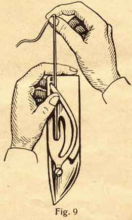
the right hand downwards a little to the left like Fig. 8 shows. Then the thread is pulled round the slit upwards, whereby it slides by itself into the spring. With a sudden jerk it jumps under the thread-holder of the spring (Fig 9) and is under the tongue of the tension-spring.
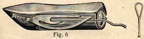
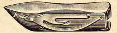
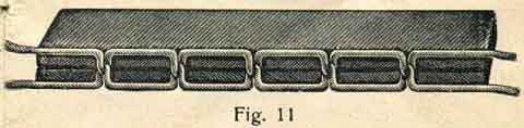
It is advisable when threading the shuttle to press the forefinger of the left hand slightly on the top of the inserted bobbin, so as to prevent the bobbin from falling out. The tension of the shuttle-spring is regulated by the small screw A Fig 6 in the shuttle. The tension is right when the thread can be pulled out with a little resistance (Fig 11)
When placing the shuttle into the machine, the thread should be pulled out about 2 inches, so that it can be taken up by the upper thread. Care should be taken that no bits of cotton or dust collect in the shuttle or under the shuttle-spring, otherwise the bobbin will turn irregularly, the thread might break and the machine be put out of order.
The Shuttle
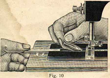
is put into the machine in the following way. Turn the wheel until the needle-bar is at its lowest point, pull out the left slide of the shuttle-race Fig 10 as far as it will go and place the shuttle with the point towards the right and the flat side to the front. This should be done very carefully, not by force, so as not to damage the carrier. The hand-wheel should not be turned until the shuttle is properly put in and the slide closed. In order to remove the shuttle, one should simply bring the needle-bar to its lowest point and pull out the slide, which is provided with a shuttle-ejector. The shuttle-ejector lifts the shuttle up itself, so that you can easily catch hold of it with 2 fingers (Fig 10)
Screw-driver, scissors or other instruments must not be used for taking out the shuttle, as by doing this the tension-spring gets bent and the machine will not work properly.
Before beginning to sew
one should get up the lower thread. This is done by holding the upper thread slightly with the left hand, turning the hand-wheel towards you with the right hand until the needle has passed through the needle-plate and has come up again to its highest point, by which the lower thread has been brought up through the hole of the needle plate, so that it can easily be pulled out. Then the two threads should be laid under the sewing-foot towards the back.
Now the sewing can begin. Place the material under the sewing-foot, bring this down by pressing the foot-lever E Fig 5 and begin to sew.
Sewing over thick seams should be done slowly, as otherwise the needle might easily be bent or broken.
When wishing to remove the material, turn the hand-wheel of the machine so that the thread lever 6 Fig 5 stands at its highest, lift the foot-lever E Fig 5 and pull the material slowly towards the back. The threads should be cut so that the ends are still 2 inches long.Never pull the material towards you as this might bend the needle, which afterwards might easily damage the needle-plate and this is often the cause of irregular stitches, broken cotton and needles.
The Thread-tension
As faultless work can only be produced through a proper tension it is advisable to give special attention to the regulation of same. When starting a seam, be sure that the tension of the upper thread (Fig 5) as well as of the shuttle (Fig 9) is equal.
If both, the upper and the lower thread have equal tension and cros each other in the middle of the material so that the stitches appear on both sides of the material as equal as possible, as is shown in the cross-section, the tension is right and you may begin to work.
Vesta Manual - Part Two
Vesta Manual - Part Three
Part 2
THE NEEDLEBAR Archive at ISMACS International
Online Manuals Section
INSTRUCTIONS
for using the improved
Cylinder Shuttle Sewing Machine
New Model
Part Two
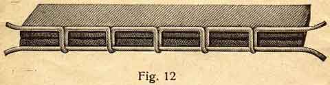
If small knots or loops (Fig 12) are seen underneath the material, the upper tension is too slack, as the upper thread is drawn through by the lower thread. In this case tighten the nut 5 Fig 5 on the front-plate of the machine (which produces the tension of the two disks) until these knots underneath disappear. At the same time you must make sure that the thread-tension in the shuttle is not too tight.
The tension of the shuttle-spring (like in Fig 6 screw A) must be regulated properly first.
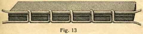
If the regulation-nut of the tension-disk 5 (Fig 5) has been tightened too much, the knots and loops appear on top of the material, Fig 13, because the upper tension is too tight and the regulation-nut must be loosened a little or hte tension of the shuttle is not strong enough.
The Presser-foot Bar
is available to press down the feeder on to the material. Thin and flimsy material requires but slight pressure whilst thick and tightly woven material requires stronger pressure. The pressure, which is obtained from a spring in the head of the machine, may be regulated by turning the nut 9 Fig 5 on the top of the machine behind the needle-bar clockwise if required stronger, or anti-clockwise if less pressure is required.
The presser-foot bar is properly regulated by the factory for shirting and similar material.
To obtain a regular and straight seam it is absolutely necessary to use perfect needles which must be neither blunt nor bent, and must be in proportion to the cotton as shown by the following table:
Needle Sizes
|
German
|
English
|
American
|
*Cloth* |
Cotton Thread No. |
Silk No.
|
Linen Thread No. |
|
6 7 |
00 0 |
8 9 |
embroidery work finest cotton cloth, linen, cambric etc. |
200 150 100 |
000 -- 00 |
--
|
|
8
|
B C |
11 13 |
very fine linen, calico, shirting, finest silks etc. |
100 -- 80 |
00 0 |
--
|
|
9
|
1/2
|
14
|
shirting, calico, cotton cloth, silk, all kinds of general work |
80 -- 60 |
0 A |
--
|
|
10
|
1 1 1/2 |
16 17 |
all kinds of heavy calico, thin woollen material, heavy silk etc. |
60 -- 40 |
B C |
90 -- 80 |
|
11 12 |
2 3 |
18 19 |
woollen material, children-suits and ladies coats etc. |
40 -- 30 |
D
|
70 -- 40 |
--
The Oiling and Cleaning of the Machine
Owing to the perfect supervision in the factory, only light running machines are sent out. Should at any time a machine run heavy it can only be due to its not being properly oiled.
The more a machine is used the more often it must be oiled, if necessary several times a day. Only pure machine-oil free from acid and resin should be used, which can always be purchased. Bad oil will easily spoil the machine.
If the oil has become thick after a certain time owing to the machine having been idle for a long while, a few drops of paraffin oil (US = kerosene. AQ) should be put into each oil-hole and the machine worked quickly for a minute or two, during which the paraffin oil (kerosene) removes all the thick oil. Then wipe off all the overflowing paraffin oil and put a drop of pure machine-oil into all the oil holes. The latter are marked in red. Always use specially prepared sewing machine mineral oil, on no account use any vegetable oil. In fact oiling is required werever there is friction, especially in those places which are marked with 0 (Fig 14).
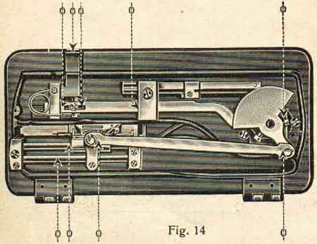
The needle-bar should be oiled at the upper as well as the lower end, but also very little and carefully, so as not to soil the material. Oil-holes are provided for all the parts that cannot be reached directly by the oil-can, and they are made conspicuous by being painted red.
The nickel-plated cover on the back of the arm can be opened when the inside parts want oiling.
*****************
The Various Attachments
After being quite familiar with the plain sewing and with the working of the machine generally, one can begin to learn to use the various attachments as described on the following pages.
The Common Foot (No. 1401)
is fastened to the machine. It serves chiefly for all ordinary plain sewing.
The Adjustable Hemmer (N0. 1410)
Fig. 15
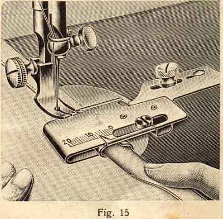
This hemmer is fastened to the bed plate by means of the thumb-screw 1411. The material is folded for about 2 inches and pressed into the hemmer from the side until it folds itself to the desired width, then pushed under the needle and the presser-foot lowered on top of it, after which the sewing may be started. Care must be taken that the material enters the hemmer freeley. The adjusting of the hemmer is done by means of the small screw in the slit.
The Guide (N0.1412)
Fig. 16
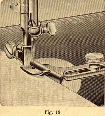
is also fastened to the bed-plate with the thumb-screw and is used in connection with the edge sewing foot No. 1407 for making a seam parallel to the edge of the material and may be adjusted to the required width.
The Quilting Guide (No. 1408)
Fig. 17
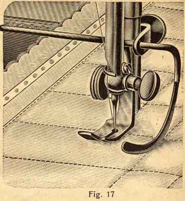
is used for stitching all sorts of quilted material in regular rows and squares without it being bacassary to mark first the lines. It is fastened at the presser-bar by means of the thumb-screw clamp No. 1409. First make a straight seam, them move the material towards the right as far as the seams are to be apart and set the quilting guide to this width, so that its lower end passes along the various seams. In this way the various seams will all be at an equal distance from one another.
The Narrow Hemmer (No. 1402)
Fig. 18
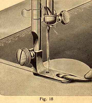
Fasten it in the place of the common foot. Begin by folding the material for about 2 inches and pass this folded end into the hemmer up to the needle, lower the presser-bar and start sewing slowly. Care must be taken that the material passes very evenly into the hemmer. If the material is very soft and difficult to get into the hemmer, one should fasten a thread to the end and pull it through the hemmer as described above. The illustration shows how the material has to be held, so as to pass properly into the hemmer.
The Broad Hemmer (No. 1403)
is used in exactly the same way as the narrow hemmer.
The Seam Feller (No. 1404)
Fig. 19
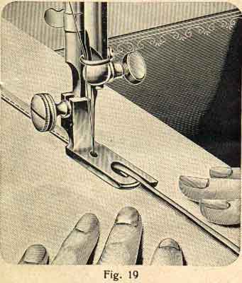
is fastened exactly like the hemmer. In order to fell a seam, put the 2 pieces of material on top of each other, so that the lower one projects about 1/4 of an inch. The projecting edge is passed through the feller in a similar way as with the hemmer and is sewn on the upper material. After flattening out these two pieces of material thus sewn together, there remains a high seam as shown in the illustration, which must then be sewn down flat.
**********************
Vesta Manual - Part One
Vesta Manual - Part Three
Part 3
THE NEEDLEBAR Archive at ISMACS International
Online Manuals Section
INSTRUCTIONS
for using the improved
Cylinder Shuttle Sewing Machine
New Model
Part Three
Instructions for keeping the Machine in proper Order
If the machine works badly, drops stitches or if the cotton breaks, one should examine:
Whether the needle is in its right place and whether it is blunt or bent.
Whether the needle is of the right thickness in proportion to the cotton.
Whether the cotton is even, and is properly threaded.
Whether the tension is right, not too tight and whether the needle-palte is damaged by the needle, as otherwise the cotton is easily broken when passing the rough edges of the needle-plate.
If in spite of the observance of the above instructions the machine will not work properly, you should apply to the shop where the machine was purchased, but under no circumstances get strangers to interfere with it, as they often spoil the machine either wilfully or from ignorance.
The
Cylinder-Shuttle Hand-Machine with simple Hand-wheel
is supplied with the following attachments:
(1401) 1 Common Foot, attached to the machine
(1407) 1 Edge Sewing Foot
(1408 & 1409) 1 Quilting Guide with Screw-clamp
(1410) 1 Adjustable Hemmer
(1411) 1 Thumb-screw for securing attachments
(1412) 1 Guide
(1413) 1 Large Screw-driver
(1414) 1 Shuttle Screw-driver
(1415) 1 Oil-can
(705) 6 Needles, 1 of which in the Machine
(1747) 4 Bobbins, 2 of which in the Machine
(1786) 1 Thread-lever Spring
1 Instruction Book
******************
Sewing Machines with multiplying geared Hand-attachment
are exactly the same as those described in this instruction book, only they have a
double hand-wheel.
When the machine is to be used, turn the lever of the hand-appliance into its place and connect the crank with the hand-wheel, which will set the machine in motion. The hand-appliance should always be carefully oiled.
To disconnect the machine hold the wheel with your left hand, turn the disconnecting disc "a", as shown in the illustration, towards you with your right hand.
To reconnect the machine turn this disc in the opposite direction. The hand-wheel should always turn towards you.
The ratchet bobbin-winder is put in motion by a rubber-ring.
Besides the parts mentioned on page 17 the following extra parts will be attached to this machine:
(1402) 1 Narrow Hemmer
(1403) Broad Hemmer
(1404) 1 Seam-feller
which are already described exactly on page 15 - 17, furthermore (1705 1 Throat-plate
and (705) 5 Needles
******************************
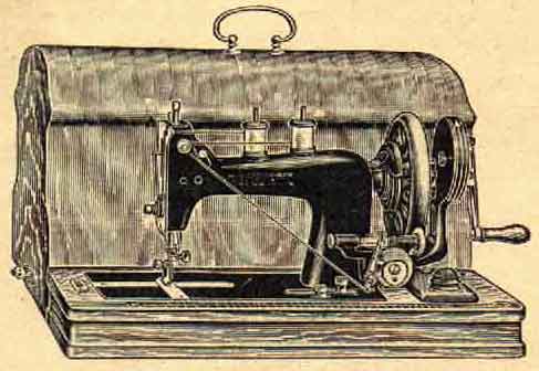
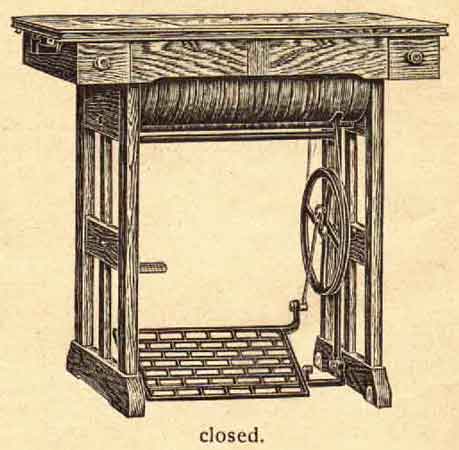
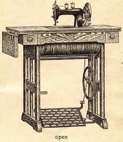
Model JUNIOR
Drophead Cabinet Machine with wooden Sides fitted with Cylinder Shuttle
********************
Vesta Manual - Part One
Vesta Manual - Part Two