Film cameras
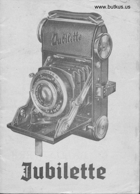
Balda Jubilette User manual
User manual for Balda Jubilette. 13 pages in English. Read the original PDF, download or print a copy without registration.
13 pagesEnglish2.5 MB PDF

Loading your manual…Open PDF directly
Document details
- Brand
- Balda
- Model / document
- Balda Jubilette
- Document type
- User manual
- Language
- English
- Pages
- 13
- File size
- 2.5 MB
- Category
- Film cameras
- Document date
- Not specified in catalog
Search available document text
Find a term, then jump to its page in the original PDF. Image-only pages may not be searchable; check the PDF for exact wording and diagrams.
Page 4 · Read text
Fig. 1                                                     Fig. 2


   A  Latci  for camera bacft
   B  Automatic counter
   C  Press-button to open the camera
   D  Tubular viewfinder
   E  Struts
    F  K"y  for winding  bacl<the film
   G  External sh utter release
   H  Baseboard l"g support                             O  Counter clutcl button
        ]  Index for  iris diaphragm                                P  Lower film supply dramber
   K  Frontlens for focusrng                                        0  Spring pressure plate
    L  Rotating collar for setting exposure time                  R  Frlm pressure spring
   M  Lever for setting shutter                                S  Upper take-up spool (not rem'Jvable)
   N  Film winding k.y knob                                    T  Film transport gear
4
View original page 4Page 6 · Read text
Film-Transport
  Now  depress the clutch button (Fig. ? Ol
which is loCateddirectly under the windi.g
knob (Fig-the2 N), releasethe clutch and wind
on until     winding knob  is again auto-
matically stopped. In order to be able to
depress the counter clutch  it  is necessaty
to  slide the sa{ety spring-and-Fig. 5 forward,
toward the winding knob       to  hold   it
{orward until the clutch botton is depressed.

                                                       Fig. 6

                                                  button and advancing of the winding knob
                                                              until automaticallY stoPPed.
                                              As an indication thif the film is properly
                                                   winditg up on the. take-up .tP99!' observe
                                                        that th; t"*ind key (Fig.1 and 2 F) is actually
                                                        revolvir,g along with  the  *i.nding  knob.
                                            The  c"tti"t"  ts now ready for the first expo-
                                                     sure,but do not overlook setting -th. counter
                                                          to number "1". To do this proceedas foilows:
 Fig. 5
                                            Setting the counter (Fig. 6)
 This can easily be done hy  sbifting the           The countirg mechanism is located opPo-
 sa{etyspring-samEwith the thumb and depressing,          site  the  windi-ng knob.   It  consists of  a at the        time, the  clutch button  with         round  plate  wit[  a cut-out sector having
 the index finger. R.peat twice this manipu-        an ind.i, rnd makirg the underlying number
 lation, namely-,short depressionof the clutch          plate visible.
                                                                                                                                      I 8
View original page 6Page 7 · Read text
Fig. 7

   By turning the winding knob, the coun-
ting disc advancesautomaticallyto the next
lilm number mark.
   Press on the milled axis (Fig. 6) of the
counterdisc,and turn the disc in the direction
of the arrow until the triangular index stands
on the FIRST MARK FOLLOWING   "O".

                                                                     Fig. 8

n                                                                  TI
                          www.butkus.us
View original page 7Page 9 · Read text
Finder
   The new tubular direct view finder (Fig. I
    2 p)  consists of trvo lenses in a teleico-pic
"tldtube. Place the  finder  sight  (Fig. 9)  close
to the eye.
Depth  of focus
   A  depth  of Focus table  is mounted  on
the back of the camera (Fig. l0).
External  shutter  release
   This camera is fitted with external shutter
rele.rse;the shutter being operated by simply
presjjng the press-button G, as shown by-harids,Fig. i.
   The camera is held  tight  in both
with.on"  finger actuatinf  th-e shutter, thus
ensuring a smooth and steady release.


                                                                        Fig. 10


T4                                                             15
                           www.butkus.us
View original page 9Page 10 · Read text
OPERATING THE SHUTTER        Please observel
                                             When  setting  the  shutter  {or instantane-
Snapshots   (Instantaneousexposures)                                                   ous exposures of  t/r oo sec. or  shorter  time,
   The rotating coll ar L (Fig. 1) on the shutter          a strong  resistance is offered by the shutter
is turned to bring the desired exposure time            spring. To  avoid  that damage be done  to
opposite the triangular exposure time index.           the mechanism  of the  shutter  or  its  carrier,
Then  adjust the diaphragm to  the desired          a counter-pressure should be applied  while
aperture by moving the index / (Fig. I ) until            the shutter  is being  set.
it  is opposite the correct stop number. The
selection of the lens aperture may be based
upon experience but the use of exposure
meters is recommended.
   The Compur  shutter is set by moving
the lever M  (Fig. 1) toward the top of the
shutter case,until   it catches and remains in
that position. The preliminary setting is done
only  for "snapshots" ( -. instantaneous €X-
posures)of one second or shorter time. The
setting lever is not used for either a "Bulb"
or a "Time" exposure, as in those casesthe
shutter operates directly.
   The shutter  is released by the externatr
shutter releaseG in Fig. 1. The motion should
be gentle and gradual. Avoid  jerking the
camera when making the exposure. A cable
releasemay be employed  if desired, and its
use is recommended.


                                                                     Fig. 11
I6                                                      17
View original page 10Page 11 · Read text
Time exposures.                         Closing the camera.
                                                        Press down upon the two struts as shown
   For  any  exposures  of  greater  duration               in Fig. 1 1. The mechanism  is thus released,
than       '1,,r,second it is essential that the camera          and the lens support, together with  lens and
be {irmly supported in a motionless position.             shutter, as well  as the button  of the  exter-
By using thre baseboard 1.g suppo rt H,  the            nal  shutter  release withdraw  automatically'
camera may  be  prope rly  supported  upon              into  the camera bodv .
any firm, level sur{ace. It  is preferable, how-             To  protect   the  iamera  against  being
ever to support  the camera upon  a tripod,          damaged,  keep   it  in  a leather  case.
engaging  the  tripod  screw  in  the  tripod
bushing.
   The  shutter  collar L  is rotated  until  the
triangular  index  is opposite the  letter  "8".
This adjusts the shutter for "Bulb"  exposures
when the shutter is opened by pressure upon
the external release button  or cable release
and remains open as long  as the  pressure
is maintained.
   For "Time"  exposures the rotating collar                                             ((T"is set to  bring  the  letter      opposite the
triangular  index.  Pressure upon  external or
cable release opens the shutter which  then
remains open   until  a second  pressure  is
applied  to  the release to cause the shutter
to  close.

   When   the  exposure  has  been  made
turn   the  focussing  mechanism   again  to
the  "infinity"   position.                                                  Fig. 12
                                                             1918
                          www.butkus.us
View original page 11Page 12 · Read text
Rewinding the film.                     Hold the camera steady
   When  the 36th mark  has been reached            To  obtain  needle-sharp  negatives,  it  is
on the number  plate  of the counter, which             of greatest importance  to  hold  the camera
is at  the same time  marked   "0",  try  once            absolutely  steady during  exposure.
more whether  the  film  winding  knob  can                                                           For  this reason the exposure should be asbe  turned   to  the  next  automatic  stoo.  In                                                             short  as possible,  and, correspondingly,   thethis case, one more  exposure  can be made.                                                               largest appropriate diaphragm-stop  should be   When the winding  knob  does not  further                                                      used, to shotten the correlated exposure time.advance, then the film  must be spooled back
into  the supply  chamber  cartridge,  because              Shorter exposures at larger lens apertures
the  upper  film  take-up  spool  can not be              will   yield  negatives  of  more  satisfactory
removed  from  the camera.                          sharpness than exposures where  the  optical
   Withdraw thewinding knob (Fig. 1 and 2N).           advantages of  smaller stops have been ofiset
This makes  it possible to operate the rewind.                                                      by  even  slight movement   of the camera or                                                                                                                           I{*
   Take the camera into  the  le{t hand, and            the object during  exposure. Suc-h movement
with  the  right  hand  turn  the  rewind  key            destroys  the  crispness of  the  outlines.
(Fig. 1 and 2 F)  clockwise,   until   the  iilm                                                    The  relative shortness of the focal lengthhas  all been wound  back into  the cartridge.                                                              of the 2"                                                                lens in                                                                         the                                                                               ensures                                                                                                a                                                                                  III                                                                                Jubilette    During   the  rewinding   of  the  film  the               *t                                                                    sufficient                                                                 depth                                                                                        of                                                                             {ocus                                                                                                         for  most                                                                                                 photo-number  disc of the counter  is also turning                                                          graphic   conditions,   even   at  rather   largebac-k, so  that  the  position  of any exposure                                                         apertures. There  is also a pictorial  gain  incan be located.
                                                                 limiting   critical .sharpness to  the  principal    After  the counter  disc  is returned  to  the
                                                                object,  whici,   of  course was the one  fotu-"0" position, turn rwo or three times further;                                                   sed upon. it will  also be noticed that the rewinder can
now  be  turned  verv  easilv.  This  indicates
that the exoosed film has been returned into
the daylight  cartridge, which can be removed     '
in   full  daylight   (but  should  be  protected
against  direct  sunlight).
20                                                                 2I
View original page 12Page 13 · Read text
Tripod Socket.
   Longer  exposures, generally  more  than
 t/25 second, require  a firm  support   for  the
 camera, preferably  a tripod.  A  tripod  socket
 i s  p r o v i d e d    t o  a t t a c h   t h e  J u b i l e t t e
conveniently   to a tripod.  This  tripod  socket
is on  the same  side  of  the  camera whicl
also  bears  the  winding   knob  and  clutch
button.
    This  places the camera on  the  tripod   in
a horizontal  position,  {or horizontal  pictures.
The camera extends  to  the  right,  allowing
access to  the  {ilm-transport   medranism  on
the underside.
    For  vertical  pictures  (vertical  camera),  it
is necessary to  employ  a swivel-Top   (ball
and  socket) Tripod  head,  whicl   permits  a
ninety  degree dip,  to  bring  the camera  into
the  required  upright  position.  At  the same
time,  the Swivel-top  permits  full  tilting  and
panoraming    in  any  position,  without   the
irksome  readjustment   of  the  tripod   legs.


22
                           www.butkus.usiL
View original page 13Related documents and language editions
From the M. Butkus archive. Original publisher and archive notices are retained.
Check the model and edition against your equipment.
PDF verified 2026-10-10.