Camera accessories
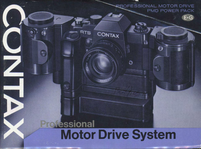
CONTAX Pro Motor Drive Systeminstruction User manual
User manual for CONTAX Pro Motor Drive Systeminstruction. 47 pages in English. Read the original PDF, download or print a copy without registration.
47 pagesEnglish8.6 MB PDF
Loading your manual…Open PDF directly
Document details
- Brand
- Contax
- Model / document
- CONTAX Pro Motor Drive Systeminstruction
- Document type
- User manual
- Language
- English
- Pages
- 47
- File size
- 8.6 MB
- Category
- Camera accessories
- Document date
- Not specified in catalog
Search available document text
Find a term, then jump to its page in the original PDF. Image-only pages may not be searchable; check the PDF for exact wording and diagrams.
Page 2 · Read text
Congratulations on purchasing the most advanced motor
                                                 drive on the market. Your Professional Motor Drive or
                              PMD is a high speed, highly versatile and easy to operate
                                           unit employing the latest electronics techniques and
                                            includes a  built-in electromagnetic shutter release,
                                       making possible extended use with a wide variety of
                                                   accessories. lt features a unique built-in intervalometer
                                       which synchronizes at all shutter speeds including auto
                                                  to offer not only high-speed sequential operation up to b
                                                       fps, but full second interval speeds from 1 sec. to 60 sec.
                                            Moreover, the accessory PMD Power Pack also features a
                                                         built-in electromagnetic  shutter release which is extreme-
                                                ly handy for vertical shot, and also enebles use of theContents:
Professional Motor Drive System .      4          power pack as remote control power source.
Basic Motor Drive Assemblies . . . . . .  6          Other features include an automatic shutoff mechanism,
Description of Parts.                B       LED film-end indicator and a unique power adapterSpecifications              ....12                                     which fits into the camera's battery compartment inUsing the Power Adapter.         . . . 14Mounting the Moter Drive .           . . 16           place of the 6-V camera battery to operate the motor
PMD Power Pack                                    drive and camera jointly from the power pack unit.  Batterylnstallation                               ...18                                                   ln addition, the PMD has the capacity to transport2SO-  Hook Up with the Motor Drive .                                           . . . 22Motor Drive Operation                          expoure bulk film rolls, can be wireless operated with
  lnterval Dial .                 ...24           the Infrared Controller Set, and used with the optional
  Frame Counter                            ?_B       AC control Box for extended interval shooting from  j
  Film LoadinganOWinAinS.  . . . . . . bO            sec. to 24 hour. All the features for heavy duty motor Shooting                                             . . 32                                                drive photography are at your finger tips. Welcome to FilmRewind....                                    36
Use of the Motor Drive wit'h                        the world of PMD photography  .   .
 OtherContaxAccessories  . . . .  . 38
PMD Control Cords 100/300 . . . . . . 42PMDPowerPackJacket   ....44
Other Motor-Drive System
 Accessories            ......46
View original page 2Page 7 · Read text
Professional Motor Drive
@ Frame Counter            o
@ Countdown Dial                   @@ Interval Dial
@ lnterval Lock Release Button      @
@ lro Fitm-End Indicator                   @
@ Release Socket
@ Camera Mount-Screw Handle      @
@ PMD Power Pack/Tripod Socket     @
@ f itm-Rewind Release Lever
@ Power Pack Connector
O crip
@ Shutter Release Button
@ Power Adapter Contact
@ f itm Drive Spool
@ Camera-Mount Screw
@ Camera Coupling Terminal
@ External Power Socket
                   @@ Power Socket Cap
                   @
                   @
                   @
View original page 7Page 8 · Read text
Prof i-Motorantrieb
 C aitozah'lwerk
@ zanwerkskala
@ gitototgezeitskala
@ Entriegelungsknopf der Bildfol-
    gearretierung
@ L E D-F   i I mende-Anzeige
@ Auslosebuchse
@ Drehgriff der Kamera-Befesti-
    gungsschraube
                                           i -Batter iebehdlter/Stat     i vge-@ Prof
   winde
@ Entriegelungshebel fur Filrnrtick-
    spulung
@ AnschluB  fLir Batteriebehdlter
O critt
@ Versch   I uBausl oseknopf
@ Kontakt fiir Fremdstromadapter
@ f itmtransportzapfen
' @ Kamera-Befestigungssch raube
                                                                            I uBk lemme@ Kamera-Ansch
@ AnschluB fur Fremdstrom
@ Abdeckung der Stromversorgungs-
   buchse
View original page 8Page 10 · Read text
Prof   i -Batter iebehii lter
O Batterieprufer
@ Batterieprtif knopf
@ Versch   I uBzusl oseknopf
@ Stativgewinde
@ Drehgriff der Befestigungsschraube
@ Befest igungssch rau be
@ AnschluB fur Motorantrieb
@ Batteriefachdeckel
@ Batteriefach
@ Prof i-Batteriemagaz  in
O Entriegel ungsknopf  frir Batterie-
   fachdeckel
View original page 10
Page 12 · Read text
The accessory power adapter can be used to power the
camera's electrical circuitry directly via the batteries
within the PMD Power Pack. In this instance the came-
ra's 6V silver oxide is not used. In principle,  it isa good
idea to use the power adapter when using the motor
drive, especially in extreme weather conditions, in order
to assure synchronized operation of the camera and
motor drive via one power source.

To Connect:
E Unscrew the camera's battery compartment cover and
remove the 6V battery.
E Screw the power adapter firmly into the battery com-
partment. (Place the battery compartment cover and
camera's battery in a safe place to prevent loss.)
CAUTION: The camera's film advance lever will not
function when the power adapter is used and attempts
to wind the film by hand may result in breakage.
Always advance the film with the motor drive mecha-
nism when using the power adapter, When not using the
power adapter, advance the film by hand ONLY when
the motor drive's interval dial is set to OFF.
View original page 12
Page 13 · Read text
The Professional Motor Drive screw-mounts to the bot-
 tom of the camera. Align the motor drive's camera-
 mount screw with the camera's tripod socket and make
 sure that other contact points (camera coupling terminal,
 film drive spool, etc.) are lined up properly for mount-
  ing. Then, screw the motor drive firmly unto the camera.
 Fold the mount-screw handle in after mounting.


16
View original page 13
Page 14 · Read text
The PMD Power Pack uses twelve 1.5V AA-size penlight
 batteries (high performance alkaline batteries 3r€ l'€colrl=
 mended). Six batteries fit into each of the two battery
 cases, which in turn are inserted into the power pack's
 battery compartment.

 To Load Batteries:
 E Pusfr upwards on the battery cover release button and
 open the battery compartment cover,
                              manganese penlight bat- E Insert six AA-size alkaline or
 teries into each of the battery cases by matching their
 polarity with the (+) (-) engravings on the battery cases;
 or by matching the (-) contact of the battery with the
 spring in the case.
                       cases into the left and right sections B Insert the battery
 of the battery compartment, making sure that the bat-
 tery case terminals line up properly with the contacts
  inside the battery compartment.


18
View original page 14Page 15 · Read text
cover.4 Ctose the battery compartmqntE Press the battery checker button to see if batteries are
functioning properly. lf the needle jumps into the green
section of the checker window,  it indicates that voltage
is adequate (15 - 18V). When the needle no longer rises
into the green section of the battery checker, batteries
require replacing.
.   lf Ni-Cd penlight batteries are used, the checker will
not rise into the green due to the voltage differences
between Ni-Cd and other penlight batteries. This does
not affect performance, however.
Precautions with Batteries
o When changing batteries, replace the entire set to-
gether. Standard performance is not guaranteed when
old and new batteries are mixed.
a Press the battery checker button only when necessary
to avoid unnecessary power consumption.
o When not using the power pack for long periods of
time, remove the battery cases from the power pack and
batteries from the cases to prevent leakage.
View original page 15
Page 16 · Read text
The standard method of mounting the PMD Power Pack
 is directly to the base of the motor drive. The power
 pack can also be used as a remote power source via one
 of the PMD Control Cords (available as optional acces-
 sories), and is equipped with its own release button for
 remote shutter release.

 To Mount:
 Only mount the power pack when the motor drive's
 interval dial is set to the OFF position. Insert the plug of
 the power pack's PMD connector into the power pack
 connector at the base of the motor drive. When properly
 aligned, thread the PMD-mount screw until the power
 pack is firmly  f ixed to the motor drive.


22
View original page 16
Page 18 · Read text
Shutter Speeds at the Various Intervals:
 The shutter speeds given in the following table may be
 used in conjunction with the respective settings (high-
 speed, full-second and single-frame) of the interval dial.
 Given intervals will not be maintained with shutter
 speeds not within the given range.

  Dial Setting                Shutter Speed Range
     H             A and all shutter speeds *
      113    A and speeds from 1 I2OOO to 1/60 sec.
      112    A and speeds from 1 I2OOO to 1/B sec.
          1     A and speeds  f rom 1 I2OOO to 112 sec.
      2     A and speeds from  i I2OOO to 1 sec.       (exclud-
      5                                                    ing B)
     to         A and speeds from 1 I2OOO to 1/4 sec.      g)
     s(60)
  * The number of frames per second will vary at the H
  setting depending on shutter speed and battery condi-
  tion.


26
View original page 18Page 19 · Read text
The frame counter employed with the PMD uses a count-
 down systern from 36 to 0 to indicate the number of
 frames left on the film.

 To Set the Counter:
 Depress the countdown dial and turn it in the direction
 of the arrow until the number of  f rames of the film roll
 you are using is aligned with the counter index.
 (Avoid turning the countdown dial in reverse direction
 as breakage may result.) The countdown dial may aslo
 be set to stop film advance after a predetermined num-
 ber of frames by setting the dial to the desired sequence
 (for a sequerice of 1O shots, for example,"set the dial to
 10, etc.).
 When you have finished the film roll or the preset
 sequence, the index will point to "0" and the motor
 drive will automatically stop, The LED film-end indica-
 tor will simultaneously light to indicate that the film or
 the desired sequence has ended.
 The counter can also be locked for times when you do
 not wish to use it, or when it is not necessary such as
 when using the 250 Film Back. To lock the counter, set
 the dial to the "CL" position.
 o The LED film-end indicator goes off when you set
 the counter to any position other than "0" or when you
 set the interval dial to OFF.


28
View original page 19
Page 20 · Read text
When using the power adapter, the camera's film ad-
 vance lever does not function and cannot be used to
 wind the film. In this instance, the film must be wound
 on automatically with either the camera's or the motor
 drive's shutter release.

 To Load Film
                                                                      set- E Set the interval dial to the desired interval (or any
 ting other than OFF) and set the counter dial to the CL
 position. At this time, the motor will advance,
                                       camera's instruc- E Load thefilm in accordance with the
 tion manual, to the point where it is ready to advance.
 (AVOID attempts to advance the film by hand if the
 power adapter is being used.) To advance the film, press
 the camera's shutter release button. The film will wind
 on when Vou take your finger off of the button.
 o  lf you are using the motor drive's release button for
 film wind-on and the interval dial is set for high-speed
 operation ("H" 113 or 112l', press the button intermit-
 tently to prevent the  f ilm from winding on too fast.
                                         release button untilE WinO the film with the camera's the exposure counter reaches "1," lf the white line on
 the film rewind knob rotates, the film is advancing pro-
  pefly.
 o Neither the camera nor the motor drive will function
  if the interval dial is set to OFF when the power adapter
  is being used,
30
View original page 20Page 21 · Read text
Use either the motor drive's shutter release or the power
 pack's release button for photography with the motor
  drive.
 E Rotate the interval dial to the desired interval setting,
 12 Turn the countdown dial of the counter to corres-
 oond with the number of frames on the film or with the
 number in the sequence you wish to shoot.
 @ Focus, compose the picture and set the camera's ex-
 posure controls. When ready, shoot with either the re-
  lease button on the motor drive or the one on the power
 pack. When these releases are used, the film advances at
 the preset interval for as long as you press the release
 button. When you take your finger off of the button the
  film will be wound on - ready for the next shot. Use the motor drive's release button for normal hand-
 held shooting, and the release button on the power pack
  for vertical shots and other difficult positions.
  (See photo on the page 34)


32
View original page 21
Page 22 · Read text
o When the camera's release button is used, the interval
  dial does not function and the film advances only a
  frame at a time, Also, the film will not advance until
  after you remove your finger from the button.
 o For long sequences, or when shooting at wide inter-
  vals for long periods of time, a cable switch (avaliable as
 an optional accessory) can be used for continous auto-
  matic release at the predetermined  interval. Plug the
  cable switch into the motor drive's release socket, de-
  press the release.button and lock in place (via the lock
  on the side of the switch),
 o When using the shutter speed dial's B (bulb) setting,
  use the camera's shutter release button. lf a cable switch
   is used, plug the switch into the camera's release socket.
 a Batteries will not always function properly in cold
  temperatures and there will be times when the camera
  will not fire. To prevent this, disconnect the power pack
  from the motor drive unit and use it as a remote power
  source in conjunction with the Power Pack Jacket and
  the PMD Control Cord to keep batteries warm (for hook-
  up, refer to page 42).
 o Always be sure to replace batteries when the battery
  checker needle no longer rises into the green band. lf the
  batteries are used too long when the needle is in the red,
  a buzzing sound will be heard. lt is harmful to operate
  the motor drive in this condition. lf this occurs, im-
  mediately turn the interval dial to OFF and replace
  batter ies.
u
View original page 22
Page 23 · Read text
When the frame counter reaches "O" o( when the film
 reaches the end of the roll, the LED film-end indicator
 will light and the motor dirve will automatically shutoff.
 To Rewind Film:
E Turn the interval dial to OFF.
E Pusfr the film-rewind release lever (R) in direction of
 the arrow. This gears the camera for rewind and there is
 no need to continue pressing.
                                                                  as B Rewind the film with the camera's rewind crank
 explained in the camera's instruction manual,

 CAUTION:
                                                                           is set to o Always rewind the  f ilm when the interval dial
 OFF. Do not relocate the interval dial just before or
 during the rewinding process as the motor will advance
 the film and possibly rip the film perforations.
 o Depending upon the film type, age and temperature
 film performations may tear at the end if the film winds
 completely out. As a precaution against this, stop the
 film with the counter in exact alignment with the num-
 ber of frames on the film roll. Thus, the counter will
 reach "O" and stop the film while there is still margin at
 the end.


36
View original page 23Page 24 · Read text
Real Time Flash 540                             Auto Bellows
 The motor drive may be used in conjunction with     Plug one end of the Auto Bellows connector cord
 the RTF 540 unit for sequential flash photography    into the bellows and the other into the motor
 up to 5 fps. The RTF 540 is also equipped with a     drive's release socket. For both single-frame and
 convenient built-in release button. Plug the flash    sequence operation using the Auto Bellows in con-
 unit's release plug (or the external-sensor's  release     cert with the motor drive, use the bellows cable
 plug) into the motor drive's release socket. lf these     release or lock the diaphragm stop-down button
 are plugged into the camera's release socket the   and use the motor drive's shutter release button
                                                                                                               use  f ilm will advance only a frame at a time.                 (refer to bellows instruction manual). Oo not
                                                 the camera's release button when using the Auto
                                                          Bellows.


38
View original page 24Page 25 · Read text
Data Back                                                                                                                      I nfrared Controller Set
 When used in conjunction with the motor drive,   The Infrared Controller may be used with the
 the Data Back records information on each frame    motor drive for wireless remote release' When the
 at all settings on the interval dial (it may skip    controller is used the motor dirve operates only in
 occasionally at the "H" setting, however,when fast   the single-frame mode. Plug the controller's con-
 shutter speeds are used). Plug the data back con-   nector cord into the camera's release socket.
 nector cord into the camera's release socket.   (When using the controller in concert with the
 (Avoid plugging the cord into the motor drive   Data Back, plug the cord into the Data Back's
 release socket as the data back will not function  if     release socket.)
 hooked up in this manner.)


40
View original page 25
Page 26 · Read text
These are employed when the PMD Power Pack is used
  as a remote power source. or when using the AC Control
 Box. Either PMD Control Cord 100 (a l-meter spiral
  cord) or PMD Control Cord 300 (a 3-meter straight cord)
 may be used. The PMD Control Cord plugs into the re-
  spective power unit and the motor drive.

 To Connect:
 E Remove the cap from the motor drive's external
 power socket and align the guides of the appropriate end
  of the cord with the external power socket. Plug in and
  secure by tightening the plug's cover.                                  Plugs            PMD Control Cord 100
  l2J Plug the opposite end of the control cord into the           Stecker                Steuerkabel 100
 power apparatus in use and tighten the cover to secure in
  place.
 o Always set the interval dial to OFF when connecting
 the control cord.
 o Unscrew the cap first before disconnecting the cont-
 rol cord. Attempts to pull the cord directly off may
  result in breakege.


42
View original page 26
Page 27 · Read text
This comes in handy for protecting the batteries from
 extreme temperatures. The power pack jacket is well
 insulated from the cold and may be suspended from the
 neck or -shoulder via the accessory shoulder strap, or it
 may be fixed to your belt. By opening the release cover
 on top of the jacket, the release button can be depressed
 while the power pack remains in the jacket.
                                                                                                    Release Cover
 Insert the PMD Power Pack into the jacket with the                                    AusloserkaPPe
 PMD Control Cord connected and the release button
 facing outwards.
 o Use the pocket inside the power pack jacket for
 storing the external power socket cap, power adapter,
 battery compartment cover or camera battery when not
 in use.
 o Make sure the power pack is warm before inserting it
 into the jacket.
 o When shooting in cold temperatures, keep the power
 pack jacket inside warm clothing or other material for
 greater warmi ng eff iciency.


44
View original page 27Page 28 · Read text
AC Control Box                             250 Film Back
 The AC Control Box enables automatic shutter   The 250 Film Back mounts to the camera with the
  release at intervals from.1 second to 24 hours, thus   motor drive attached and enables use of 250-frame
  greatly extending the scope of interval shooting    bulk film for long-sequence operation. The film
 with the motor drive. The control box is equipped    back is provided with a built-in shutter release for
                                                                                                          the with a built-in timer for automatic start and shut-   easy hand-held photography. lt attaches to
  off after the desired number of frames.             back of the camera in place of the camera back
                                                              cover.


46
View original page 28Related documents and language editions
From the M. Butkus archive. Original publisher and archive notices are retained.
Check the model and edition against your equipment.
PDF verified 2026-10-10.