Film cameras
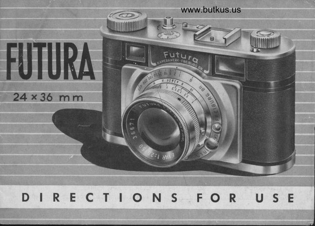
FUTURA User manual
User manual for FUTURA. 9 pages in English. Read the original PDF, download or print a copy without registration.
9 pagesEnglish4.9 MB PDF
Loading your manual…Open PDF directly
Document details
- Brand
- Futura
- Model / document
- FUTURA
- Document type
- User manual
- Language
- English
- Pages
- 9
- File size
- 4.9 MB
- Category
- Film cameras
- Document date
- Not specified in catalog
Search available document text
Find a term, then jump to its page in the original PDF. Image-only pages may not be searchable; check the PDF for exact wording and diagrams.
Page 3 · Read text
O fne insertion of the film in the usual        its end is inserted into a slit of the winri
daylightloading cassette for miniature    up spool and the approximately tln"
films is very easy. To open the camera      long end proiecting at the opposite side
a sliding button (0) is pressed in the       is sharply bent to avoid its slipping out
direction of the arrow (fig. {) and at the      of the slit. The cassette is inserted onto
same time the back side and bottom       the tappet in the left recess, the wind up
which are firmly connected, are removed      spool onto the tappet in the right recess
from the case. When 4" or 4aln" of the       of the case. Figure 2 shows how to close
film have been drawn out of the cassette       the camera: while the thumb of the hand
                                               whictr holds the camera slightly presses
                                          the film against the guideway, the other
                                         hand does not push the back wall upwards
                                         in its entire length, but mounts it as
                                     shown in figure 2 (photo). Now only the
                                      back wall may be slipped all the way
                                   up until a snapping indicates that the
                                            casing and the back wall of the camera
                                          are firmly locked by the spring catch.
                                         However, the camera is not ready yet
                                              Digitally signed by mike butkus  mike               DN: cn=mike butkus,            to take snapshots, because the section
                                    o=orphancameras, ou=29,
                                     email=mike@butkus.org, c=US
                                        Date: 2019.07.07 14:25:40 -04'00'  butkus
                                                                                                                                                                                                                                                                                                                                                                                                                                                            l
View original page 3Page 4 · Read text
www.butkus.us
                                                                                               >2<< thisof film pulled out when inserted into     By pressing the release button
the wind up spool has already been      procedure is repeated. Meanwhile the
exposed. It is necessary therefore to      rewinding button >7< should be watdted.
transport the film before taking any        If  it turns in the opposite direction of
picture. For this purpose the setting       the arrow the film is correctly transported.
knob >{< is turned in the direction of     But if after turning the setting button
the arrow until a resistance  is felt,  i. e. un-      the rewinding knob does not move, the
til a catch is activated, stopping the trans-      film must be inserted again. If this in-
port of the film after one picture's width.      struction is always strictly observed,
                                             there will never be any loading trouble.
                                  The counter >>3<< recording the number
                                          of exposures must be set to ZERO. It
                                      can be turned in the indicated direction
                                   by a slight pressure of the thumb.
                    @ fne tele-view finder is both view
                                          finder and range finder at the same
                                          time. In order to get acquainted with
                                                                                        it, an easy little experiment seems useful:
                            A sharply defined object in the vicinity
View original page 4Page 6 · Read text
v                      www.butkus.us                     ''.          -is sighted through the view finder. A       of the diaphragms are engraved on both
small section clearly contrasting by its      sides of the red triangle.
goid yellow tint will then be clearly     Here an example for better understand-
discernible in the finder. This section      ing:  After exact focussing the red
is made to move by turning lever >10<,      triangle shows a distance of 32'!0"  ;
and in a certain position it will be found       the diaphragm has been set to 8 by turn-
to coincide with the large image in the      ing the rim of the objective. Next look
finder. At this moment the exact range      for the figure 8 on the depth of focus
is automatically set. If this instruction      ring at the right and left sides of the
is observed for every shot the pictures
taken will always be sharp.

                                     >10<< isO fne setting le('er of obiective
already known to us, and fig. 3 shows
how to handle the camera when tele-
viewing. When the exact range has been
found, the number of meters is indicated
by the red triangle >42< and the depth
of field for all diaphragms is shown on
the depth of focus ring where the numbers
View original page 6Page 7 · Read text
red triangle. These two figures will be      non-cocked shutter. Only the U400 second
seen to limit the range from !.6' 5"     exposure makes an exception, as this
to co on the meter scale underneath,      should be set before the shutter is cocked
and this is the proper depth of field.    by the setting knob (1(. And now, a
If a larger diaphragm is selected, a.8.4,      slight pressure on release button >2(
the range will only reach ftom 22'11."     and your snapshot is taken. A turn of
to 72'2", and it vrill be noted that with       setting knob ,{<< up to the stop gets the
an increasing aperture of the diaphragm     camera ready for the next exposure.
greater attention should be paid to careful      For time exposures set ring >9<< to B.
focussing.                         Long exposures (>T<) are made by
                                          depressing and turning release button
@ fne shutter speeds are shown in        >2<< in the direction indicated. The shutterfractions of a second on ring r$<<. After                                                 will then remain open until the releasehaving found the exact time of exposure                                            button is turned back and flips up.ring >9<< is turned by means of knobs
))11(( until the corresponding number                                                                                     release                  @ tLt" of the uutomaticshows opposite the setting point on the                                              After setting the range and the time of
upper edge of the lid.                                            exposure, the setting lever >4( is turned
Alt exposure times from >B< to 4'/200     back to the stop and allowed to recoil
second can be set both with cocked or         (fig.  ). At the same time a white control
View original page 7Page 8 · Read text
www.butkus.us
mark will appear in the smaller window      with electrie ignition. The flashlight is
of the range finder. After a pressure on      syndrronized wirh all the shutter speeds
the release button a preliminary clockwork     and therefore guarantees snapshots re-
is actuated whidr will release the shutter      quiring short exposures only even in
only after about i2 seconds. The disap-     case of insufficient lighting conditions.
pearance of the control mark shows     The flashing device is either mounted on
that the shutter is in action.                                              the shoe of the view finder (S) or screwed
                                      onto the tripod thread (fig. {), and the@ ftug >6<fits everyflushlight equipment
                                             sleeve of the connection cord is placed
                                          Abb       onto the plug. In this case also direct
                                              release is effected by release button  >>2<<.
                              When finally 36 snapshots have been
                                          taken, which can be seen on the dial
                                              of the counter, the film must be wound
                                           back into the film cartridge. This is done
                              by strongly depressing button shown
                                           in fig. { at the left of the sliding button
                                    and by turning the rewinding knob >7<
                                         in the direction of the arrow until a
                                               resistance is felt. The camera can now
View original page 8Related documents and language editions


From the M. Butkus archive. Original publisher and archive notices are retained.
Check the model and edition against your equipment.
PDF verified 2026-10-10.