Film cameras
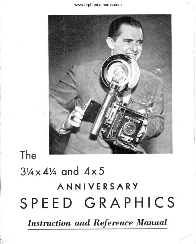
Graflex Anniversary Speed Graphic 3 1/4 x 4 1/4 and 4x5 User manual
User manual for Graflex Anniversary Speed Graphic 3 1/4 x 4 1/4 and 4x5. 37 pages in English. Read the original PDF, download or print a copy without registration.
37 pagesEnglish3.2 MB PDF
Loading your manual…Open PDF directly
Document details
- Brand
- Graflex
- Model / document
- Graflex Anniversary Speed Graphic 3 1/4 x 4 1/4 and 4x5
- Document type
- User manual
- Language
- English
- Pages
- 37
- File size
- 3.2 MB
- Category
- Film cameras
- Document date
- Not specified in catalog
Search available document text
Find a term, then jump to its page in the original PDF. Image-only pages may not be searchable; check the PDF for exact wording and diagrams.
Page 1 · Read text
www.orphancameras.com


   The
    3'/+x4'/o ond 4x 5
         ANNIVERSARY
  SPEED GRAPHICS
       Instruction and Reference Manual

i-
View original page 1Page 3 · Read text
www.orphancameras.com

                                                     1
                    A DESCRIPTIONOF
       YOURANNIVERSARYSPEEDGRAPHIC

  Your new  Anniversary  Speed GRAPHIC  is a camera  of the greatest
versatility.   Ii gives you a choice  of two shutters so thai you may enjoy
the greatest efficiency  whether you wish to make a very short exposure
or a relatively  long one. Focusing may be done by ground  glass, range-
finder,  or scale, depending  upon  the demands  of the subject and the
lenses used. Three distinct methods enable you to compose your picture
with the greaiest ease-for  most accurate composition there is the ground
glass; sliqhtly more convenient under some circumstances  is the tubular
viewfinder  which  has a correction  for parallax; and  finally  there  is the
wire frame  viewfinder  which many photographers  find  unexcelled  for
following  moving  objects.
  The  serial  nurnber    is stamped  into  the under  side  of the top of the
right  front  of the body as you face the camera and consists of six digits
about  fi"   high. Always  give  this number  in correspondence  regarding
your camera.
   Interchangeable   lenses  give  you  the  choice   of  focal  lengths  and
apertures so necessary for the many  fields of photography  in which  this
camera  is capable  of working.  Double  bellows  extension  aids  in  the
photography  of small objects and  in the use of long-focus  lenses. The
drop-bed  will be readily  appreciated when   it becomes necessary to use
wide-angle  lenses as in the photography  of architectural  subjects, and
on ihese and other occasions the movements  of the front standard  will
also be valuable.
  Accommodation  can be provided  for the use of flash synchronizers,
an expedient  which  has been known  to make the dilference  between
 good pictures and no pictures on many occasions.
  The choice  of negative  materiais-including     film  packs, sheet  film
 and plates-is   equalled  by but few cameras. And  finally,  and perhaps
most important,   all these features have been  accomplished  withoui  a
 sacrifice   of  rigidity   or  without  a departure   from  good  photographic
 manufacturing  practice.
View original page 3Page 4 · Read text
www.orphancameras.com

2

         A fine camera is primarily an instrument rather than a machine.GRAFLEX
          products have won a reputation  for sturdiness and continued  function-
           ing under adverse conditions, but  this should in no sense be considered
 '         an invitation  to abuse these cameras. More damage  is probably done by
          people  handling  things  wlth which  they  are not  familiar,  than by the
          normal wear of service. To insure the long and trouble-free  life of which
          your camera  is capable, follow and study these directions as you handle
                   it for the first time. Above  ali, do not twist any knobs or push any buttons
         on this camera  until you know what  this pamphlet  tells about them. Do
           not lend your camera  to anyone not familiar  with  it, or without  instruct-
           ing him  in how to use  it.  If you Iose ihis book or want addiiional  copies,
           write us.
OPENINGTHECAMERA

           The preferred way to open the camera is to rest it on the left hand with
           the viewfinder  on the iop, and the thumb  of the left hand inserted between
           the carrying  strap and the camera body. Press inward on the front (bed)
           with  the  right  forefinger,  and  at the same time depress the bed  release
          button   with the thumb. As the bed then opens downward,  its fall may be
         checked by the righi hand. Continue  firmly but gently  to bring  the front
        down  to the point where  the spring-actuated  bed braces  lock the bed
            firmly  in  its horizontal  position.
            Turn the knurled  focusing  knobs  located near the front edge of the
         bed to move the sliding   track.  This is the focusing   adjustrnent   and
              will be considered  in more detail  at a later point. The front  standard
           rests on the  sliding  track,  and   it  carries  the  lens with   its associated
            shuiter. To loosen the front standard, turn the front  standard   lock,  so
            that   it  is parallel  io the  track.  Unlock  and move   it along  the  sliding
            track,  pulling    it past the  flat springs,  until   it snaps firmly  against the
             infinity   stops.  Lock the standar-d by taking  the locking  lever and the
           side of the standard  between  the thumb  and the index  finger  and push
           the lever back by squeezing. This will keep the front standard firmly  in
           position. Always  lock  the  standard. The lens with  which  this camera
         has been  fitted  at the factory  will  then be in position  for focusing  with
            either  rangefinder   or focusing  scale.
View original page 4Page 5 · Read text
www.orphancameras.com

                                              3


            www.orphancameras.com


 RlS lt{ c FRONTi  r
    L O C K N U T  ;


                   BRACE
                      FRONTBED


Figure  1. The 4 x 5 Anniversary  Speed Graphic,  with the 127 lonrra.Graflex  Optar, elements
coated,  in  Graphex  Shutter  with  built-in  synchronization  with  accessory  rangelinder  and
  Graphex 37FA Flashing Unit. The 3 Y+ r 4Y+ Model  is practically  identical except lor size.
View original page 5Page 6 · Read text
www.orphancameras.com


          To  close  the  carnera,  rack  the track  all of the way back  until  the
          focusing  scale indicates  the infinity  position. Unlock  the front standard
         and push  it  all of ihe way back  into the camera and lock  it. Leave the
           track  lock unlocked  and depress the bed braces and push up the bed
             until  it snaps securely.

SHUTTERS
               .   The Speed GRAPHIC  Camera  is usi.rally provided  with two shutters.
          For slow exposures (durations longer  than perhaps  l/50th  of a second)
         and  for synchronized   flash photography   with  the  larger  size negatives
         and  existing  lamps,  a between-the-lens shutter is  still  preferable.  The
           shutter  built around the lens of your Anniversary  Speed GRAPHIC  is an
           excellent  example  of this iype. For action  requiring  exposures  shorter
          than about  l/50th  o{ a second, the focal-plane  shutter has never been
         surpassed in efficiency.  And no focal-plane  shutter has ever surpassed
           that in your Anniversary  Speed GRAPHIC  in dependability.  Naturally
          only  one  of these  shutters   can  be used  at  a  tirne;   the  one  not
          being  used  rnust  be  set  open  during   the  exposure   (as will  be
          explained  below).
          The front shutier  is kept from rotaiing on the lensboard by a iocating
           pin  fitting  into a hole in the lensboard. Should  it be necessary to remove
          the shutter from the lensboard to fit a solenoid release or for other reason,
             .    first remove the flange from the back  of the lensboard.
         Some shutters have  built-in  contacts  for  synchronization  with  hiqh-
         speed gaseous discharge  tubes and some also provide  for synchroniza-
            tion  with  differeni  types  of  flash lamps.  Detailed  instructions  for  the
          various shutters appear on the {ollowing  pages:
           Most flash lamps have a lag of either  five or iwenty  miliiseconds and
          they are referred  to as type "F" and "M"  lamps as indicated  in the follow-          *I           ing  table:
                                    5 Millisecond         20 Millisecond
                                                                                                                                                                           i                                 Type "F"  Bulb        Type "M"  Bulb
                                       (qas filled)           (wire or foil  filled)               I
          G-E and Westinghouse     SM       No. 22, No.  Il,  No. 5, etc.
          Wabash                   SF       No. 2, Press 25, 40,  elc.

                                                                                                                                                                              I
                                                                                                                                                                                                                                                                                                                                                                                              ld
View original page 6Page 7 · Read text
www.orphancameras.com

                                                     5
                THEGRAPHEXSHUTTER

  DIRECTIONS:   The No. 2 Graphex  shutter is rim-set, with 9 speeds
from 1 to  I l4OO second plus Bulb  and Tirne.  The knurled  rim  carries
the designations T, B,   I,  2, 5, 10, etc., (the numbers corresponding  to
instantaneous expcsures of  I,  I12, L15, t/10  sec., etc.) and the desired
one should be set directly  opposite the arrow above the letter "P"  of the
word Graphex.
  The speed setting may be changed before or after cocking the shutter,
but  is more  easily accomplished  before  cocking.  Settings between  the
marked speeds will not  give intermediate  exposure times. When  turning
the knurled  rim to  I l4OO a slight additional  pressure  will be required  to
overcome the resistance of the booster spring.
  As illustrated the cocking   lever  is at the upper  left side of the shutter.
Moving  this lever clockwise cocks the shutter. After the shutter has been
cocked, the lever returns almost to its original  position, but exposes a red
dot, indicating  that the shutter has been cocked.
  The release  lever  is at the bottom  of the shutter. Pressing toward  the
right or inward on the Finger  Release,  if one is fitted to the camera, with
the forefinger  will release the shutter mechanism.
  The Graphex  shutter  is cocked  in the usual manner  for  Tirne  and
BuIb,  as well  as instantaneous exposures. When  set on  T,  the  first
pressure on the release opens the shutter,
and the second permits  it to close. When
set on B the shutter remains open only as
long as pressure is maintained on the re-
lease. A cable release and tripod should
always be used  for Tirne  and Bulb  ex-
posures.
  The cable  release  socket   is next  to
the cocking  lever. The aperture   scale
and aperture   pointer  are at the bottom
of the face of the shutter.

         Figure 2a. The l2Trnrn Kodak Ektar Lens
                    in No. 2 GRAPHEX Shutter with
                              built-in   synchronization.
View original page 7Page 8 · Read text
www.orphancameras.com

6

           The Press-Focus   Lrever,  at the top of the shutter, may be used for
            '          opening  the cocked  shutter   blades  for focusing purposes, eliminating
           the necessity of resetting   it to the Tirne  setting for that purpose. Move
           the Press-Focus Lever clockwise and down  to open the blades; move   ii
          counter-clockwise  and up  to close them.  This  lever  will  not  function
             .i:  unless the shutter  is cocked, and does not interfere   in any way with  the
          ,    normal  operation  of the shutter..,
FlashSynchronizationwith GraphexShutters
           The two contact  posts extending  from  the side of the shutter  are con-
          nected  to an internal  switch.  in  the GRAPHEX   (X) Shutters  (identified
         by a large  "X"  next  to these posts), the contacts are for use only  with
          high-speed gaseous discharge tubes. When using these be sure to obtain
               full wiring  or circuit  data from the manufacturer  of the lamp. Synchroni-
           zaiion with standard flash bulbs  is effected through  the use of a solenoid
           or other external synchronized  tripper.
          .      Those GRAPHEX  Shutters wiih  a dial  setting arrangement,  shown  at
           the right  in Fig. 2a, have a special gear  train providing   built-in   syn-
           chronization.    This gear  train  is automatically  engaged  as the shutter
          iscocked unless the notched synchronization  control lever has been moved
            to the "OFF"  position. Should the shutter aiready be cocked before mov-                                                 r\O"           ing  the  control  lever  from  the         or        or  "OFF"   positions  to
           other positions, the synchronization mechanism  will not be cocked unless
           the shutter  itself  is released and recocked;  hence,  in such an instance
          recock  the shutter  to cause the synchronization  mechanism  to be  en-
          gaged. The control  lever  of the dial  setting arrangement  on the side o{
           the shutter has click stops to permit accurate  setting for synchronization.
        Make certain that the stop is definitely engaged  in its detent before cock-
           ing the shutter. The control lever adjusts the delay of the operation o{ the
           shutter to correspond with the correct ignition  lag of the lamp being used.
          Set the lever to the "20"  or "M"  position on the dial to synchronize  the
           shutter with standard wire  or foiljilled   flash lamps such as the G-E and
         Westinghouse  Nos. 22,   Il  and  5, and the Wabash Nos. 2, 0, Press 40
         and 25 lamps. Set the lever to the "5"  or "F"  setting to synchronize the
           shutter  wiih  ihe  gas-filled SM and SF lamps. When  using high-speed
         gaseous discharge  tubes, set the lever  at the "O"  or "X"  setting, and
           follow detailed wirino  or circuit hookup data for use with the shutter from
           the manufacturer   of {he tube.
           To use the  built-in  synchronization,  attach  the flattened  right  angle
          connection  of the A-20  connecting   cord  to the coniact  posts on the
           shutter as shown  in  Fig. 2a, and plug  the oiher end  into the SERIES
        OUTITET  at the back  of the battery  case. In the GRAFLEX Flash Syn-
           chronizer  Battery Case, this outlet is reached by unscrewing  and swing-
           ing down  the  red push  button  switch.  The  shutter  is  released  and
          synchronization  is effected only by the operation  of the release lever as
           outlined on preceding  page.
View original page 8Page 10 · Read text
www.orphancameras.com


                 If desired, a cable  release may be used to operate the shutter. Unscrew
          the cable release screw plug located next to the release lever and aiiach
          the cable release  at that point. A cable  reiease and a tripod  or other
           firm  support  should  always be  used  for  Iong  instantaneous  and  all
          "Time"  and "Bulb"  exposures.
          The Press-Focus   Button,   just over the numeral   I on the shutter speed
           scale, is used to hold the shutter blades open for ground  glass focusing
          without  resetting the shutter to "T".  with  the shutter set for any speed
         and cocked, hold down  the Press-Focus button as you press the shutter
          release  lever. The  shutter  blades  will  then open and remain  in  this
           position. To release ihe Press-Focus button, and make ihe shutter ready
            for the exposure, merely recock the shutter with the cocking  lever. The
           shutter  will then operate in the normal manner when released.
         Some of the No. 2 and  all of the No. 3 Supermatic  Shutters have the
         delayed  action  mechanism.  This has its own cocking  lever (above the
            letter  "T"  on the speed scale), which  is moved  to the right away from
          the  Press-Focus Button  only  after  the  shutter has  first been  cocked.
         Pressure on the shutter release lever  wili release this additional mecha-
           'nism, and  it will  automatically make the exposure  after a delay  of lO io
            I5 seconds. This device can be used when the phoiographer  wishes to
          get into the picture  himself, and will release the shutter without  iar when
          slow speeds must be used with the camera held  in the hand.
FlashSynchronizationwith SupermaticShutters
           The two contact  posts extending  from  the side of the shutter  are con-
         nected  to an internal  switch.  In the Supermatic  (X) Shutters (idengfied
         by a large  "X"  after the word  "supermatic"),   the contacts are for use
          only  with  high-speed  gaseous discharge  tubes  (Kodatron,  etc.) When
          using these be sure to obtain  full  wiring  or  circuit  hookup data for use
          with  this  shutter  from  the manufacturer   of the  tube.  Synchronization
          with  standard  flash bulbs  is effected through  the use of a solenoid  or
          other external synchronized  tripper.
            Supermatic  shutters  with  a slot  in  the  fact  plate  next  to the contact
          posts are complete  wiih  .built-in    synchronization    mechanism  per-
           mitting  internal  adjustment  to synchronize  the action  of the shutter  with
           different  types  of  flash  bulbs.  The  Supermatic  shutters  with  built-in
          the lever which was used to cock the self-timer in previous mod.els is now      {+
           referred  to as the synchronizer  lever and   it must be moved  clockwise                 .i
         as far as possible to cock the built-in  synchronization mechanism.  Other-
         wise the {lash bulb will not be f ired when the shutter is released. Set the
          binding  screw  in the slot in the face of the shutter to the "20"  or "M"
           position to synchronize the shutter with standardwire or foil-filled  f lash lamps
                                                                                                                                 II
View original page 10Page 11 · Read text
www.orphancameras.com
                                                 9

such as the G-E and Westinghouse Nos. 22, 1 I and 5, and the Wabash Nos.
2,0, Press-4Oand 25lamps. Setthe screw to the "5"  or "F" setting to syn-
chronize the shutter with the gas-filled SM and SF lamps. Afier loosening
the screw and moving  the indicator   to the desired  position,  tighten  this
binding  screw securely. Set the aperture  pointer, adjust the shutter speed
ring, and cock the shutter as usual. Push the synchronizer  cocking  lever
(previously  used to cock  the  self-timer) toward  the two prongs on the
shutter rim as {ar as it will  go. The  shutter  is ready  to provide  positive
flash lamp  synchronization  when  the  shutter  release lever  is pressed.
CAUTION:  Do not use the Press-Focus Button without  first disconnecting
the connecting  cord  or removing  the flash lamps.
  When  using the Kodatron    or other speed lamp, do not use the syn-
chronizer  cocking  lever, since the mechanism  is automatically  in adjust-
ment and contact  for such lamps  will  be made when  the shutter  blades
open.  Obtain  complete  wiring   or  circuit  hookup  date  for use with  this
shutter from the manufacturer   of the lamp.
  To use the  buiit-in   synchronization,   attach  the  flattened   riqht  angle
connection  of the A-20  connecting    cord  to the contact  posts on the
shutter as shown  in  Fig. 2a, and plug  the other end  into the SERIES
OUTITET   at the back  of the battery  case. In the GRAFLEX  Flash Syn-
chronizer  Battery Case, this outlet  is reached by unscrewing  and swing-
ing down  the red push  button  switch.  The shutter  is released  and syn-
chronization    is effected  only  by  the  operation   of the  release  lever  as
outlined on page 7.
                 THECOMPURSHUTTER

   All  ihree  types  of Compur   shutters  with  which  a Speed GRAPHIC
may be equipped  are fundamentally   similar  to the following  extent:
  They are built around  the lens, and contain  its iris  diaphraqrn    (by
which you set the stop or aperture of the lens); they produce  the conven-
tional Time and Bulb exposures without  "cocking";  and automatically-
timed  Instantaneous  exposures  from    I  second  to  something  shorter
than l/IOOth  of a second after "cocking."
    It must be cocked  to produce  an instantaneous exposure, and  this  is
done by moving  the cocking   lever  clockwise  until   it catches.  After
cocking,  the shutter  is released by moving  the release  lever  counter-
clockwise  or squeezing the cable  release  that may be screwed  into the
cable  release socket.  When a shutter  is set for T, the first pressure on
the  release opens  the  shutter,  the second  closes  it. When  set at B,
pressure on the release will open the shutter leaves, and relieving  this
pressure  will permit  the leaves to close.
  Never attempt to cock a Compur shutter when it is set f or T or B.
  Neyer attempt to move from an instantaneoussetting to T or B while the
shutter is cocked.
View original page 11Page 12 · Read text
www.orphancameras.com
10

The Rim-SetCompur
           The Compur  shutter  illustrated  in Figure  2c  is referred  to as being
            of the  "rim-set"   variety,  because  the  choice  between  the exposures
         which    it  is capable  of giving   is made by  rotating  the knurled  rim.   It
          carries the designations T, B, 1,2,5,  I0, 25, 50, 100, etc., (the numbers
          corresponding  to instantaneous exposures of 1,  I 12, I /5, 1/I0  sec., etc.)
         and the desired one should be set directly  opposite the arrow  (which
          points  at  I00  or  l/I00,   in the  illustration).  For any exposure except
         T and B, the cocking  lever  is rotated as far as it will go in a clockwise
           direction  after setting the speed. Never attempt to change from or to the
          highest shutterspeed while the shutter is cocked.
           The working  aperture  of the lens  is set by moving  the pointer  of the
         diaphragm  control along the scale carrying  these aperture designations
                                             on the face of the shutter.
                                                             In the case of this rim-set shut-
                                                                 ter, a delay of approximately  ten
                                             seconds  in  the  release  of  the
                                                      shutter will automatically be pro-
                                            duced    if,  after  the  shutter   is
                                               cocked, the delayed action  but-
                                                    ton  behind  the cocking  lever  is
                                        moved  back  and  the  cocking
                                                       lever  is then pushed  still farther
                                                           to  the  riqht.  Pressure  on  the
                                                   release lever or the cable release
                                                                 will actuate the delay mechanism,
                                            and  after approximately  ten sec-
                                             onds the shutter itself will operate
                                            and make the exposure. To pre-
                                                   vent damage  to the  shutter  this
                                              delayed-action  mechanism must
                                             never be used with  the highest
                                                     shutterspeed.
    Figure  2c. The Rim-Set Compur   Shutter.
The PressCompur
            This shutter, supplied  only with the Carl Zeiss I3.5 cm and 15 cm
         Tessars 114.5,is a modification  of the "rim-set" Compur.  It differs in that
           the delayed-action mechanism  is replaced by a catch  to hold the shutter
View original page 12Page 13 · Read text
www.orphancameras.com
                                           11

 Ieaves open  for ground-glass  focusing,  in the same way as the Press-
Focus Button does in the Supermatic  shutter.
  To hold  this shutter open,  trip   it (when  set for any speed) with  the
catch  button   held back, and cushion the cocking  lever  with the finger
so  it  will  not  strike hard  against the catch;  this  will  retain  the shutter
leaves  fully opened  for focusing  on the ground  glass. After  focusing,
re-cock  in the normal manner  for the actual exposure, and the catch
button  will release  itself. This catch button replaces the self-timing  but-
ton. The self-timing mechanism has been removed from this shutter.
                            The Dial-SetCompur
  The chief  difference  between  the  "rim-set"  and the  "dial-set"  Com-
pur  lies  in the speed selection meehanism. The function  of the knurled
rim  of the former  is divided  be-
tween the two dials in the latter.
   With T (sometimes Z) or B of
the  smaller   dial   (the  locking
disc, between the shutter release
Iever and the cable release sock-
et)  set opposite  the  short white
line  carried  on  the  face  of the
shutter, operation  of the release
lever  will produce  Time or Bulb
exposures without cocking. When
the  I (sometimes engraved M)  of
this  small  dial  is turned  to the
short white line, the instantaneous
exposures shown on  the  larger
speed dial  will be produced  after
cocking  the  shutter. The speed
dial  (carrying  the choice  of  in-
stantaneous  exposures)  has  an
arrow engraved  on  its front  sur-
face to show the direction  in which                  Figure  2d. The  Dial-Set  Compur   Shutter.
it is to be  turned  in changing  speeds. Never attempt to rotate this dial
against the arrow,  or the mechanism  will be damaged.
  The working  aperture of the lens is read against the scaie carried on
the top side of the shutter behind  the speed dial  or on the face of the
shutter, and controlled  by a lever  at the base of the shutter.
View original page 13Page 14 · Read text
www.orphancameras.com
19
FOCAL.PLANESHUTTER


                      The  focal-plane  shutter with  which  this camera  is pro-
                        vided  consists essentially  of a durable   liqht-tiqht   curtain
                          (Figure  3)  having   five  rectangular   openings   or  slits,   a
   0-'xr!t 0Pil{
                     chosen one of which  passes in  front  of the  film  or plate  in
                     making  an exposure.  The  portion  of the  curtain  which   is
                         not covering  or exposing  the negative   is wound  on rollers
  A.l0 to 40                at each end, and in making  the exposure passes down from
                         the top to the bottom  roller.  The exposure  time  is governed
  B'?0 ro 150            by the width  of the  slit  and by the tensions   of the spring
                      which  causes the curtain  to move when  the mechanism  is
                        released. The  front   shutter    rnust  be open  on  Tirne
  C-200ro{00
                    whenever   the  focal-plane   shutter    id used.

                      The  controls   for  the  focal-plane   shutter  are  located  on
  D.100n 1000            the right side of the camera housing  (as,normally used from
                        the back), and appear as in Figure  4.
                      The  Shutter Speed lab/e  on  the  top  of the camera  in-       I
                        cludes  numbers  representing   exposure  times  customarily                                                                                                                                                                                                                                                                                                                                                         IiI
        Fis.3.           re{erred to in terms of fractions of a second, obtainable  with                                               it,
    The Curtain.
                        the various combinations  of curtain  apertures A, B, C and
                D and tension numbers    I throuqh  6.

           These reference  letters and numbers  are changed  progressively  from
      O to D  in the  slit  aperture  window  by turning  the shutter-winding
         hey counier-clockwise,  and from   I to 6 in the spring  tension  window
         by turning  the spring  tension   control   counter-clockwise.  In so doing,
          progressively  smaller  slits and higher  tensions are made  available  for
          the exposure.  To reverse  either  operation  and  return  to a wider   slit or
         lower  tension than  indicated,  the shutter release or tension release  is
         moved,  to allow the mechanisms  to unwind  one notch  at a time.  It will be
         found easier to set io a higher  tension before winding  to a narrower   slii.
View original page 14Page 15 · Read text
www.orphancameras.com

                                           13

  When the shutter hag been set in accordance  wlth the above direcgons,
the exposure  is made by carefully  sgueezing the shutter   release  or the
plunger  of the cable  release.  Avoid  jarring  the camera.

  To make a time exposure with the focal-plane  shutter, wind or release
the curtain  until T  (Time) appears  in the  slit  aperture   window.   Set
the tension at  I  ; rest the camera upon a rigid  support; open the shutter
with one pressure upon  the release, and terminate  the exposure by a
second pressure.

  This shutter can be locked  in any  position by moving  the shutter
lock  button   toward  the rear  of the camera.  It  will be unlocked  auto-
matically when the shutter winding  key  is turned  again. Always  lock  it
on O when using the front shutter.


                                CAUTION:  Becauee one  of the
                                           curtain  slits passes in front of the
                                           picfure  aperture  every  time  the
                                           curtain  is moved  (either in wind-
                                          ing   it  or  in  releasing   it),   it  is
                                    necessary to protect any   f iln  in
                                        the  camera from  unintentional
                                    exposure by having the slide  in
                                        the  film holder  while  the  focal-
                                      plane shutter  is being  set; other-
                                      wise injurious  fogging  of the film
                                                    is liable to result.

                                                    *


                                                     Figure   4.
                                              The  Focal-Plane   Shutter   Control   Panel.
View original page 15Page 16 · Read text
www.orphancameras.com

1 4
FLASHSYNCHRONIZATION
           The Speed GRAPHIC  Camera can be used for flash synchronization
          through  either  of two systems. Some shutters are complete  with  built-in
        mechanism   automatically   producing   synchronization.   Complete   in-
           structions appear on pages 4, 6 and B.
            With a shutter having  built-in synchronization,  the required accessories
              will be in the nature  of a flashing  unit consisting  of a battery  case, re-
             flector,  battery case support and a cord extending  to the shutter. This
          cord should be attached  to the shutter and  to a Series  Outlet   in the
           battery case. This outlet  is usually  at the back of the battery case, some-
          times on the underside  of the head.  In the GRAFLEX Battery Case,  it is
         beneath the red push button switch and is made available by unscrewing
          the  switch  and  swinging    it down.  Other  shutters require  a complete
          synchronizer  consisting  of the battery case, reflector, solenoid or shutter
           tripper and suitable connecting cord.
          A battery  case, carrying a reflebtor  and socket for the lamp, is usually
          attached  to the camera by means of a suitable coupling  on the range-
           finder   encircling   bracket  shown  in Figure  8. A rnagnetic   release,
        whose function  is to release the shutter  at the proper  instant, must be
          properly  positioned  in relation  to the release lever. With  most shutters
          the Solenoid Release of the GRAFLEX  Synchronizer may be left perma-
           nently on the lens board.
           To operate  the synchronizer  after  it is in place, the focal-plane shutter
              is first opened by setting O  in the slit aperture window, the front shutter
             is  set  for one  of  its  highest  speeds
         and cocked,  a  flash lamp   is  inserted
             in the socket, and the button  for  clos-
           ing  the  circuits  on  the  rear  of  the
           battery  case  is pressed  to make  the
          exposure. With a correctly  adjusted out-
                 fit using any flash lamp designedf or be-
          tween-the-lens  shutter synchronization
           the shutter  will be opened and closed
          while  the  flash  is at  its maximum  in-
            tensity. Recommended  lens  apertures
         and shutter speeds should be obtained
          from tables furnished  by makers of the
         Iamps.

                 Figure   5, The GRAFLEX   Flash  Synchronizer
View original page 16Page 17 · Read text
www.orphancameras.com

                                              ?                                                                  1 5
                      Ground-GlassFocusingfor Flash
  When  a magnetic  release  is  in  place,  its finger may be  in such a
position  as to make the front   shutter  inoperative   for either Time or Bulb
exposures. As far as the flash synchronizer  itself is concerned  this  is of
no importance,  but   it may be exceedingly  annoying  when  ground-glass
focusing must immediately  precede  use of the flash. This difficulty  has
been overcome  through  the introduction    ol the press focus button  and
press focus lever built-into  the Supermatic, GRAPHEX and press Compur
Shutters, previously  described.  In other shutters  it may be necessary to
remove the tripper  finger  or link.
                            LENSES
  The lens of your Anniversary  Speed GRAPHIC   is mounted  in a shutter
incorporating  an  iris  diaphra€tm,   and  the  shutter  is screwed  into a
metal flange  attached to the lensboard.  The lensboard  is held  in place
in the front standard by slide  lochs. Each lens should have  its own lens-
board.
  To remove  the lensboard, move the slide locks  in the direciion   of their
slots, holding  the board  at ihe iop  to prevent  its falling  out. Then  lift  it
oui by grasping  the shutter.
  The 3vtx4ve   Anniversary  speed GRAPHIC  has slide locks top and
bottom,  while  the 4 x 5 model has a slide lock on the top only.
  The diaphragm    scale  (aperture   scale  in Figures  2b, c and  d)  is
marked  in   f/  numbers,  indicating   the  relative  sizes of the  operring,
secured by moving the diaphragm  control  lever. Full information  orr this
subject  will be found on page 25 under the heading  Correct Exposures.
  Your camera, when  fitted  with a lens whose focal length  is approxi-
mately egual to the diagonal  of the negative,  will give a "normal"  angu-
lar coverage or field  of view-that    is, about 45.  to SO".
  To photograph  large objects at close range you can use a wide-angle
lens-an   objective  of relatively  short focal length but specially desiqnld
to cover  the negative.  The image  of each  object  will  be smaller  at a
given distance with a wide-angle  lens than with a normal  lens, but there
will  be a wider   field  of  view.  (see  under  The  wide-Angle   Lens  for
{urther  information.)
  For a larger image of objects at a distance, use a long-focus   leng or a
telephoto.   The latter type  is sometimes preferable,  because  it does not
reguire  so great an increase  in bellows  extension and  still gives a larger
image.  Needless  to say, the  field  of view  of a long-focus  or  teleph-oto
lene ig smaller  than  that  of a normal  focal  length.
View original page 17Page 18 · Read text
www.orphancameras.com
16

              other  things  being  equal, a wide-angle   (ehort-focus)  lens  will  have a
           greater  depth  of field  and angle  of view  ihan  the normal  focal  lengih,
           while  long-focus  and telephoto  lenses have a smaller  depth  of field and
          angle of view.                                                                                  l-r
            Equal   f/ numbers  have  the  similar  values on  all  lenses, regardless             t-            of focal length.
COATEDLENSES                                            4I
           The  coating  of lenses  is one  of the most recent  accomplishments   in
     .       the  optical  industry.  A  coated  lens  will  have a brownish-purple    color
         on the surface. This color  is similar  to the tarnish  or iridescent  color
            that was  previously   considered  detrimental   in  lenses. The  process  of
           coating  deposits  a metallic   salt, such  as magnesium   fluoride,  on  the
          surface  of the lens  in an extremely  hiqh vacuum.
           The coating  of lenses is done only on the air glass surfaces and not on
           the cemented  surfaces. The advantages  of coating  photogiaphic   lenses
          are an increase  in transmitted   light  by a reduction   in  light  loss caused
         by  internal   reflections,  a definite  increase   in  brilliance   or  contrast  of
          the image and  the elimination   of flare  spots due  to multiple   reflections
           within  the lens. Every surface  of a lens that  is coated  will  increase the
            light  transmission.  However,  with  most standard  lenses, this increase
            in  liqht transmission  will  not be noticeable due to the exposure  latitude
           of most of the films currently  available. The added  brilliance  due to the
          coating  of the lens surfaces should be noticeable  and should  result  in
            finer  photographs.
          The coating which  is now being  applied  to lens surfaces is almost as
          hard  as the  average  optical  glass.  While  no  special  precautions   are
         necessary  for  cleaning  the surfaces  of coated  lenses, they  should be
         handled  as carefully  as all fine lenses. AII surface  grit and dust should
              first be removed with a soft camel's hair brush before the lens is cleaned
          with  a fine  lens tissue or a soft cloth such as a well-laundered   linen
          handkerchief.  Do not  apply  pressure  on  the  cloth.  simply  breathe  on
          the surface of the lens and wipe gently  with easy circular  motions.  If a
          lens cleaninq  fluid  (only those specifically recommended  by lens manu-
           facturers)   is  to be  used, do  not  apply    it  directly  on  the  lens  surface.
          Instead place a drop  or two on the lens iissue or cloih and wipe  the lens
           with  the moietened  material.
View original page 18Page 19 · Read text
www.orphancameras.com

                                                     1 7
                         FOCUSING
   The focusing  scales on Speed GRAPHIC  cameras  are of the vernier
  type, one part carried  on the camera bed and the other on the sliding
  track. The distance indicated  is that from the subject to the film or grorrrrj
 glass. To focus on any desired distance,  iurn the focusing knob until the
 lines corresponding  to that distance on the two parts of the focusing scale
  Iie exactly next to each other. when  the front siandard has been pulled
 against the  infinity  stops and locked and the lines opposite the  infinlty
 marks (oo) on the two scales coincide,  the camera-will  befocused on
 very distant objects  (infinity). To focus sharpiy on an object l0o  feet from
 the ground  glass, for example,  turn  the focusing knobs  until  the lines
 marked 100 on each scale coincide  as shown in Figure  6.
   To factlitate guick use a modification  of this scale is shown in figure 6.
 For the shorter distances the single  indicator  line on the movable scale
 can be set opposite the desired footage mark.
  when  several lenses are to be used interchangeably  a new  vernier
 scale musi be fitted for each  if this meihod  of focusing  is to be used.
  The tracks  are easily moved by means of the focusing  knobs  as long
 as the track-iock  points front. Turning  the lock leverco  thut  its free end
 points toward the nearest knob, locks the focusing mechanism.
  Ground-Glass   Focusing  must naturally  be done with both shutters
open  (as in making  a Time exposure  as descrrbed  in  the section on
Shutters), and preferably  with the camera on a tripod and the lens set
at its maximum aperture. The(ground  glass i.s made
accessible by  pulling down on the small latch   in
Figure B, which allows the focusing  panel  cover to
spring up. After use, this hinged door is pressed back
into  its closed position  to prevent damage  to  it or to
the glass focusing screen. Accurate  focus on the
ground giass screen can be obtained by varying the
posiiion of the lens with either focusing control knob.


                             ligure   6. The Veruier Focuriug  Scale.
View original page 19Page 20 · Read text
www.orphancameras.com
18

          The focusing panel in a GRAPHIC  Back recedes to permit the en-
         trance of a GRAPHIC Film Holder or Film Pack Adapter so ihat the film
            will lie in the focal plane where the image is formed.
                   If your camera has a GRAFITEX Bach,  it will accept the GRAFLEX         focusing panel  interchangeably  with  the GRAFLEX film and  plate      I
         aitachments.                          $
RangefinderFocusing
             This camera,  as illustrated,   is eguipped  with an accessory  internally-
          coupled  rangefinder.   Before leaving  the factory   it was adjusted so as
      .       to synchronize   (i.e. give an exact indication  of critical  focus) with  the
            particular   lens  with  which  your  speed GRAPHIC  was equipped.  Any
         change  in  lens, even   if the focal lengths  are nominally  the same, will
           require  a checking  and probable  readjustment  of this rangefinder    if  it
             is to be used for the most accurate  focusing. Such a re-synchronization
          should be attempted  only by one with  such experience;  and then  only
             in accordance   with  the procedurb  recommended  by the manufacturer
            of the accessorv.
           To use the ranqefinder  look through  the small window  in  its side near-
           est the back  of the camera  (or through  the extension   eyepiece  attached
           to the  rangefinder),  being  sure  to keep  fingers  or  other  obstructions
        away  from  the two windows   in  its  front  side. Move  the camera   until
           the object  to be focused on is in the center  of the field  visible  through  the
          rangefinder.  Careful examination  will now reveal a smaller and brighter
             fleld  in approximately   the center  of the larger  one, and this smaller  field
           contains  a second image  whlch  can be shifted by turning  the focusing
           conhol.  A  little  practice   will  enable  you  to lotate  the small  field  in the
          exact center  of the larger one without  conscious  effort, and  this exact
          centering   is necessary  to the most accurate  use of  this accessory. A
             critical  focus is indicated  for that object or portion  thereof which shows
         a single image in this central  field of the rangefinder. A double image  is                                                                  i           indicative  of "out  of focus," and may be corrected by turning  the focus-
           ing  control   in  the  proper   direction.  Whenever   possible,  rangefinder          focusing  is facilitated  by picking  a portion  of the object  which  presents     f
          sharp  lines  of good  contrast.
            Althouqh   this rangefinder   is a great convenience   in focusing,    it does
          not  tell you the exact amount  of the scene which  will be included  on the
          negative.  That  is the  function   of a viewfinder,    described   in  the  next
           secflon.
View original page 20Page 21 · Read text
www.orphancameras.com

                                                19
                              VIEITFINDERS
            Three methods are available to the user of a Speed GRAPHIC  for know-,l         ing how much of a given scene will be included  in the negative. For most
          purposes the tubular   viewfinder  mounted on top of the camera near the
{          rangefinder  will be used. Details of the means by which  this finder can
          be adjusted  for parallax  and for different  focal-length  lenses are shown
              in Figure  7. The small dial  at the back  of the finder has four markings,
          which can be aligned with the white  line at the top of the finder. Notches
            assist in  locating  the  four
           points so that subjects at dis-
          tances of  6' , B' ,  15' and B
              (infinity), respectively will be
           centered by the camera lens
          on the ground  glass when
           the  subject  is centered   in
           the finder. When  using the
             finder,  set this  dial  for  the
           distance to the subject.

                                                                              Figure   7. The  Tubular   Viewfinder.
           Caution:  Be sure that the front standard  of the camera  is centered  lat-
             erally and vertically.
           The size of the front  aperture   in this finder determines the maximum
              field of view seen through   it, and may be changed by the insertion of new
          rnasks  to correspond with the fields covered by lenses of various normal
         and long focal lengths. The mask supplied  with the camera was chosen
            to match the lens fitted  to  it. Each mask is identified  by a number, and
          data concerning  their use will be found  in a special circular  available
         on request.
           The wire  frarne  finder   is brought  into action by raising  the peep-
            sight  from  its folded  position  against the rear  of the camera  top, and
          by extending  the frame  from  its telescoped  position  behind  the  front
           standard.  This extension  is accomplished  by grasping  at  its center  the
          upper  of the two horizontal  rods lying  along the top of the front standard
         and  pulling    it  directly  upward   until  both  bars  are  raised.  This  finder
View original page 21Page 22 · Read text
www.orphancameras.com
90

         must be collapsed again before the front standard can be returned  to the
         camera  housing  preparatory   to folding  up  the bed;  its  vertical  sides
          telescope into the collapsed position when  its top horizontal member  is
         pressed evenly  at each end in a downward  direction.  This wire frame
           finder  permits you  to observe the picture  full-size and from eye  level,
        and is therefore well suited to the following  of moving subjects.
            Viewfinders  in generai should not be relied upon to give too accurate
        an indication  of the exact limits of the picture to be secured on the nega-
            tive,  since  the amount  visible depends upon  the  position  at  which
          the observer holds his eye-a   thing  which  varies between  individuals
        and  is greatly  influenced  by whether  or  not  the  user wears glasses.
        They  are used to best  advantage  when  your  eye  is held  as close as
         possible  to the  rear element  of the finder. When  very accurate com-
          position   is  necessary, place  the camera on  a  tripod  and  use  the
        ground  glass.


               hr*r*oAr
                         '**o*ij
 %*o


                                                 rltY#l
                                                      s't{tr
View original page 22Related documents and language editions

GraflexPDF
GRAFLEX "22"
User manual
25 pages · EnglishRead →

GraflexPDF
Graflex and Speed Graphic
User manual
5 pages · EnglishRead →

GraflexPDF
Graflex and Speed Graphic — part 1
User manual
17 pages · EnglishRead →
GraflexPDF
Graflex and Speed Graphic — part 2
User manual
13 pages · EnglishRead →

GraflexPDF
National Graflex Series II w/telephoto lens
User manual
33 pages · EnglishRead →
GraflexPDF
Graflex Cameras
User manual
34 pages · Not specifiedRead →
GraflexPDF
Graflex and Speed Graphic — part 3
User manual
19 pages · Not specifiedRead →
From the M. Butkus archive. Original publisher and archive notices are retained.
Check the model and edition against your equipment.
PDF verified 2026-10-10.