Film cameras
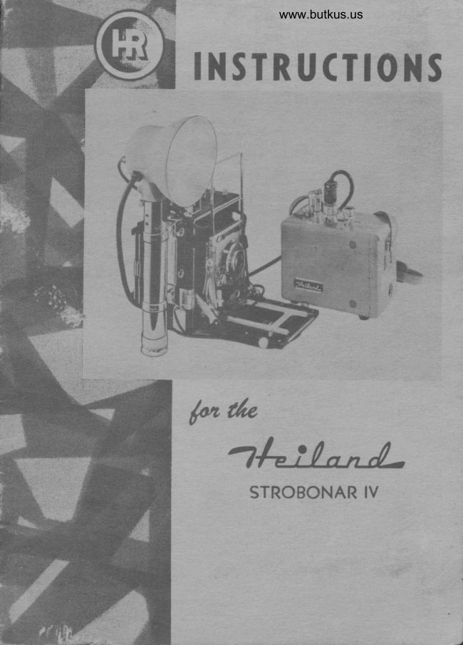
H eiland Strobonar IV User manual
User manual for H eiland Strobonar IV. 19 pages in English. Read the original PDF, download or print a copy without registration.
19 pagesEnglish3.0 MB PDF
Loading your manual…Open PDF directly
Document details
- Brand
- Various brands
- Model / document
- H eiland Strobonar IV
- Document type
- User manual
- Language
- English
- Pages
- 19
- File size
- 3.0 MB
- Category
- Film cameras
- Document date
- Not specified in catalog
Search available document text
Find a term, then jump to its page in the original PDF. Image-only pages may not be searchable; check the PDF for exact wording and diagrams.
Page 5 · Read text
thr:"Uil-   DENvER

           approximates l/1000                         a second, which is fast enough to stop aII action                                    -of           except extremely high'speed devices, such as machinery or aircraft pro-
            pellers,_where special equipment may be required. Due to tt i  o"ry tigt          speed flash, it is dcsirable to use the fastest shutter speed available on
           cameras with between-the-lens shutters. Under conditions of orclinary ,oo-             lighting,                                            - using slorver _sh_utter_ speeds will produce no appreciable difier-
           unce in the amount of light falling on the negative. For ouldoor use under
           sunlight conditions or under strong indoor artificial light, slowe, .h,rt,",
           speeds will increase b-ackground to some extent but wlll not uppr""iubly
            affect the subject included within the range of light furnishe'd' bv thl
           Strobonar. When.photographing fasr actionln daylrtht, the highesi'shut.
            ter speed on the between-the-lens  shutter is desirablJ in order "to prevent
           double images. The                                     temperature of the light produced by th'e- Stro-                                    -color             bon_ar-is approximately 2000' Kelvin, which is viy close to thaioinai,r.al
             daylight.
        DESCRIPTION:
                 -    The Strobonar IV is intended for operation only from 105 to t2s             volts, 60.. cyclest            teries. The Strobonars-AC. orarefromnotitsdesigne_d_forself-containedoperationrechargeable6n otherwetuoliugl.cell b*o. -           Irequencies and MUST NEVER BE coNNr'crnn ro A oc sorjncr.t          O-lly those between-the-lens  shutters having "X"-contacts or provisions for
         "X" selection can be fitted with the Stroboiar IV. This qualification
          most of the current types of shutters, allowing use of thl Stro[onars"ou"r,with
         9ompur                   Shutters on such cameras qs, Rolleiflix, Rolleicord, S;;;-ikonta         B, and Retina so^.equipped, and o'X"-contact itapax, Alpira",'ii"i--u"d          supermatic (X) Shutters. Many of the Ilex Shuti"rr-"rrd current Rupu*
           Shutters have delay selectors which permit a setting of ooX,,; these .t rrtt"r,
        may also be used rvith the Strobonari. Many of the-later model focal piane
            shutters are equipped with contacts permitiing use of Srrobonars uni- tt
         camera manufacturer's recommendations concJrning shutter speeds shoulcl"
         be followed. On older cameras not having "X"-conLcts it is rlcommended
           that such contacts be built-in by a competent repairman. Heiland Factory
            Rep-resentatives can offer you this service througir your authorizecl Heiland
          Dealer. The camera shutter outlet on the Stro'bonar will accepi H"iiu"a
          standard cords and the following are available:
          HEILAND NO. 57  For X-contact Supermatic, Rapax, Alphax, and
                                    similar shutters.
          HEILAND NO. 58  For A.S.A. Flash Shutters with X.contact syn-
                                      chronization.
          HEILAND NO. 60  For Klio or Prontor Shutters with X-contact.
            H.EILAND NO. 6T  For Kine Exacta Camera.
          HEILAND NO. 62  For all cameras equipped with Compur X-contact
                                    synchronization.

t
View original page 5Page 6 · Read text
www.butkus.us
              4-t:!-t-tt-   DENvER


                   www.butkus.us


OPERATION:
   The Control Panel on the top cf the Strobonar IV contains a selector
switch permitting settings of: "CHARGE", used for recharging the bat-
teries of the unit; "OFF"; "IINE", which permits operating the unit from
AC line current as specified under "DESCRIPTION" on page 3; and
"BATTERY", which permits operation of the Strobonar directly from its
own built-in, rechargeable batteries.
    Each working position on the control selector switch is set with a
colored jewel which will glow when the unit is operating or charging.
Proper operating position is thus assured by a quick glance at the control
panel.
    The Strobonar IV is equipped with a safety device which permits opera-
tion oI the unit only when the lamp cable is plugged in, and the extension
outlet is either attached to the extension cable, or the extension outlet cover
is in place. This assures complete safety with absolutely no possibility of
contact with high voltage terminals. The "CHARGE" position may, how-
ever, be used without these cables or cover in place. (No high voltage is
present while the batteries are being charged. ) When the selector switch
is turned to the "OFF" position, the capacitors oI the Strobonar are auto.
matically discharged. The charge which has been built up in the capacitors
while operating on battery may, however, be held for a short time by turn-
ing the selector switch to "LINE" even though the unit is not connected to
an AC outlet. This will permit holding a partial charge in the capacitors
during short waits between shots. The batteries of the Strobonar IV must
be filled and charged before the Strobonar can be operated.
   When putting the Strobonar into service after a relatively long period
of non-use (over l0 days), it is recommended that the neon indicator
(located in the bac'k of the lamp assembly) be allowed to light once while
View original page 6Page 7 · Read text
lht:'(-t-tt-   DENvER

 operating the batteries. After this initial reforming of the capacitors,
 operation may be continued from AC or batteries as desired. Photography
 should not be attempted before the neon indicator is illuminated. fne tife
may then be flashed by pressing the manual discharge switch located on the
 rear of the Strobonar lamp assembly. I{ the unit has been out of service
 for any- appreciable length of time, the charging time may be relatively
 long. This may vary from 30 seconds to several minutes, or possibly longer,
 depending upon the length of time the Strobonar has been- out of ."ru-ic".
 Prior to actual use, the unit should be allowed to reach full charge and
be discharged a number of times until the charging time is on the order
 of B to l0 seconds, which would indicate that forming o{ the electrolytic
condensers has been completed and that the unit is now ready {or normal
 use.
    The manual discharge switch, located on the rear of the Strobonar
lamp assembly, is not used in actual photography except with the shutter
adjusted to "TIME" or "BLJLB" and opened. Except for this case, the
actual flash must always be cause/ by operation of the "X"-contact shutter,
connected to the Strobonar with the appropriate cord.
       _ X-contact operation is accomplished by connecting the proper cord
to the shutter contacts and to the outlet in the back of the lamp assembly.
The shutter is then tripped by the manual release or cable release on
the camera. X-contact shutters which are in good repair will permit use
of the Strobonar IV at all speeds with accurate synchionization.-  It should
be remembered that, due to the instantaneous nature of electronic flash,
exposure is determined by the diaphragm stop and light output selector
rather than by the shutter speed.
     X-contact-Solenoid Operation allows tripping the shutter from the
Heiland 24-3 and, similar battery cases equipped with trigger switches.
Synchronization  is, however, accomplished by the built-in X-contacts; the
solenoid being -used only to trip the shutter. It is also possible by this
method of operation to trip the shutter and the Strobonar from a distance
using the Heiland $-r0 Remote Control Cord. Connections should be
made as outlined above, in addition to a cord from the solenoid to the
"tripper or extension" outlet in the battery case.
      It is possible to utilize one or more additional Strobonars as extension
units by use of either the Heiland Fotoeyes or a cube tap and connecting
cord {rorn the shutter to the shutter contact outlets in both Strobonars.
The latter method is not recommended for certain shutters as the shutter
contacts must carry an additional load with each additional unit. The
                 are considered                                     satisfactory                                                 operating                                            for                                                two                                                      or more{ollowing shutters                      *X",Strobonars:            Supermatic                       Rapax                                         ooX", Alphax                                                                and                                                              Prontor,                                                          Klio,                                             "X",
Compur. If in doubt about a particular shutter {or this appiication, please
write direct to Heiland Research  . Corporation, r30 Easr Fifth Avenueo
Denver 9, Colorado.
   When using the Fotoeygs, as described on page 13 only the current

                                                                              /
View original page 7Page 8 · Read text
www.butkus.us
               4zi^|srA-   DENvER

       from the prirnary Strobonar is passed through the shutter contacts and
        as many units as desired may be used with no harm to the contacts.

      CAUTION:
           .  The Unitized Chassis of the Strobonar IV should never be removed
       as the unit stores dangerous amounts of energy in the voltage range of
       1000 volts, and direct contact with this stored energy could be lethal. The
        unit is equipped with a safety switch so that removal of the chassis will
        short circuit the energy-storage capacitors and open all operating circuits,
        but it is recommended that the chassis be removed only by Heiland dealers
       or their service personnel. When the chassis has been removed, the unit
        cannot be operated unless the safety switch is blocked.
         The Strobonar should never be operated in atmosphere containing
        explosive dust or vapors as flash tube operation may be accompanied by
        sparking at switches or socket contacts, and serious consequences could
         result from such operation.

      LIGHT CONTROL:
          Due to the extremely high light output of the Strobonar IV, a variable
        output control has been incorporated into the control panel. Light output
      can thus be regulated from 50Vo to I00% of the maximum with inter-
       mediate settings calibrated in 5% gradations. Close-ups and/or wide
        aperture shots are thus possible without the necessity of difiusers which
       might be undesirable for certain types of work. All guide numbers listed
         in this manual are for I00% of the available light output. When the selector
         is set at 50Vo the guide number must be multiplied by a {actor of .7 or
           |  "I)' stop wider aperture used; when set at 75/6 the factor will be .87
        or L/z "{" stop wider aperture.

      GUIDE NUMBERS AND LIGHT CHARACTERISTICS
         The Heiland Strobonar IV produces more efiective light than any
        other portable electronic flash unit ever designed. The distribution of the
         Iight is extremely even over the area included by normal focal length lenses.
         The Strobonar is used much like conventional flash except that ex-
        posure time is determined by the duration of the flash (1/1000 of a second)
        rather than by the shutter speed. Exposure is, therefore, controlled by
        the diaphragm setting on the camera and by the variable output selector
      on the Strobonar.
           Extended development is recommended for most films exposed with
         electronic flash, not to increase guide numbers, though this is a result, but
        rather to increase contrast and detail in the negative. Highlights do not
        block up and no excessive grain will result from this procedure with most
        films and the manufacturers' recommendations should normally be fol-

L.*
View original page 8Page 9 · Read text
lh-iltt4-    DENvER

  lowed. Eastman Kodak suggests the use of its DK-60a developer for its
  films and Ansco suggests the use of its Permadol developer. These two
  developers do not give excessive grain or contrast when used with the
  Strobonar.
     The Strobonar IV at last makes possible action color at reasonable
  distances. Its amazing light output combined with the even illumination
 and the favorable color temperature of the Strobonar make the Strobo-
  nar IV the ideal unit for almost all types of color work. The color tem-
  perature of the light emitted by the Strobonar (About 7000" Kelvin) is
  very close to that of daylight and daylight type color film may be used
 with no color correction necessary. Some photographers prefer slightly
 warmer tones than those produced by the Strobonar in which case a filter
 such as the 81 C, or that recommended by the manufacturer, may be of
  value.


     Listed below are suggested guide numbers for the Strobonar IV under
the average conditions described above.
    50Vo over--or extended-development '(LL/z X the development recom-
mended by the film manufacturer) is recommended for the reasons discussed
under "DEVELOPMENT". This extended development, for the purpose oI
gaining contrast, results in a slightly higher guide number. Most fine-grain
developers cause a definite loss of film speed. For this reason, guide num-
bers are shown (for black and white films) for "Fine-Grain," "Normal"
and "Extended" Development.

            (See following page lor suggested guide numbers.)


                                                       I
View original page 9Page 10 · Read text
www.butkus.us
                   -h-I-t/-     osNvER

                   SUGGESTED GUIDE NUMBERS
                          Brecr exn WHrrr Frlus
                                                   "Fine-Grain"   "Normal"   "Extended,"
          Ansco Plenachrome and Supreme...... 200         280         340
                 Superpan Press               ...... 280         400         490
             Isopan                             ...- 225        320        390
          DuPont H.S.P. 428                  340         500         610
                    Superior                     400         560         680
         Kodak Verichrom" ;;J Pl;; i...........  200         280         340
                 Super XX ...-..--...              280         400         490
                 Super Panchro Press "8".-.---.- 315         450         550
                 Royal Pan                    400         560         680
            Polaroid Type 41...                               200
                           Dlvlrcnr Coron FIrus
           Ektachrome and Kodachrome...--.-..-...-   80-90

           Using the guide numbers given above, the approximate  oof" stop setting
        is found by dividing the guide nurnber by the distance in feet between
       the Strobonar lamp and the subject. For example, using Isopan cut film
      and development A, at a distance of 30 feet between camera and subject
       with a guide number of 450 the "f" stop would be 15; the nearest marked
        "f" stop to this would l:e f./I6. When working outdoors with no reflecting
       backgrounds, the guide numher is lower than those given above. Conversely,
       working indoors with light-colored or white walls as reflecting backgrounds,
       the guide numbers will be higher than those given above. In general,
       there is more latitude in choice of guide numbers for black and white
        film than for color film where light values are more critical. To determine
      a personal exposure guide number, select a subject 20 {eet away in a mod-
        erately sized room. Make one negative at each of the following aperatures:
        I/8, II, 16, 22, and 32. Develop all of these negatives under carefully
        controlled conditions and select the best one. If the best one was taken
       at I/22, the guide number is 20x22, or 440. The same system is used for
        color except that the test photographs are made at a distance of 10 feet,
      and aperatures of I/4, 5.6,8, II, and 16 are used.


\
View original page 10Page 12 · Read text
www.butkus.us
                   4=t:,(-tA-   DENYER

       BATTERIES
           The Strobonar IV is supplied with two Willard ER-11-2 Storage Bat-
            teries which are shipped dry and must be filled and given an initial charge
         before using. In the dry condition the batteries will keep several years
         without deteriorating. Therefore, if you do not intend using your Stro-
        bonar immediately, do not fill and charge the batteries. The batteries
          must, however, be filled and charged before the Strobonar can be operated
           either on "LINE" or "BATTERY."
             Raise the spring clip and slide the battery compartment door away
        from the Strobonar. Remove and discard the portions of tape covering
         the vents on the batteries. Unscrew the small red filler cap on the top
          of each battery (a coin will serve as a screwdriver) and fill each battery
         to the bottom of the float channel visible through the windows on the
           side of the Strobonar. It is recommended that the batteries be removed for
            this initial filling; see note on page ll  for removal of batteries. After filling,
          coat terminals with vaseline to prevent corrosion. Let the batteries stand
           Ior 4 to I0 hours so that the acid can soak into the dry plates and lining,
          then add more acid if the liquid level has dropped below the bottom of the
          channel. After the initial filling and 24-hour charge, all lurther additions
          to bring the liquid level up are made only with distilled 'water. Do not use
           city tap water as it may contain chemicals which will harm the batteries.
        The distilled water may be purchased in any drug store or battery station.
            The battery condition is indicated by a colored charge indicator visible
          in the float channel of each battery. This channel may be partially filled
         with acid by tipping down the battery end of the Strobonar. The battery
         charge may then be read by noting whether or not the indicator floats.
        The indicator will float if the battery charge is above approximately 50/o
         and charging of the batteries should continue approximately 4 hours a{ter
          the indicator begins to float. It is not necessary or desirable to allow the
           battery to become {ully discharged before recharging.  It may be recharged
           at any time that a discharged condition is shown by the red charge indicator.
       To recharge, use the 12 {oot cord supplied with the Strobonar IV connect-
         ing it to the recessed outlet on the left side of the Strobonar and to an
           outlet supplying 105 to 125 volts 50 to 60 cycle AC. A{ter these connec-
          tions have been made, the switch should be moved to the "CHARGE"
           position. The amber jewel opposite the "CHARGE" position will then glow
          indicating that current is reaching the charging circuit of the Strobonar.
             Charging time will vary, but generally, a fully discharged battery may
        be completely recharged overnight. When a battery is completely dead
          or the supply line voltage is below 115 volts, the recharging time may be
        more than 12 hours. Charging may be safely continued for several hours
           after the red indicator is floating I horvever persistent overcharging will
          eventually damage the batteries. Normally batteries should be charged
            lor 4 hours after the indicator rises.
                                                10
\
View original page 12Page 13 · Read text
4=-:'b-A-  oENvER

   Make certain the red battery lead is attached to the "positive" termi-
nal of the right hand battery and the black lead t,r the "negative" terminal
of the other battery. The jump lead should then connect the remaining
positive and negative tertninals. Improper connection of battery terminals
while charging will result in damage to the batteries.
   The hydrogen gas generated while charging batteries is explosive. Do
not bring open flame near batteries while being charged. Do not tamper
with connections while the battery is being charged; this could produce a
spark which would ignite the escaping hydrogen.
   NOTE: If it is necessary to remove the batteries for cleaning, replacing
or checking, this may be accomplished by lo.rsening the two captive screws
located on each side of the left end of the Strobonar capacitor case near the
battery compartment door. The end cover of the Strobonar may then be re-
moved by sliding the top of the cover away from the Strobonar, then sliding
the cover downward, away from the two Iocating pins present on the under
side of the Strobonar.
   The cover is replaced by reversing the process. It  is recommended
that the line cord be removed and the unit turned to "OFF" before remov-
ing the end cover. No danger is involved in removing this cover and no
high voltage leads or terminals are exposed. The unitized chassis of the
Strobonar which is now partially visible should not, hou;eaer, be rernoued.


                         www.butkus.us


                                                      ll
View original page 13Page 14 · Read text
www.butkus.us
                 4-J:-b'A-   oENvER

      MOUNTING THE LAMP ASSEMBLY
          The lamp assembly of the Heiland Strobonar IV is designed to be
        mounted on standard llz" battery cases or the Heiland Model HR-9 Mount-
         ing Tube. The battery case or mounting tube may be attached to the camera
         with any of the listed I-Ieiland mounting brackets. These provide a sturdy,
         dependable support which allows carrying the camera by the battery case
        and also affords easy, quick removal for ofi-the-camera flash. The Heiland
         24-3 Battery Case, 25-2 Battery Case, and Heiland HR-9 Mounting Tube
        are equipped with tripod sockets to permit mounting the lamp assembly
        on the Heiland Fotoclamp or on standard tripod heads.

      REFLECTOR i\IOUNTING COMBINATIOIIS
           The Strobonar IV Lamp Assembly may be mounted with the Heiland
        24-3 Battery Case or Model HR-9 Reflector Mounting Tube and any of
         the following combinations:

             Heavy Duty
            Mounting Bracket                                  Camera
                70..-...----..--           Anniversary Speed Graphic, all sizes
                            77......--.. "'....................:..::....... . Meridian, 2lafilf Busch, n t  I
                               3m;3;::'.tH;fftl$    72                   74..-...--..--..            For Flat Mounting
                   75.......-.-...-            Crown-Speed Craphic o'34"
                   76.......".-....            Crown-Speed Graphic 0045"
          The 24-3 Battery Case, 25-2 Battery Case or Model HR-9 Mounting
       Tube may also be equipped rvith the Heiland 4373 Model E Clamp and
        mounted in the following combinations:

                  Bracket                                       Camera
                  R-7.-.--...-...              Universal Reflex
                R-7A-.....--.               Universal Reflex Heavy Duty
                  M-II.-.-..-..-            Kodak Medalist II
                  235.-..-......-           Kodak 35
                   B-I--....--...-               Zeiss Super Ikonta B
                  135...-.-......       --.-......--....-Kine Exacta
                 335.....-.-.---              Retina I, Retina II, and Leica
                 220----.-..-...      .-.-..-....-....-Kodak Tourist
                  320....--......              Polaroid Land
                Standard Camera Bracket....---.For most miniature and roll film
                                            cameras
                4450 Clip.              .....1-.-..-...--.For flat, direct mounting on cam-
                                               eras or special brackets
                                               12

h
View original page 14Page 15 · Read text
-l=-I-tA-   oENvER


                                                                 \         /srnoaoun                                                 \/IE

             INSTRUCTIONS
                            for use and operation o{
   FOTOEYE, MODEL HR.ll PHOTOELECTRIC TRIPPER FOR
                  STROBONAR IV
   The Heiland Fotoeye, Model HR-fl is designed to flash the Strobonar
IV as a slave unit when light of sufficient intensity falls on the photoelectric
surface of the tube. There is no decrease in light output of either unit
when using the Fotoeye. The Fotoeye will flash a Strobonar repeatedly
without the conventional necessity of replacing flash bulbs or making any
adjustments.-   The Fotoeye cable connector is plugged into the indicated outlet on
the top of the Strobonar and is polarized automatically by 1!e plug or theFotoeye may be plugged into the shutter outlet if Model HR-llA is used.
The placement of the Strobonar is a matter of choice for lighting efiects
desired and the Fotoeye may be mounted in any position which will receive
sufficient light from the master source to activate the slave unit. A cord
permits mounting the Fotoeye in the beam o{ t}re master unit-while placing
ih" l"*p of the ilave unit elsewhere. A tripod socket in the Fotoeye {acili-
tates convenient mounting on a standard tripod head or with the Heiland
Fotoclamp. The Fotoeye will trigger the Strobonar by direct or indirect
light of Jufficient intensity and the shield should be rotated allowing the
miximum amount of light from the master source to enter the window in
the shield. The master flash may be any unit that produces sufficient illumi-
nation to fire the Strobonar by the Fotoeye: a Strobonar or conventional
flash bulb may thus be used as a master source. A Strobonar IV will trigger
the slave at 60 feet and may be used in any reasonable lighting arrange'
ment; an example being shown in the figure on this page.
                                     I3
View original page 15Page 16 · Read text
www.butkus.us
                 -il=tihtA-   oENvER

          The room reflectivity affects distance and placements; therefore,-the
         best means of determining if the slave is functioning properly is to flash
         the master source without attempting to expose the film.
                 It is necessary to allow the Strobonar with attached Fotoeye to charge       20 seconds after the neon indicator shows that the Strobonar is fully
         charged. This additional time is required to charge a condenser that is in
         the Fotoeye. The Strobonar may be operated from lI5 volts AC or from
         the batterles which are incorporated into the unit. The master unit is the
         only unit that is necessary to be fired directly by the camera shutter as
         the slaves are fired from the light of the master'
           The operating precautions that should be observed are as follows: If
          the tube of the Fotoeye is removed from its socket, the tube, when replaced,
         should be seated completely. The tube shield with the tube properly seated
         should be capable only of being rotated; the Fotoeye will usually fire the
         Strobonar if the glass envelope of the tube is touched by hand through
         the window. The Fotoeye will also fire the Strobonar if the Strobonar is
          {ully- charged when the Fotoeye is inserted into the shutter contact outlet.
          The light patrern provided by the Strobonars may be determined by
          direct addition of the values at all points of same physical position as shown
         in the Strobonar instruction manual, page 9. Test shots with different "f"
          stops may be necessary to determine proper exposure in initial stages of use.              -           The delay of the Fotoeye is only a few millionths of a second; there-
          fore, photographically it can be considered negligihle.
           The Heiland Strobonar I with the Model HR-7 Fotoeye provides a well
         balanced sidelighting unit for use with the Strobonar IV. Again, there is
        an increase in total light output from each additional unit.
      STROBONAR IV EXTENSION NIODEL HR-T8
           The Model HR-18 extension lamp provides a very convenient fill in or
          sidelighting unit for the Strobonar IV. It is equipped with a 20' cable and
       a removable tube with tripod socket which has been incorporated into the
         base, permitting mounting on standard tripod heads or on the Heiland
        Fotoclamp. The extension lamp may be mounted on a Heiland 24'3 Battery
        Case or similar unit.
          The extension outlet of the Strobonar is covered with a safety cap
        which is lifted straight up to remove. The Strobonar cannot be operated
          unless either the safety cap or the extension plug is in place. This assures
         absolute sa{ety since no high voltage terminal is at any time exposed.
               Identical controls are present on both the camera lamp and the exten'
          sion lamp in order that the Strobonar may be operated from either lamp.
        The time required for the neon indicator on the extension to glow may_vary
          slightly from the indicator on the camera lamp but the difierence will be
        so slight that it may be ignored. The light output of the Strobonar is
           dividecl between the two lamps when using the extension and the guide
        numbers used should be changed accordingly.
                                              t4                                                                                                                                                                          I

b.
View original page 16Page 18 · Read text
www.butkus.us
                   d--:!-t4-    DENYER


                         WARRANTY
             All units of the Heiland Strobonar series are unconditionally guar-
         anteed against defects in material, workmanship, or operation for a period
          of 90 days from date of sale by authorized Heiland dealer to original pur-
         chaser. The guarantee covers the General Electric Flash Tube and the
         Willard Batteries as well as the units themselves. The Heiland Research
          Corporation reserves the right to make such changes, modifications. or
         improvements as it may from time to time deem advisable without liability
          to purchasers of models not incorporating such changes, modificationS, or
          improvements.
             Like all Heiland equipment, Strobonar units are earefully inspected,
            quality-built, and pre'cision tested to insure years of unfailing performance.
         Should any part of your Strobonar equipment  fail to operate to your satis-
           faction, it should be returned only to an authorized Heiland dealer for
           service. If necessary to return the units to the Heiland factory while under
          warranty, it should be returned only through such authorized dealer and
         not directly to the factory. Many Heiland authorized dealers are fully
         equipped to service these instruments at moderate prices after warranty
        has expired. They have been supplied with complete circuit information
        and all other data necessary to give you fast and dependable service.
              All inquiries or correspondence regarding Heiland Strobonars should
         mention both the model number and the serial number and be addressed
            to:
                      HEILAND RESEARCH CORPORATION
                             130 East Fifth Avenue                                                                                    ,                              Denver 9, Colorado                               tr

         NOTE: Heiland Strobonars are fully licensed under the patents of
          Edgerton, Germeshausen, and Grier, and are equipped with General Electric
           flashtubes.


                                        Copyright-l952 Heiland                                                    ,Ftr                                                                    Ft


                                            t6
\                                                                Form 1?38-l
View original page 18Page 19 · Read text
STROBONAR IV


HEILAND RESEARCH CORPORATION
           I3O CAST FIFTI{ AVENUE
            DENVER 9. GOLORADO
View original page 19Related documents and language editions


From the M. Butkus archive. Original publisher and archive notices are retained.
Check the model and edition against your equipment.
PDF verified 2026-10-10.