Film cameras
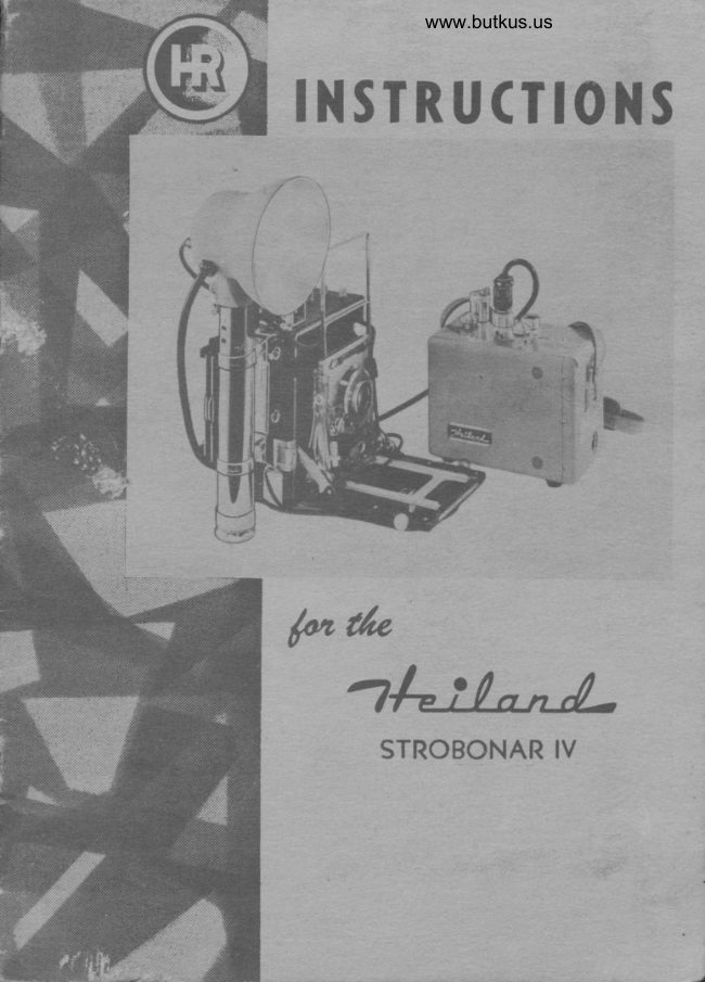
Heiland Strobonar I, I-A, III User manual
User manual for Heiland Strobonar I, I-A, III. 26 pages in English. Read the original PDF, download or print a copy without registration.
26 pagesEnglish2.3 MB PDF

Loading your manual…Open PDF directly
Document details
- Brand
- Heiland
- Model / document
- Heiland Strobonar I, I-A, III
- Document type
- User manual
- Language
- English
- Pages
- 26
- File size
- 2.3 MB
- Category
- Film cameras
- Document date
- Not specified in catalog
Search available document text
Find a term, then jump to its page in the original PDF. Image-only pages may not be searchable; check the PDF for exact wording and diagrams.
Page 4 · Read text
l W           D E N . E R


INSTRUCTIONSFOR USE OF HEILAND STROBONART" IA AND III


                                      STROBONARI-A
                                                          (with Model HR-9
STROBONAR  lll Complete                            Mounting Tube)


 STROBONAR  l, Complete
     (with Press Brocket)


INTRODUCTION:
    The  Heiland  Strobonar    I,  Strobonar  IA  and  Strobonar   III  are  elec-
tronic  repeating  flash units designed  for use with  between-the-lens shutters
having  "X-contacts".   They  utilize  a Xenon-filled  flash tube made  by  the
General  Electric  Company  and  designated  as the  FT-I10.   In  comparison
to  conventional  flash photography,  the  electronic  repeating  flash  delivers
a very intense  light  of exceedingly  brief  duration.  The  flash duration  ap-
proximates     | / 2000  of  a second, which   is  fast enough  to  stop  all  action
except photographing  extremely  high-speed  devices, such as machinery  or
aircraft  propellers,  where  special equipment may be required.  Due  to  this
very high speed flash,  it  is desirable  to use the  fastest shutter speed avail-
able on cameras with  between-the-lens  shutters.  Under  conditions  of  ordi-
nary room  lighting,  using slower shutter speeds will  produce no appreciable
difference  in  the amount  of  light  falling  on the negative.  For  outdoor  use
under  sunlight  conditions  or  under  strong  indoor   artificial   light,  slower
shutter speeds will  increase background  to some extent but  will  not appreci-
ably  affect the subject included  within  the range  of  light  furnished  by  the
Strobonar.  When photographing   fast action  in  daylight,  the highest  shutter
speed on the between-the-lens shutter  is desirable  in order  to prevent double
images.  The  color temperature  of the  light  produced  by  the Strobonar   is
approximately  7000 " Kelvin,, which  is very close to that  of natural  sunlight.
View original page 4Page 5 · Read text
4=i-!--/-     DENvER


       DESCRIPTION:
           The Strobonar f, IA, and III  are intended for qperation only from 105
          to 125 volts, 50 to 60 cycles AC, or direct Irom the Heiland Strobonar Power
        Pack. The Strobonars are not suitable for operation on other voltages or
         frequencies and MUST NEVER BE CONNECTED TO A DC SOURCE.                                                     ooX-contact"        Only those between-the-lens shutters having               or provisions lor
         "X"  selection can be fitted with' the Strobonar  I  series. This  qualification
        covers most of the current types of shutters, allowing the Strobonar to be
        used with Corhpur Shutters, on such cameras as Rolleiflex, Rolleicord, Super
         Ikonta B, and Retina so equipped, and "X'contact" Rapax, Alphax,  Ilex,
       and Supermatic (X)  Shutters. Many  of  the  Ilex  Shutters and current
       Rapax Shott".s have delay selectors which permit a setting of "X":  these                                                                 'oX"         shutters may also be used with the Strobonar in the      position. Many
          of the later model miniature cameras with local plane shutters are equipped
         with  built-in  contacts to  allow use of  electronic  flash units such as the
        Heiland Strobonars. When using focal plane shutters the camera manu'
         factureros recommendations concerning shutter speeds should be followed.                                       'oX"-contacts      On older cameras not having               or synchronized shutters, it  is                           ooX'o-contacts       recommended that             be installed by a competent repairman.
        Authorized Heiland representativescan ofier you this serviee through your
         dealer. The camera shutter outlet on the Strobonar will  accept Heiland
        standard cords, and the following connecting cords are available.
          HEILAND NO. 5?  For  X-contact Supermatic, Rapax, Alphax,  and
                                     similar  shutters.
          HEILAND NO. 58  For A.S.A. Flash Shutters with X-contact sychro-
                                     nization.
          HEILAND NO. 60  For Klio or Prontor Shutters with X'contact.
          HEILAND  NO. 6f   For Kine Exacta Camera.
          HEILAND NO. 62  For  all cameras equipped with Compur X'contact
                                   synchronization.

       OPERATION:
           To place the Strobonar Model HR-3, HR-3A, or HR'12 in use the short
        connecting cord attached to the instrument should be connected to the
          l2-foot exiension cord supplied as standard equipment. This in turn, should
        be connected to a house culrent  outlet supplying proper voltage and fre-
        quency as specified above. The "ON-OFF"  switch (when using the Stro-                                     66ON"        bonar I)  should now be placed in the        position and after a short time
          interval the small neon indicator will  give an orange glow, indicating that
          the energy storage is  sufficient to cause a flash. The Strobonar IA  and
         Strobonar III  are not supplied with a switch since they are usually used
          with  the Strobonar Power Pack.  Photography  should not be attempted
                                 3
b                              www.orphancameras.com
               . ,  " €
View original page 5Page 6 · Read text
-l=t:-/-t/-      oENvER                                                    .\.t\_


         before the neon indicator  is illuminated.  The tube may now be flashed by
         pressing the manual discharge switch located on the rear of the Strobonar
                I or IA case or on the reflector assembly of the Strobonar  III.    If  the unit -)
        has been out of service for any appreciable length of time,  it  is advisable  (
          to charge the capacitors of the A.C. light  unit lrom  the Strobonar Power   (
       Pack  (if available) before connecting to qn A.C. outlet.  After  this initialJ
        charge the unit may be operated from A.C. or from the Strobonar power
       Pack as desired. Prior to actual use, the unit should be allowed to reach
             full  charge and be discharged a number  of  times. When the X-Contact
         shutter has been connected to the outlet with the proper Heiland cord, the
          unit is now ready for photographic use and flash operation will be controlled
        by the shutter contacts.
           The manual discharge switch is not used in actual photography except
         with the shutter adjusted to "TIME"   or "BIJLB"  and op"tr"d.  bxtept  for
          this case, the actual flash must always be caused by operaiion of the shutter.

       CAUTION:
           The rear cover plate of the Strobonar capacitor case should never be
       removed as the unit sto_resdangerous amounts of energy in  the voltage
         Ialgg  oJ 1000 volts, and direct  contact with  this stored energy could  f,e
           exprostv_eduqt*9,1*ygpggq.,.a,sflash-1ub.popeqatffirrded        ing       by sparking at switchesor socket contacts,and seriousconsequences                                                                                                                                                                                                                                                                                                                                                                                                                                        " ' . . : J . ' , | i t corifii l          result from such operatiol.'
           The unit  is equipped with a safety switch so that removal o{ the rear
        cover will short circuit the energy-storagecapacitors, but  it is recommended
         that  this rear cover be removed only by Heiland  dealers or  their  service
        personnel. When the rear cover has been removed, the  unit  cannot be
        o-peratedunless the safety switch is blocked.  Failure  to do so will damage
         the unit.
     GUIDENUMBERS:
               \' I   Heiland Strobonars are used much like conventional flash except-by that
        exposure is determined by the duration  of  the  flash rather  than     the
         shutter speed, and over development is not only possible but  in many in-
        stances is desirable.
           The f_ollowing guide numbers were determined under exacting condi-
         tions, the light output of the Strobonars used being an average of 100 con-
        sec_utiveunits produced.  All  black-and-white films were processed at 69"
        Fahrenheit  in a tank  with  intermittent  agitation  using the  {ollowing  de-
        velopers:
               Development A-Ansco   films, 5 minutes in Ansco Permadol          *l
                               Defender 428, 6 minutes in Defender l6D
                            Kodak films, 6 minutes in Kodak DK-60a
                                         4                                                                                        / 1

\  ,-:=
View original page 6Page 8 · Read text
-l--I-tA-     oENVER


    RECOI\4MENDEDGUIDE NUMBERS FOR STROBONARIII
                           (Continued)
                                                Develop-  Develop-  Develop-
                                            ment A    ment B    ment C
 Pecr Fnu
                                                                                                                              IF                                                  t     Ansco Supreme                    270    350
                                                                                                                              tF     Ansco Superpan Press-.-------          270    360
    Kodak Plus X.----..                  270    350       *
                                                                                                                              IF                                                           I    Kodak Super XX.                   270    360                                                                                                                                                         a
 Roll  Fllu
    Ansco Superpan Press...-....-           360     480            'T                                                                                                       II
    Ansco Supreme                     270    360         :*                                                                                                                                                                                                         :tt                          i .    Ansco Plenachrome ---.__.--.           270     420
    Kodak Super XX.-..-....,..            340    510            .r                                                                                                       I
  -   Kodak Plus X.----                    320     460       *
     Verichrome  - -                       270     420       *
 Coron Frlu
    Kodachrome Daylight              ._......::....., 45
    Ektachrome Daylight "..-.......-..         40
                                      40
                                      45
 * Not recommendedbv Heiland.
           the guide-lumbers given above, the approximate  "f',  stop set-  .    IJri"g
 ting is found by dividing the guide number by the-distance in feet beiween
the Strobonar larnp and the subject. For example, using Isopan cut film
and normal development,at a distance of l0 feef betwe"r,       and sub-
ject-with a guide number of 180, lhe o'f" stop would be "a-bralB:  the nearest
marked "t"  ._,upto this would be f/I6.  When working outdoors with  .ro
reflecting backgrounds, the guide number is lower than-those given above.
Inversely, working  indoors with  light-colored  or white walls   i.   refl"ctittg
backgrounds, the guide numbers will  be higher than those given above.
In general, there is more latitude  in choice of guide numbeis  for black
and white' film than for color film, where more hlht   is required, and light
values are more critical. To determine a p"r.o.r"I          guide numbero
selecta subject-10 feet away in a moderately sized roo-."*po.urlMaki one negative
at each of the following apertures: I/5.6, B, tt,  16,22, and 32. DevelJp all
of these negatives under carefully controlled conditions and select the best
one.  If  the best one was taken at  I/L6,  the guide exposure number  is
l0 x 16 or 160.
    The same system is usecl for color except that the test photographs are      ,
made at a distance of 5  feet" and apertuies of  I/4,  s.6, B,  li,  and 16
are used.
View original page 8Page 10 · Read text
-l=t:-!-t4-     oENvER                                    ,.\


           Because o{ the very high  color temperature of the Strobonar,  it  is
         frequently desirable to overdevelop the negatives. This does not merely
         increase the guide number of the Strobonar;  it actually gives better grada-
          tion and contrast to your negatives. Some types of  film are not recom-
       mended for this overdevelopment,and the film manufacturer's specifications
,        should be followed. The light from the Strobonar closely appioaches that
          of daylight and either panchromatic or orthochromatic films may be used.
        Eastman Kodak suggests the use of its DK-60a developer for its'films with
         electronic flash, and Ansco suggests the use of  its Permadol developer.
        These two developers do not give excessive grain or contrast when used
   .       with the Strobonar.
             For greater depth of field in photographing still subjects, the shutter
         g,ay be opened on "Time" and as many flashes as desired may be used.
       The manual switch on the Strobonar is used for this purpose. I{ the normal
        exposure for the first flash is f/8, with two flashes use f/11, with three or
          four flashes use f/16, and with five to eight flashes use f./22.
:r'"'$:'-                      It  is possible to use one or more additional Strobonars as extension
          units by use of either the HR-7 Fotoeye or by use of a cube tap and eon-
         necting cord {rom the shutter to the shutter contact outlets in both Stro-
         bonars. The latter method is not recommended for certain shutters as the
         shutter contacts must carry an additional load with each additional unit.
      When connecting Strobonars in this manner be certain to observe polaritj'
'        ,on  all cords entering the cube tap from the Strobonars. The  {ollowing
         shutters are considered satis{actory for operating two or more Strobonarsl
        Supermatic "X", Rapax "X", Alphax "X",  Klio, Prontor, and Compur.  If
           in doubt about a particular shutter for this application, please write direct
          to Heiland Research Corporation, I30 East Fiith Avenue, Denver 9, Colo-
         rado.
         When using the HR-7 Fotoeye, as described on page 22, only the cur-
         rent from the primary Strobonar is passed through the shutter contacts and
        as many units as desired may be used with no harm to the contacts.
          When you desire td take the Strobonar out of service disconnect the                                                     '.OFF"        Strobonar or turn the "ON-OFF" switch to the         position (this switch
           is present only on the Strobonar  I ) . When operating from the Strobonar
         Poi.verPack, the switch on the Power Pack may be used exclusively.
                                                                                                                                                                                          i
              MOUNTING THE STROBONAR   I MODEL HR.3                                                  .
           The Strobonar  I Model HR-3 may be mounted on either. side of the            .
       camera with  the reversihle, Universal Camera Platform  Bracket or may           ,{
       be mounted on Press Cameras with the Strobonar  I Press Bracket.  It  is'
         also possible to reverse the serial number plate and carrying strap to  fit
        your particular camera simply by removing the two screws which hold the                                                                                                                                                                        lI         plates on each side of the HR-3 capacitor case.
                                                                                                                                                                                                                                                                                                                                               I
                                                                  I


                                                                                                                                                                       d
View original page 10Page 11 · Read text
1 W             o E N y E R


   THE HEILAND STROBONARI FOLDING PRESSBRACKET
    The Heiland  Strobonar   I  Folding  Bracket  is designed to  facilitate  the
use of the Strobonar Model HR-3 on your Press camera. The Folding  Press
Bracket  is ruggedly  constructed and  will  provide  a very  rigid  mounting
for the Strobonar  HR-3.    It  is easily installed and operated.  The Strobonar
HR-3 can be locked  in  either  of two  positions, on top  of the camera or on
the side where   it  will  be out  of the  line  of  sight  of the wire  frame  finder.
An  easily operated catch  is provided  which  automatically  locks the bracket
on the side or top as desired.


                        www.orphancameras.com
View original page 11Page 12 · Read text
4=t:'(-.r1-    DENvER


  ,              INSTALLATION  INSTRTICTIONS

I. LOCATING MOUNTING SCREW HOLES
    Re{er to the chart and sketches on page 12. The Strobonar  I Bracket
should be located on top of the camera body on the right side as you face the
lens. The mounting holes may be laid out from the dimensions given in
the chart and sketch. The location of the three holes to each other should
be checked. .Use the base of the bracket as a template.

2. DRILLING MOUNTING SCREW HOLES
      Drill three holes through the body of the camera with a *   ot No. 27
drill  being careful not to  drill  through so far as to damage the camera
bellows.

                    THUMBNUT
                        STROBONAR
                           BRACKE T
   NUT
                        CAMERA BODY

WASHER
                    MOUNTING SCREW

  MOUNTINGSCREWASSEMBLY


3. SEMI.PERMANENT  INSTALLATION
        If the Strobonar I Bracket will be frequently removed Irom the camera,
install the mounting screw washers and nuts as shown in the sketch labeledo'Mounting          Screw Assembly.


                         10
View original page 12Page 13 · Read text
l W                            , E N Y E R


    4. PERMANENT INSTALLATION
               If  the  bracket   is  to be  permanently  attached  to  the  camera  install
    screIMS,etc. as above except  that  the washer and hex  nut  shown between
    the bracket and camera body should be placed on top  of the Press Bracket.
    The Press Bracket  will  then  rest directly  on the camera body.  Tighten  the
    nuts securely.
    5. ATTACHINC BRACKET TO CAMERA
       The bracket base may now be placed over the mounting screws and
    fastened with the thumb nuts provided. Tighten securely.
    6. ATTACHING STROBONAR  I TO BRACKET
       With the Press Bracket in  its side or open position f asten your Stro-
   bonar I Model HR-3 in place by means of the two camera type screws in
    the upper leaf of the bracket.
Ia4i7-  7' OPERATION
       The position of the HR-3 Strobonar may be shifted as desired from
    side to top or vice versa by releasing the knurled catch button on the back
    of the bracket. The catch will  automaticallv lock  itself in either side or
    top position.
   Note:
      Many cameras not listed in the chalt on page 12 also may be easily
     fitted with the Folding Press Bracket. Use the bracket base as a template
                                        l1
                           www.orphancameras.com
View original page 13Page 14 · Read text
th-:-trt-A-   DENvER


and from  it mark three holes as widely spaced as possible on the right side
oI the top of the camera as you face the lens. Make certain that the screw
head and washer when in piace will  not interfere with any part inside of
the camera. Steps 2 thra ? should then be followed  to complete the  in-
stallation.
                                                 I
                                                 I


                                                              f2 z DRIL L

           C A M E R A   A B c D   N OTE
                 4 I 5  S P E E D G R A P H I C          r-Lr e
                                                                                                                                                                                                                                                                                                                                                                           l   l         '^tjllf;               4 , ( 5 A N N .G R A P H I C                   tl.'i{t{{HE?E'
              ZA x 3.1 CR'N.GRAPHlC   r"?.      t ;
                  2 * X 3 I A N N GRA P HIC   rr iCe  9           O F C A I ' € R A
               4 r 5 LINHOFTECH.Itr        a        4
               4 x 5 B U S C H              t *                ltlt
               2 f x 3 l B U S C H                     I          r l
               4 x 5  B . a  J .                                        I

    STROBONAR POWER PACK-MODELS   HR.4A AND HR.4B
INTRODUCTION:
    The Strobonar Power Pack Model HR-4A  is designed for use with
the Heiland Strobonar  I and I-A and the Strobonar Power Pack Model
HR-48 is designed for use with the Heiland Strobonar III.  fn some special
cases where an extra fast charging time is required, the Power Pack Model
                                            *"*'11ffi'""i":;il.iJil:Jl:f#Hn'*:'"'t;,"'"""rr orr.Ainuboot
15 to 20 seconds. The Model HR-48 Power Pack  will  charge the Stro'
bonar III  in about 8 to l0 seconds. The Power Pack operates as an inverter,
changing 4 volts D.C. to the equivalent of 115 volts A.C. The Model HR-44
provides a maximum power output of 5 volt amperes and the Model HR-48
about  l0  volt amperes. While  these inverters  will  operate some small
appliances, they should not be used with any device consuming more than
5 or l0 watts respectively and are not suitable for use with  electric clocks.
                                t2
View original page 14Page 15 · Read text
l W           D E N . E R


BATTERIES:
    The Strobonar Power Pack  is supplied with  two  Willard  Storage
Batteries which are shipped dry and must be filled and given an initial
charge before using the Power Pack.  In the dty condition, the batteries
will keep for several years or more without deteriorating.  If you do not
intend using your Power Pack immediately, do not  fill and charge the cells
until you are ready to use it.  Failure to follow instructions on batteries
may result in erractic operation and may shorten battery life. The batteries
are put into service by the following steps:

        l.  Raise the spring clip and completely remove the rear cover of the
      Power Pack. The batteries may then be withdrawn  for  filling with-
        out disconnecting the wires attached to the batteries. This should
       be done by taking hold of the battery and withdrawing the bottom
           first so that the battery is removed at an angle. The battery leads
       are long enough to allow both batteries to stand upright outside
         of the case.

     2. Remove the cellophane tape from the filler holes in the cenfet' of
       each cell and discard the tape leaving the holes open. Using the
       medicine dropper  f urnished and the bottle of electrolyte (battery
        acid )  frll each cell to about t/4" above the heavy white line on the
                                t3
                        www.orphancameras.com
View original page 15Page 16 · Read text
1kt:^btL     oENvER


           side of  the channel holding  the colored charge indicators.  This
           white  line  is the minimum  level to which the liquid  should drop.
           Let the cells stand for 4 to  l0  houfi  so the acid can soak into
          the dry  plates and lining, and then add more acid  in case the
            liquid  level has dropped below the line.  After  the  initial  filling
          and,24 hour charge, all further additions to bring the liquid  level           d
         up are made only with  distilled wdter. Do not use city tap water;                                     +j                   it may contain chemicals which  will harm the batteries. The  dis'
             tilled water may be purchased at any drug store or battery station.                                                                                                                              ,         The batteries are replaced by  first entering the top of the battery
            at an angle and then sliding the battery into place. The rear cover
          should then be replaced by engaging the bottom first and snapping
          cover shut with the spring catch at the top.
      The battery condition is indicated by three colored charge indicators
   visible in the float channel of each battery. When all three charge indica-
   tors are floating, the battery  is  fully  charged. When the green indicatory'sinks,         the batteiy is l0%  discharged. When the white indicator sinks, the
   battery is 50% discharged. When the red indicator sinks, the battery  is
    fully discharged.  It  is not hecessary or desirable to allow the battery to
  become fully discharged before recharging.  It may be recharged at any
   time that a discharged condition is shown by the position of the charge
   indicators. To recharge, use the l2-foot cord supplied with the Strobonar,
   connecting the cord connector body to the recessed outlet on the Power
  Pack and the line plug to an outlet supplying 105 to 125 volts, 50 to 60
   cycles AC. The Power Pack is not suitable for use on other voltages or
   frequencies and SHOULD NEVER BE CONNECTED TO ANY OUTLET
  SUPPLYING  DC.  After  these connections have been made, the switch
   should be moved to the "CHARGE''  position. Charging time  will  vary
   but  in  general, a  fully discharged battery may be completely recharged
   overnight or  in approximately 12 hours. When a battery  is completely
   dead or the supply line voltage is below I15  volts, the recharging time                     'When
  may exceed 12 hours.       a battery is partially discharged or the sup-
   ply line voltage is above 115 volts, the recharging time  will be less than
   12 hours. Charging may be safely continued for several hours after the
   three colored charge indicators are  floating.  However, persistent over-
   charging  will  eventually damage the battery.

                                                                                                                                                                                                                  I
  OPERATION:                                                                                                                 tl+
      The Control switch knob  is normally kept  in the "OFF"  position and                      1I
    is moved to the "OPERATE"  position only when  it  is desired to use the             .t
   Power Pack to supply power for the Heiland Strobonar. As the operating
    life of the battery between charges is considerably reduced by leaving the
   Power Pack at "OPERATE"  for long periods of time,  it  is strongly recom-
  mended that the "OPERATE"   position be used only  for  the actual time
                                   t4
View original page 16Page 17 · Read text
4=-t:,(-t'J-    oENvER


necessary to take  picttrres.  There  is no delay  in  obtaining  power from
the Power Pack. Power is supplied immediately when the switch is moved
to the "OPERATE"  position, but  it  is necessary to leave the switch in the
"OPERATE"  position long enough to charge the Strobonar and maintain
this charge until the picture  is taken.

CAUTION:
    The  outlet  of the Power Pack  sufplies  a voltage equivalent  to 115
     'AC,volts         and the short line cord attached to the Strobonar  is connected
directly to this outlet. As the outlet delivers the equivalent of  ll5  volts,
DO NOT  insert the polarized connecting cord, designed for use with the
camera, to this outlet.  With the Power Pack in operation, the shutter con-
tacts could be damaged by such a connection.
    The hydrogen gas generated while charging batteries is explosive. Do
not bring open flame near batteries while being'charged. Do not tamper
with connections while the battery  is being charged;  this could produce
a spark which would ignite the escaping hl drogen.


                ADDITIONAL  INSTRUCTIONS
                             for use and operation of
       HEILAND STROBONAR I-A, STROBONAR  III, AND
             MODEL HR.g MOUNTING TUBE
    The Heiland Strobonar  f-A and Strobonar   III   are designed lor those
photographers who often use ofi-the-camera flash and who, therefore, need
a quickly removable, light  weight reflector assembly. They  feature the
same fine quality and dependability as the Strobonar  I  with  the added
eonvenience oI ofi-the-camera flasho extreme flexibility, and the opportunity
to use fast action, custom-designedbrackets. Through solenoid-"X"-contact
operation, the units may be tripped by the hair  trigger  switch on the bat-
tery case or by remote control-advantages which  will be quickly recog'
nized by the serious amateur and professional photographer.
    The Reflector  Assembly  is mounted on the 24-3 Battery Case, 25'2
Battery Case, or HR-9 Reflector Mounting Tube through any of the listed
mounting brackets. These provide a sturdy, dependable support which  al'
lows carrying the camera by the battery case and also afiords easy, quick
removal for off-the-camera flash. Both battery cases and the HR-9 Reflector
Mounting Tube are equipped with tripod sockets to permit mounting the
reflector and lamp assembly on the Heiland Fotoclamp or on standard
tripod heads.


                                t5
                       www.orphancameras.com
View original page 17Page 19 · Read text
4=t:'(--l-      DENvER


                             REFLECTOR ASSEMBLY
                          READYLIGHT
                         SHUTTERCORDTO
                         X-CONTACTSHUTTER


                                                                                   , DISCHARGE
                                 ITCH

                             CABLETO
                            PACITORCASE


                             FOR SOLENOID-X
                          OPERATION,CONNECT
                          SOLENOIDCORDHERE


                                                                                                 ' SEE TABLEFOR-
                       MOUNTINGDE TAIL S


               .
         REFLECTOR MOUNTING  COMBINATION
    The Strobonar IA  Reflector Assembly or Strobonar  III  Reflector As-
s^emblymgy              mounted with the Heiland 24-s Battery Case, 2s-2 Battery           be
Case, or Model HR-9 Reflector Mounting Tube and any of the following
combinations:
       HeavyDuty
     MountingBracket                  Camera
          70            Anniversary Speed Graphic, all sizes
            7I             Meridian, 2t/+ *3/a  Busch, B & J Press
                          Press King, Ramlose
          72          Crown-SpeedGraphic'023"
          74            For  flat mounting
                                        E?/ D           Crown-Speed Graphic "34"
          76           Crown-Speed Graphi c 0045"
                              L7
                        www.orphancameras.com
View original page 19Page 20 · Read text
thJi,brA-    DENvER


    The 24-3 Battery Case, 25-2 Battery Case, or Model HR-9 Mounting
Tube may also be equipped with the Heilan cl 4373 NIodel E Clamp and
mounted in the {ollowing combinations:
         Bracket                      Camera
         R-7            Universal Reflex
            M-II          Kodak Medalist II
          235          Kodak 35
            B-I            Zeiss Super Ikonta B
         135           Kine Exacta
         335           Retina I, Retina II, and Leica
          220          Kodak Tourist
          320            Polaroid Land
     StandardCamera     For most roll  film and miniature                                                                                                                       II
         Bracket         cameras                                                                                                               I
       4450Clip         For  flat, direct mounting on cameras
                                or special brackets                                                                                                     III
    X-contact  Operation   is aecomplished by connecting the proper cord
to the shutter contacts and to the outlet in the back o{ the reflector assembly.
The shutter is then tripped by the manual release or cable release on the
camera. X-contact shutters rvhich are in good repair  will  permit use o{
the Strobonar I-A  or  III  at  all speeds with accurate synchronization.  It
should be remembered that exposure is determined by the diaphragm stop
rather than by the shutter speed due to the instantaneous nature of speed
lighting. The flash duration of the Strobonar I-A  or  III  is approximately
l/2000  of a second.
    X.contact-Solenoid   Operation   allows tripping the shutter'from the
Heiland 24-3 and  similar  battery cases that  are equipped with  trigger
switches. Synchronization is, however, accomplished by the built-in X'con'
tacts, the solenoid being used only to trip the shutter.  It  is also possible
by this method o{ operation to  trip the shutter and the Strobonar from a
position some distance from  the camera by  the Heiland 53-10 Remote
Control Cord.  Connections should be made as outlined  in  "X-contact
Operation", in  addition to a cord from the solenoid to the "tripper  or         *,extension" outlet  in the battery case.


                         1B
                                                                                                              i
View original page 20Page 21 · Read text
d=i!--/-      DENvER


                                                                                                                        ***#e.

         COMBINING.STROBONAR  CAPACITOR CASE
                  AND POWER PACK
    The Strobonar I-A Model HR-3A  or Strobonar  III  Model HR-12 may
be combined quickly and easily with  the Strobonar Power Pack Models
HR-44  or HR-4B to afiord a compact, easy-to-carry, completely portable
unit  for  fast action work where A.C.  is not  available or when complete
freedom of movement is essential.
     Enclosed' with  the Strobonar  I-A  or Strobonar  III   is a set oI three
6-32x3/"" screwsand a washer which may be used to combine the Strobonar
and the Strobonar Power Pack.
    To assemble the units remove the carrying  straps from both the light
unit and the power pack.  The two Tinnerman  nuts  holding  the  strap
screws on the POWER PACK may be removed by opening the cover of this
unit but DO NOT REMOVE THE COVER OF THE SI'ROBONAR!
    The units may then be combined as follows:
        I.  Remove the cover of the power pack, inserting one screw through
        the bottom hole  in  this cover, then through  the supplied washer
       and tighten  the screw into  the corresponding hole and weld-nut
          in the light  unit.
     2.  Insert one end of either carrying  strap between the units to match
       one of the holes in the upper corners of the units.  (Smooth side of
        the leather should face the power pack. )  Start one of the supplied
       screws into this hole through the power pack cover.
     3.  Insert the opposite end of the strap between the units to match the
        remaining  hole, insert screw and tighten the entire assembly.
     4. Replace power pack by engaging bottom of cover and securing
        with the spring catch at top.
     5. Secure name plate with  the 6-32xY8"  screw supplied.

    The Strobonar  Model HR-7  Fotoeye may also be used with the Stro-
bonar I-A  or Strobonar III,  permitting  their use as extension units with
no connecting wires between. No additional batteries or adjustments are
necessary and for  all practical purposes, there is no delay. between flashes.
A Strobonar  I or I-A  will  trigger  the slave unit  at 20 feet (30 feet when               fitr1
tripped with the Strobonar III)  and may be used in any reasonable light-
ing arrangement. More detailed instructions on the HR-7 Fotoeye may be
found on page 22.
     Instructions pertinent to the Strobonar  f, Strobonar I-A, and Strobonar
III  will be found on pages 2 through 15 o{ this manual.

                            19
                        www.orphancameras.com
                                                                                   "'
View original page 21Page 22 · Read text
thJ:,U'J-    DENvER


            -         srRoBoNAR MODELHR-3 AND HR-3A
                 SPECIFICATIONS
ENERGY STORAGE               Approximately 60 watt seconds.
LIGHT OUTPUT                  Approximately B0 lumen seconds per        4
                                  square foot  at a distance of 4  feet
                                       .               from the lamp.
POWERINPIJT                  Not greater than 50 watts.
D. C. CHARGING VOLTAGE      Not greater than 950 volts.
All values given above are for a supply line voltage of f15  volts, 60
cycles AC.
WEIGHT                   HR-B Bt/z lbs.
                         HR_3A 4L/2lbs.
                                                                                                                                                                                        'lj
SIZE                          HR-3  67/+" long  x  57/4'" high  x  4"
                                    wide, including reflector.
ACCESSORIBSFURNISHED     L 12' extensioncord.
                              1 Instruction Book.
                                                            I Heiland connecting cord for use
                              betweenStrobonarand camera.

            STROBONARIII MODEL HR.T2
                   SPECIFICATIONS
ENERGY STORAGE             Approximately 100 watt seconds.
LIGHT OUTPUT                  Approximately 150 lumen seconds per
                                 square {oot at a distance of 4  feet
                                   from the lamp.
POWER INPUT                   Not greater than B0 watts.
D. C. CHARGING VOLTAGB     Not greater than 950 volts.
                                                                                                                                                                                               l
 All  values given above are  for a supply  line  voltage of 115 volts, 60
 cyclesAC.
WEIGHT                     HR'12 5r1, lbs'
ACCESSORIESFURNISHED     1 12' extensioncord.
                                                             I Instruction Book.
                                                             I Heiland connecting cord for use
                              betweenStrobonarand camera.
View original page 22Page 23 · Read text
4=t:.!-tt/-     DENVER


      STROBONARPOWERPACK SPECIFICATIONS.
            MODELSHR.4AAND HR-48
BATTERIES                          (2)  Willard  ER-6-28.
ENERGYSTORAGE            6 ampere hours at 4 volts.
POWEROUTPUT              HR-4A, 5 watts maximum; HR-4B, 10
                                  :             watts maximum, on "OPERATE"   at                                       l15 volts, R.M.S., 180 C.P.S.
POWERINPUT                  10 watts maximum  on "CHARGE".
                                          at 105.125 volts, 60 C.P.S.
OPERATINGTIME              HR-4A, approximately 3 hours when
 BETWEENCHARGES         supplying power to the Strobonar  I
                                        or  I-A.  This  is  equivalent to  fBO
                                      flashes at the rate of  I per minute or
                                         well over 200 flashes on an intermit.
                                        tent basis.
                               HR-4B, approximately 2 hours when
                                    supplying power to the Strobonar III.
                                     This  is equivalent  to 120 flashes at
                                     the rate of  I per minute or over 135
                                     flashes on an intermittent basis.
WEIGHT, COMPLETE
 WITH BATTERIES          HR-4A 412lbs.  HR-48 5 lbs.
slzB                                    6r7n'" long  x 57/a" high  x  25/t"  wide.
ACCESSORIESFURNISHED     L 60" adjustable shoulder strap  (at.
                                    tached to case).
                                                                    I Medicine dropper.
                                  2 Willard  Batteries, type ER-6-28.


                                   2l
                          www.orphancameras.com
View original page 23Page 24 · Read text
1 W                          , E N V E R


                                     I N S T R U C T I O N S
                          for use and oPerationof
  FOTOEYE,MODEL HR.7, PHOTOELECTRICADAPTER FOR
                STROBO]\ARSERIES


                                           S U B J E G T


                         \                DIRECTION/wINDOW                                  t r L I G H T I N G
                                                    t t
ARRANGEMENT      ....


   The  Heiland  Fotoeye  is designed to flash Strobonar f, IA, or III as a
slave unit when light  of  sufficient intensity   f alls upon the photo'electric
surface of the tube. This slave unit  will  flash a Strobonar repeatedly with-
out replacing bulbs or making any adjustments.
    The Fotoeye is plugged into the shutter contact socket of the Strobonar
and is polarized by the plug.
    The placement of the Strobonar with the Fotoeye attached is a matter
of choice for lighting  effects and light  intensity necessary to  fire the Stro-
bonar. The Fotoeye will  trigger the Strobonar by direct or indirect  light
of sufficienr intensity. The shield should be rotated allowing the maximum
amount of light  to enter the window in the shield. The master flash may
be any unit ihut produces sufficient illumination  to  fire the Strobonar by
the Fotoeye. A Strobonar, conventional flash bulb, or direc_tsunli_ght pro'
duces enough light to trigger the Fotoeye. A Strobonar I or I-A  will trigger
the slau. ui 20 feet, and a-strobonar III  will  trip the slave at about 30 feet.
The units may be used in any rilasonablelighting arrangement; an example
being shown in the figure on this page. The room  reflectivity affects the
distance and placem"nt ; therefore. the best means of determining  if  the
slave is functioning properly is to flash the master source without attempt'
ing to expose the film.
                          22
View original page 24Page 25 · Read text
;
                 4--IttA-      oENvERtr                                                                ff
                                                                                                                                                                                                                                         ,              *#..:j6::

                 ft  is necessary to allow the Strobonar  with  attached Fotoeye to charge
     20 seconds after  the neon indicator shows that  the Strobonar  is  f"Iii
     charged. This additional time is required to charge a condenser that  is in
     the Fotoeye. The Strobonar may be operated from 115 volts AC  or from
     the Strobonar Power Pack without altering the operations o{ the Fotoeye.
     The master unit  is                        _the only unit  that  is tr"cessaty to be synchronized with *
      the camera shutter because the slaves are fired from the hjht  of the master.
        -   The operating precautions that should be observed are as follows:
         If  the tube of the Fotoeye is removed from  its socket, the tube, when              T     replaced, should be seated completely. The tube shieid with  the tube
     prope_rly_seatedshou-ldbe capable,only of being rotated; the Fotoeye will
      usually  fire the Stro-bonar if_the glass envelope-of the tube  is touched by
     hand through the window. The Fotoeye will  also fire the Strobonar  if  thl               ;
     Strobonar  tl  fully  charged when the Fotoeye is inserted into the shutter
     contact outlet.
          The-lieht  pattern provided by_the Strobonars may be determined by
      direct addition of the values at  all  points of same physical position as
    shown in               the Strobonar instruction manual, page-proper7. Test shots with  dif-                                      '     ferent "f  stops may be necessary to determine       exposure in  initial
     stages of use.
         Tb"  delay o{ t!r-e Fotoeye is only a few millionths  of a second; there-        -
      fore, photo-graphica_Ilyit can be considered negligible. The addition of time
     by series firing  will  not cause noticeable doublJ expos'res.
                           it
                                                           ffn
               H
                                   i:
                                                                                                                                                                                          t,

                                         iH
                                                                                                                        ,,/\                             23                                                       , / \                          k                               www.orphancameras.com             /#                                                        ,"G   k
View original page 25Related documents and language editions

From the M. Butkus archive. Original publisher and archive notices are retained.
Check the model and edition against your equipment.
PDF verified 2026-10-10.