Flashes & lighting
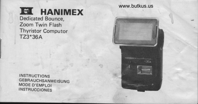
Hamimex TZ3*36A electronic flash User manual
User manual for Hamimex TZ3*36A electronic flash. 19 pages in German, French, Spanish. Read the original PDF, download or print a copy without registration.
19 pagesGerman, French, Spanish1.3 MB PDF
Loading your manual…Open PDF directly
Document details
- Brand
- Hamimex
- Model / document
- Hamimex TZ3*36A electronic flash
- Document type
- User manual
- Language
- German, French, Spanish
- Pages
- 19
- File size
- 1.3 MB
- Category
- Flashes & lighting
- Document date
- Not specified in catalog
Search available document text
Find a term, then jump to its page in the original PDF. Image-only pages may not be searchable; check the PDF for exact wording and diagrams.
Page 1 · Read text
www.butkus.usEil HANIMEXDedicated Bounce,
Zoom Twin Flash
Thyristor Computor
TZ3*36A


INSTRUCTIONS
GEBRAUCHSANWEISUNG
MODE D'EMPLOI
INSTRUCCIONES
View original page 1
Page 5 · Read text
TZ3*36A                  SPECIFICATION
Guide Number Main Flash      20m DlN21 (65ft. ASA100) on Wide 2
(High)                          25rn DlN21 (80ft. ASA100) on Wide 1
                       30m DlN21 (100ft. ASA10Ol on Standard
                       36m DlN21 (120ft. ASA100) on Tele
Guide Number Twin Flash      17m DlN2l (55ft. ASA10O) on Wide 2    I
(High)                   21m DlN21 (67ft. ASA100) on Wide 1
                       25m DlN21 (84ft. ASA100) on Standard
                       30m DlN21 (100ft. ASA100) on Tete
Auxiliary Flash (High)        7m DlN21 (23ft. ASA100)
Guide Number (Low)          One quarter the figure for High.
Coverage Angle               To suit down to 28mm on Wide 2 (using W/A Adapter),
                       3$mm o4 Wide 1, 50mm on Standard and 85mm on Tele.
Bounce                      0]to 90", detented at 0' and every l5o from 4soto 90o.
Macro                 5 Depression  for close-ups with safety latch.
Flash Duration                 1/1500 Second effective on manual, down to  l /2SOOO
                                second on auto.
View original page 5Page 6 · Read text
www.butkus.us
Recycle Time                7 Seconds with Alkaline cells (Manual).
Auto Check                1% Second display of yetlow l.e.d. and continuous beep
                                sound.
Auto-off Circuit               Power switches off when storage capacitor is fully charged.
                            Power reinstated automatically when fired or when on-off
                                switch re-operated.
Povrrer Source                 4 X AA, Alkaline cells preferred.
Battery Life                  180 Flashes on manual with Alkaline Cells (DlNl.
lndicator                     Green LED - Power on
                         Red LED, Beeper - on completion of charging "Ready"
                             Yellow LED, Beeper - Auto within range.Dedication                         :  Accepts Hanimex lntegrated Flash System (l.F.S.) modules
                                  to suit current & future cameras.
View original page 6Page 7 · Read text
INTRODUCTION                                   please, read these instructions, and those
The TZ3*364  is unique among dedicated        of your module, thoroughly.
flash guns in that all the circuit requirements
to suit your particular camera are all built      INSTALLING THE MODULE
into the IFS module. When the correct IFS           lf your dealer did not install the module
module is fitted, the TZ3t36A exactly suits       (1) to the flashgun proper (E) please proceed
your camera and operates all the flash inter-      as fo!lows:
face circuits your camera provides. Further-      1. Check the module type number on the
more, and contrary to most other dedicated         package and the module itself are the
flash guns, there are no circuits for other           same.
cameras extra to your needs that you have      2. Hold the flash gun, rear side uppermost
had to pay for. So now you can have all the           in one hand and the module, also rear
benefits of your camera's flash dedication            side uppermost but slightly tilted forward,
while enjoying the use of such an economic,           in the other hand. See Figure 1 .
compact, powerful, zoom bounce, twin        3. The flashgun has ribs (4) one in each side
flash gun complete with an audible monitor.         of its lower housing which have to engage
Full enjoyment cnnres with understanding so,         in slots (2) in the module. Further, the
View original page 7
Page 8 · Read text
www.butkus.us
   gun has a slot (24, fig 9l to accept the            are installed they will always push the
    circuit board tqngue (3) of the module.              lid open on operating the latch.
   Therefore enter the module into the gun     2. Take 4 AA Cells (Alkaline are preferred)
   housing so that the corners (6) iust rest         and load them in one after another
   on the start of the ribs as in Figure 2.            observing the polarity signs on the lid
4. Push the module in a little more and              contacts or observing the arrangment
    straighten  it up so that the tongue (31             in Figure 4.
    enters the slot l24l as in Figure 3.          3. Close the lid which will automatically
5. Finally push the module home, when it            latch.
    will be felt to lock into place.
                                 POWERING UP & TESTING
LOADING BATTERIES                     1. Switch on by moving the Power Switch
1. Push the lid catch (14) upwards to release         (15) from left to right (from 0 to 0).
   the battery lid (20), as in Girue 8. Note.        The green l.e.d.'Power'lamp (161 will
    In a new gun a tight lid (20) may not               light up to show that power is being
   open for without tapping the gun lightly        consumed. Check that the beeper switch
    in the palm of the hand. Once batteries           (29) is on.
View original page 8Page 9 · Read text
2. After a time (only a few seconds with         1% seconds accompanied by a continuous
    fresh batteries) the red l.e.d. 'Ready'            beep sound to confirm correct auto
   lamp (181 will light up and the beeper           exposu re thyristor action.
    will sound intermittently to indicate            5.  After carrying out (4) above, the red
    that the gun's capacitor is charged to at             l.e.d. (181 may go out but in any case ttie
    least 70% of it's capacity and is ready to         green l.e.d. will re-light to restore the
     fire.                                       power used.
3. The green Power lamp (16) will extinguish      6. Switch off by moving the switch (1S)
   a few seconds after the ready lamp lights.        to the left (O position).
   This is normal as pourer is only supplied
   to the charging circuit until full charge      AUTO.OFF CIRCUITRY
     is reached.                              The T23*364 employs a battery saving
4. Switch to one of the 'Auto' positions         automatic on-off circuit (AUTOOFFI such
   on your module and press the 'Test'           that, if you do not fire the flashgun,  it
   button (19) to fire the flash while pointing   disconnects the batteries from the power
    at some close object. The yellow Auto-         inverter stage, switching off the green ,power,
   check l.e.d. (17) will light up for about          l.e.d. as it does so. The red 'Ready' l.e.d.
View original page 9Page 10 · Read text
www.butkus.us
and Beep sound will remain on for some         using the flashgun for some weeks, it is
time indicating that the gun is still ready          better to remove the batteries to avoid the
to fire.                                                possibility of contact corrosion.
lf you fire the flash at any time, battery
power is automatically re-connectd and the    MOUNTING THE FLASHGUN TO YOUR
green l.e.d. lights up again until the used      CAMERA
charge has been restored to the flash           Always screw the lock-ring (111 fully upwards
capacitor.                                     before inserting the foot (10) into the
lf, after a long time without use, the red          accessory shoe of your camera. Push it right
'Ready' l.e.d. extinguishes, the gun may        home and then screw the lock-ring down to
be readied again by switching off and then      clamp the gun firmly.
on again.
A great advantage with this circuit is that      OPERATION
even if you forget to switch off the T23*36A   When you are about to use the flash, first
when putting the gun av\ray, you can safely     move the switch (1S) to the right loposition)
depend on the circuit disconnecting the          as described in POWERING UP & TESTING.
batteries. Naturally, if you do not intend       When the Ready Lamp (18) red l.e.d. lights
View original page 10
Page 11 · Read text
up or anytime the beeper is sounding inter-       shot. This speeds up the recycle time and
mittently you may trip your camerc shutter      reduces battery drain.
to fire the flash and expose your picture. The   No calculations are required for Automatic
flash will not fire if the Ready Lamp is not lit    Control other than to check that the subject
so please check for the 'Ready'signal. NOTE.       is witf in range. This you may do by using the
Most cameras will also show a 'Ready' indica-    Auto-Check facility, by using the Guide
tion in the viewfinder for greater ease of use.    Number, or by using the calculator.
AUTOMATIC CONTROL                AUTO-CHECK
Automatic control  is the simplest and most      Each time you use the T23*364 under auto-
economical way of using your flashgun.          matic control, the continuous Beep sound and
Basically, light reflected back from the          the yef fow l.e.d. (17) will be on for about 1/z
subject is integrated (either in your camerc or    seconds  if the subject is-within range.
in the flashgun) and when the correct expo-    NOTE. Some cameras have the facility for
sure has been reached, the flashgun  is           showing the auto-check signal in the view-
switched off by the series thyristor to ensure            f inder.
that any unused charge is saved for the next    When in doubt whether the shot you wish to
View original page 11
Page 12 · Read text
www.butkus.us
take is within automatic range you may test       First set the index mark (27) of the 'Distance'
on open flash by pressing the 'Test' button        slide to the zoom setting in use -T, S, W1, or
(19) and noting the presence or absence of    W2 (see section on USING THE ZOOM).
the yellow light or the Beep sound. NOTE.       Secondly set the index mark (28) of the
The range depends on your module as well as     'Aperture' slide to the film speed you are
the relative light absorbency of the subject        using. You may now read the appropriate
or background.                                   distance above any given aperture. In Figure
                                        1O it is to be noted that the Distance slide has
USING THE CALCULATOR                   been set to W1 and the Aperture slide to 100
The calculator slide rule (see Figure 1Ol has    ASA (DlN21). Note that there are two
two slidbs, one on the flashgun proper (the       operture scales on the Aperture slide. The
'Distance'slide (26)) and one on the module     upper scale is for full power manual or for
(the 'Aperture'slide (25)). Your module         automatic control while the lower scale is for
may have a different appearance to Figure 10    reduced power. (NOTE. These are switch
but the principle of operation is the same in      selectable. See your module instructions).
all cases. As well, full instructions are given     You may now look above the aperture you
with the module.                                  are using and read off the distance. ln Figure
View original page 12Page 13 · Read text
1O if you were using f2.8 at full power or on
automatic the distance is 3O feet (9 M). lf
you were using f2.8 on low power  it is 7 feet
(2 M).

GUIDE NUMBER
The guide number of a flashgun  is an indica-
tion of its power. Dividing the guide number
by the distance from the flash to the subject
gives the f number for the aperture to get
correct exposure at that distance on manual
operation. Alternatively, dividing the guide
number by the aperture in use will give the
distance for correct manual exposure or the
maximum distance for automatic control.
View original page 13
Page 15 · Read text
For example, you are using 4OO ASA (27         operation, particularly for motor-drive (up
 DIN) film you are shooting at f/4 3116 ysrr        to 2  f .p.s.) or fill in flash. Manual options
 have the zoom set to 'S'. The guide number  is    are selected by a switch in the module. See
200 feet (60 metre). Dividing this number by    your Module instructions for further details.4 gives a distance of 50 feet (15 metre).
 lf you were using low power then the distance   USING THE ZOOM
wouf d be 12%feet or 3/a metres.                Normally the zoom shroud (21) is clicked
                                                      into one of its 3 positions that suits the lens
MANUAL CONTROL                                     in use on your camera. The setting (Wl_35mm,
You will want to use Manual Control when     S-SOmm, or T-85mm) appears in the window
you wish to shoot at apertures that may not      (12). Ttre indication refers to the widest
be possible in Automatic Control. Generally      angle lens which that setting will adequately
you will use the high setting and use the          illuminate. Therefore always choose a setting
calculator or Guide Number to determine the    equal or lower than the focal length of your
distance or f/no. (see USING THE CALCU_        lens. For example,  if you have a 42 mm lens
LATOR and GUTDE NUMBER sections).       you could use the W1-3bmm (with or withoutYou may also use the low level manual          the wide angle adapter                                                                         - see below). The
                                                                                        13
View original page 15Page 16 · Read text
www.butkus.us
longer the focal length zoom setting you use      front of the zoom shroud (21 ) and operate
the greater the distance under automatic          the zoom in the closed-up W1-35mm position.
control or the faster the recycle time for a
given distance you can achieve.             USING BOUNCE
Again, for example, you may have a 135 mm      Particularly in portraits,  it is often preferable
tele lens on your camera. In this case, any        to soften the shadows by using bounce flash,
position will cover the subject field, but again,   wherein the subject is illuminated by
the T-85mm zoom position will give you the     bouncing the flash from the ceiling.
fastest recycle time or the greatest distance.      Apart from special effects, use the bounce at
You can, of course, use the T-85mm position    45 or 60 degrees to avoid having too much
for special effects with a wider angle lens so       light scattered back upsetting automatic
that only the centre of the picture  f ield is        operation. Just rotate the head (23) until the
adequately  illu mi nated.                          desired figure on the bounce scale (7) is
                                                    indicated by the pointer (8). Remember that
WIDE ANGLE ADAPTER (W2}                 the extra path length of the flash to the
To cover down to 28mm lenses it is necessary    subject together with the scattering of light
to snap the wide angle adapter (221 on the        at the ceiling surface will drastically reduce
View original page 16Page 17 · Read text
the distance over which automatic coriirol      CLOSE-UPS
can operate. By all means zoom out to the       For distances closer than 6 feet (2 M), even
T position to increase the distance, since        though the TZ has one of the lowest prof iles
ceiling scatter will diffuse the narrow beam       of its kind, the height of the flashgun above
into acceptable coverage with wider angle        the camera can cause the lower part of the
lenses. Also try a test flash with the Auto-        subject to be under illuminated.
Check circuit.                           To overcome this you may depress the
                                           bounce head (23) 5" below the horizontal.
USING TWIN FLASH                     Do this by sliding rhe macro latch (9) to the
Bounce flash alone, while preferable to the        right while depressing the head.
harshness of direct flash alone, needs a litile     Always remember to restore the head to the
direct lighting to eliminate shadows. This is      normal (0-) when you've completed your
the function of the auxiliary flash (30). To       close-up shots so all is in readiness for normal
use the two flashes together have the switch       flash photography. Just lift the head and the
(31) against the figure "2" above  it. For non-     latch (9) will slide out of the way auto-
bounce work use only the main  f lash by          matically.
having the switch against the  f igure "1 ".        The macro latch functions as a stop at 0o to
View original page 17Page 18 · Read text
www.butkus.us
pnevent accidental use of the depressed       CHANGING THE MODULE
head.                                        Normally you will never need to remove
                                               the module once it is installed. However if
USING SOUND MONITOR'BEEPER'          you change your camera you may elect to
The audible beep sound is to conf irm the       keep such a good flashgun as the T23*364
indications'Ready' and'Auto Check'           and purchase only an IFS module to suit your
displayed on the flash gun without taking      new camera.
your eye off the action or the view finder,        Figures 5 & 6 show how the module  is
so allowing you to concentrate more on         removed. Grip the module between index
picture composition.  lt is specially useful for      finger and thumb with the palm and the
cameras without such indications in the view     remaining fingers gripping the flashgun
finder. Even when using a camera with view      proper. Push the module upwards while
finder indications, you will find that the          depressing the catch (13) with a ball point
beeper is more useful, you can enjoy both.       pen. Once loosened, pull the module straight
When sound monitor action is desired, move      out.
switch (29) aginst the mark '0)))'. When
not required simply move it to 'Off' position.
View original page 18Page 19 · Read text
THE USE OF COLOUR FILTERS
The colour filters supplied with the TZ3*
364 may be used for special lighting effects.      F ilter     Flashgun used as    Flashgun used as
They simply clip over the front of the main      Colour     fill-in or secondary  sole or main lightflash (131. Since the Auto Sensor (11), which                  light
controls automatic exposure, is colour sensi_                                   Plus 1 stop
tive, it will not give correct exposure with       G reen        o           (F/NO)
coloured light. The flashgun must therefore
be used in the manual mode when using the      Red
flashgun filters.                                   Blue      Plus 1 stop        Pluslto2stops
Exposure must be increased according to the
colour used.


                                                                                        17
View original page 19Related documents and language editions
From the M. Butkus archive. Original publisher and archive notices are retained.
Check the model and edition against your equipment.
PDF verified 2026-10-10.