Film cameras
Hasselblad H1 film Pt. 2 User manual
User manual for Hasselblad H1 film Pt. 2. 33 pages in English. Read the original PDF, download or print a copy without registration.
33 pagesEnglish16.5 MB PDF
Loading your manual…Open PDF directly
Document details
- Brand
- Hasselblad
- Model / document
- Hasselblad H1 film Pt. 2
- Document type
- User manual
- Language
- English
- Pages
- 33
- File size
- 16.5 MB
- Category
- Film cameras
- Document date
- Not specified in catalog
Search available document text
Find a term, then jump to its page in the original PDF. Image-only pages may not be searchable; check the PDF for exact wording and diagrams.
Page 2 · Read text
36lnosseuan


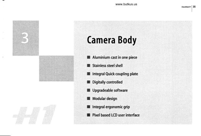
                                                                  The Hl camera body is a robust construction of cast aluminium with a
                                                                                  stainless steel shell for extreme durability. The workings of the camero
                                                                               are controlled by silicon chips that provide tremendous opportunities for
                                                                               sophisticated operation. To take just two examples, the mirror return is
                                                                    slowed down at the last moment by controlling the motor to decrease
                                                                                   vibrotions and the current usage of the camera, lenses, film magazines,
                                                                                     etc is recorded and freely accessible for service intervals, etc.
                                                                       The integral ergonomic grip houses the main control interface and also
                                                                            contains the battery holder. An auxiliary shutter in the rear opening of
                                                                        the camera body protects the film from exposure during the various
                                                                comera procedures. Please take extra care when handling the camera
                                                                 body without protective cover or magazine in place to protect the auxil-
                                                                             iary shutter. Likewise,thefront opening of the camera body revealsthe
                                                                        mirror when unprotected by o cover or lens. Do not touch or attempt
                                                                               to clean the mirror. Slight marks or some dust particles on the mirror
                                                                                          will not affect results. More noticeable problems, however, should be
                                                                    taken care of by a Hasselblad Authorized Service Center. The camera
                                                                 body also contoins theviewfinder screen, which can be easily removed
                                                                                     or exchanged without the use of special tools or adjustment procedures.
View original page 2Page 4 · Read text
Venmo @mike-butkus-camera  Ph. 2083
PayPal Name  Lynn@butkus.org      www.PayPal.me/lynnbutkus
View original page 4
Page 5 · Read text
38lnossenndn


                                              Holding the battery holder flat against the grip and aligning the two upper lugs with the slot in
                                                   the grip, slide  it back into position as far as it will go. Swing back the battery holder retaining
                                                       lever as far as it will go into the locked position.
                                                 Battery life is dependent on a number of variable factors and therefore cannot be exactly pre-
                                                         dicted, though the throughput  of up to 2,500 exposures should be expected. Ifthe camera is left
                                                inthe active state instead ofstandbyforlongperiods thennaturallythis  figurewillbereduced.
                                             However, a low-battery state is indicated as a symbol on the grip LCD. When the batteries are
                                                 almost completely exhausted, a warning message 'Low battery' will appear on the grip LCD. The
                                           camera will not function at all when this message appears and battery change is essential.
                                         The rechargeable battery pack is an optional accessory that replaces the standard battery
                                                     cassette. Please see specific user manual supplied with the rechargeable battery pack for
                                                further information.
                                        Viewfinder screen
                                            The Hl is fitted with a Spherical Acute-Matte D viewfinder screen for extreme brightness, clarity
                                        and even illumination. An optional accessory screen with a grid pattern is also available.
                                         To change a viewfinder screen: Remove the viewfinder to access the viewfinder screen. To                                      I
                                           remove the screen, place the tip of a ballpoint pen or similar in the viewfinder screen removal
                                                  lug and pull upwards. To replace the screen, position the right side of the screen in place so
                                                     that  it sits correctly in the recess. Place the tip of a ballpoint pen or similar in the viewfinder                                                                                                                                                                                                                                                                                                                                                              I
                                                screen replacement indentation and press downwards until the screen snaps into position.             I
                                           Tryto avoid touching either surface of the screen with bare fingers.
                                                         not attempt to clean the screen by immersing  it in water, or use any kind of      www.butkus.us                          /  Oo
                                               cleaningfluid,  If the screen becomes damp, do not use hot air to dry it, IIse a soft cloth
View original page 5Page 6 · Read text
www.butkus.us
                                                                                                                      H,rsehtodffil39


on the uPper surface only, Seek advicefro* an Authorized Hasselblad Service Center
if the screen becomes particularly soiled, Remember that particles or greasy marks on
the screen might impair the viewfinder image but have no effect vhatsoever on the
recordedimage,


On the left hand side of the camera body are two accessory retaining screw threads (M5), as
well as a databus connector, protected beneath a cover. Various accessories, an IR-remote
control for example, can be attached. The cover is removed by sliding it to the left.
PG.conn.79t9r.
A PC connector for non TTl-flash synchronisation is located on the left side of the body. It
is protected by a captive rubber
View original page 6Page 10 · Read text
www.butkus.us
                                                                                                                                              H4,]j',htadffil43


Parts & Components
A. Rubbereyecup
B. Hotshoe
C. Eyesight adjustment wheel
D. Exposure compensation button
E. Exposure method / mode button
F. Integralflash unit
G. Flash unit button
H. Viewfinder release button


While holding the viewfinder at a slight angle and resting  it on the top of the camera, slide
the viewfinder forward until the front locating pin is in position in the recess in the front
edge of the viewfinder screen aperture on camera body. Press the rear part of the viewfinder
firmly downwards until  it clicks into place.
Ensure that both sides of the viewfinder are seated correctly and that it has been firmly
attached. Failure to do so could cause an intermittent malfunction  if the databus interface
connections between the viewfinder and camera body are not positively secured.
To remove, grasp the viewfinder in the right hand and while depressing the viewfinder release
button, lift the rear of the viewfinder up and away from the camera body.
View original page 10Page 11 · Read text
44
    lna;llluoan


                                         Eyepiece adjustment
                                     No corrective lenses are needed to adjust the eyepiece to suit most requirements. The diopter
                                               range is from -4 D to +2.5D.Eyeglass wearers can rapidly and accurately change the settings
                                              according to whether they wish to wear eyeglasses for viewing or not.
                                                Personal eyepiece adjustments canbe carried outbypointingthe camera atthe skyor similar
                                             smoothly toned area. While holding the camera in your left hand, you can with your right
                                      thumb turn the adjustment wheel until the markings on the viewfinder screen reach the
                                      optimum sharpness for your eyesight.
                                                                           If you normallywear eyeglasses for distance viewing and intend to wear them for camera
                                            use then do not remove them for the above procedure.  If, on the other hand, you prefer to
                                           remove your eyeglasses for camera work, then repeat the above procedure without wearing
                                              your eyeglasses.
                                       Rubber eye cup
                                      Two rubber eye cups are available for the Hl. The one fitted is suitable for users who do not
                                              intend to use eyeglasses when photographing. The second shorter eye cup is for those who
                                                     either prefer to position their eye further from the viewfinder and those who wish to wear
                                                 eyeglasses.
                                         The eye cups can be rapidly changed by a Hasselblad Authorized Service Center.


                                              See section on'Flash'for full details.
View original page 11Page 13 · Read text
a6lns*nmn


                                                                    Att HC lenses have been specially formulated for the H system to produce the extremely high
                                            performance expected from Hasselblad to meet the demands from conventional and digital
                                            photography atike. tn addition to extreme sharpness, the design also incorporates a soft, pleasant
                                                    tooking bok€ (the visual quality of the out-of-focus areas of the image). All lenses feature an elec-
                                                         tronically controlled central shufter designed to extremely fine toleronces for supreme occuracy
                                                          that also provides flash synchronization up to  | /800s. All lenses have a very rapid automatic focus
                                                      capability with instant manual override. To ensure reliable and fast autofocus in low contrast and
                                          low tight conditions, a focusing-assist  light (on the grip) is automatically octivated. Aperture and
                                                       shutter control is set via the control wheels on the camera grip.
                                               As a general rule, lens shades should always be fitted to achieve optimum performance. Protective
                                                                      filters (I,JV / iky) should also be considered at least when working outdoors in harsh conditions.

            www.butkus.us            A. Lens shade index
                                   B. Manualfocus ring
                                 C. Focusing distance scales
                                  D. Depth-of-field scales
                                   E. Lens index
                                         Attaching a lens
                                       Remove the front protective cover on the camera body by depressing the lens release button
                                           and keeping  it depressed while turning the cover counter-clockwise. Remove the rear lens cap
View original page 13Page 14 · Read text
www.butkus.us
                                                                                   nannuan
                                                                                                   147


by unscrewing  it in a counter-clockwise direction. Align the index on the lens with the index
on the camera body and rotate the lens clockwise (bayonet fitting) until  it clicks into place.


Depress the lens release button and keep it depressed while rotating the lens counter-clock-
wise until  it stops and lift it out. Replace protective caps on the lens immediately and on the
camera body if necessary.
If you try to rotate the lens before you press the lens release button,  it might lock. In this
case, rotate the lens clockwise a little first and then re-attempt removal with the correct
procedure: button first, then lens.


Front lens caps are released for removal and attachment by inserting a thumb and index
finger into the recesses and pinching in the direction of the arrows.


Filters have a screw thread fitting (67 I 77 / 95 mm, according to lens) and are screwed clock-
wise into place. As there is no rotation of the front section of the lens when focus is changed,
filters do not rotate either. This is particularly useful when using polarizing or graduated
filters where the orientation is normallv critical.

Lens shades
All lenses are supplied with lens shades that additionally provide extra protection for trans-
port and storage when mounted in reverse. Lens shades have abayonet fitting and are turned
View original page 14Page 15 · Read text
4Slnosxnwnr


                                               clockwise into place after ensuring the index on the lens shade aligns with the index on the
                                                     front of the lens. When mounted in reverse, they are attached by matching the indexes and
                                              turning counter- clockwise.


                                            Both the shutter and aperture are electronically controlled and are adjusted by the control
                                           wheels on the grip. There are no separate manual setting rings on the lenses or camera
                                              body.
                                          The chosen settings are displayed both on the grip LCD and in the viewfinder LCD. See the
                                              'Exposure Control'chapter for a complete explanation.


                                              There are two distance scales (in feet and metres) visible through the focus distance window
                                              on the upper part of the lens barrel. There is also a central lens index mark and a depth-of-field
                                                       scale. The focusing distance is read off the chosen scale from the central lens index.
                                                  Depth-of-field can be calculated as follows:
                                                      l. Focusthe lens os required.
                                           2. Make on explswe rending (auto or nanuo| ond notethe opefture setting.
                                           3. Find the mnrkings on either side of the centrolindexfiot conespond to he chosen npertwe.
                                           4. Fron these two norkings, reod off on fte required lens distance scale the two conesponding distances.
                                         5. fhe depth-of-fietd (at that plrticular lpettwe ond focus sening) will be the orea included between these
                                                  two distonces.
View original page 15Page 16 · Read text
www.butkus.us
                                                                                                                           HalnhlodHl  | 49


                                                                                                                                                                                                                                                                                                                                                                                                           I


In the illustration given here, the focusing distance is set at nearly 3 metres. At an aperture
of fl22,the depth-of-field would therefore extend from just over 2 m to approx. 4.5 m.


A visual depth-of-field preview can be made by depressing the ST0P DOWN button while
viewing the image on the screen.


As infrared rays form an image at a different plane to that formed by visible light, the normal
focus settings do not apply. Proceed as follows in manual focus mode:
l.  Focus the lens in the conventionol monner until sotisfied.
2. Note the distonce sefting ogoinst the centrol lens indu.
3. Re-align this distonce sening ogoinst the infrored mork koloured red)insteod of the centrol lens index.
Alternatively  if you have already calculated the required distance, you can make a manual
distance setting by using the distance scales together with the infrared mark instead of the
central lens index.
Focus aid
As well as the conventional view on the focusing screen to ensure a sharp image, the Hl also
features LED focus aid appearing as two arrowheads to the right of the viewfinder display
(except for lenses with a maximum aperture of f16.7 or smaller). The arrowheads provide
confirmation  of a precision focus setting and are a useful support to a setting made with
eyesight alone.
View original page 16Page 17 · Read text
Manualfocus setting
When the left arrowhead alone appears  it means the focus setting is too far beyond the
chosen distance (the area framed within the central zone in the viewfinder) and when the
right arrowhead alone appears  it means the focus setting is too close. Focus is correct when
both arrowheads appear together. If the focus cannot be established, then both arrowheads
flash.
                               s ettingAutomatic fo cu s
Focus is correct when both arrowheads are visible together. Focus is incorrect  if only one
arrowhead is visible. If the focus cannot be established, then both arrowheads flash.
View original page 17Page 20 · Read text
www.butkus.us
                                                                                                             HajsrbtodmlS3


LCD panel                                                 A
The various functions are accessed by repeatedly pressing the function selector button (loop
menu) and changes made by the'change-up' and'change-down'buttons. Any settings are
automatically saved. At very low temperatures the LCD will require a few seconds to display
new settings.
LCD  ill u mi nation button
The LCD can be illuminated by pressing the display illumination button, which is accessible
when the magazine is not attached to the camera. The LCD will remain illuminated  all the
time you keep the button depressed, up to a maximum of l0 seconds. After l0 seconds has
expired, you must release the pressure on the button and press again to obtain a further l0
second period of illumination. Remember that using the illumination function very often
will noticeably shorten the life of the battery in the magazine.
Whenthe magazine  is attachedto the camera,the button onthe magazineis inaccessible but
you can still illuminate the LCD by pressing the illumination button on the grip instead.
Change up button O
Can alter the settings'upwards'. For example, to increase the film speed setting. Toggle
action.

                                                  DChange down button o
Can alter the settings'downwards'. For example, to decrease the film speed setting. Toggle
action.
View original page 20Page 21 · Read text
salnsnnnin


                                                       Selects the four functions that can be changed on the magazine. The functions are on a menu
                                             loop so that repeated pressing of the selector button will successively access all functions
                                                      in turn. After atime-out  of five seconds of non-activity, the display returns to the standard
                                                   screen.
                                                                                                        switch is in the unlocked                                                /   Chorg"s can only be made when the settings lock
                                                 position,


                                                  Provides a measuring point for the actual position ofthe film plane in the magazine. Sometimes
                                            used for calculations in critical applications.
                                            Darkslide indicator
                                                   Indicates whether the darkslide is in place or withdrawn:

                                                          stop  !          exposure CANNOT bemade                     R.ED =
                                                                        (magazine can be removed from camera)
                                                       ok  !            exposure CAN be made                           WHITE -
                                                                        (magazine cannot be removed from camera)

                                                                             If you attempt to make an exposure with the darkslide  is closed, however, you will receive a
                                           warning message in the viewfinder and grip LCDs - 'The darkslide is closed'.
View original page 21Page 22 · Read text
www.butkus.us
                                                                                    nannnam
                                                                                           155


Darkslide key                                         H
Withdraws and replaces the darkslide. Fold out the key and turn  it counter-clockwise 360o
(towards the open G symbol) to withdraw  it and clockwise 360' (towards the closed @
symbol) to replace it.
                                                                                        is attaehed to the canera./   fnt aoflcslide cm only be withdrawn when the magazine
Film tab holder                                                                                  ,
Holds an ID tab from the film roll pack as a reminder of the type of film loaded. Don't forget
to change it if you change film type!

Film holder key
Secures the film holder in the magazine. Fold out the key and turn counter-clockwise 90o to
remove the film holder and turn clockwise 90' to lock the film holder in place.
Magazine settings lock
All settings can be locked to avoid inadvertent changes. To change the settings, slide the
settings lock (see diag) to the right until  it stops. After the changes have been made, slide the
settings lock to the left (see symbol on magazine) again to secure the new settings.
Databus interface
Data interface between magazine and camera. Ensure the contacts are kept clean and
protected from damage. Keep the protective cover on when the magazine is being stored
or transported.
View original page 22Page 23 · Read text
56lnosscnmn


                                          The magazine uses a battery to retain information and settings when unattached from the
                                                .ur.ru. When attached to the camera body, the magazine takes its power requirements from
                                                    the camerabatteries. The magazinebatterywill normallybe effective for 1-2 years depending
                                        on use (off camera illumination, for example).
                                  When the battery is in a very low condition, (approx. 1 month of use left), a low-battery
                                           symbol appears onthemagazine LCD as awarning.
                                       The magazine will continue to functionwith no battery power left as long as it remains at-
                                             tached to the camera body. However, when detached, the settings will not be stored.


                 www.butkus.us
                                                                                                                          a counter-                                              Release the film holder by folding out the film holder key and rotating  it 90'in
                                                 clockwisedirection. Withdrawthi filmholder completely. onthebottom plate onthe inside
                                                              of the film magazine housing you will find a slotted circular battery cover. Insert a small coin
                                                   or similar into the slot and iotate the cover about 20' in a counter-clockwise  direction. The
                                                 cover will be freed and the battery can be removed. Replace with a fresh CR2032/ 3V lithium
                                                        (or equivalent) battery. Observe the polarity and ensure the positive (+) face is uppermost and
                                                     i.plu.. the cover (eniure the retaining lugs are inserted in the battery compartment slots),
                                                  loiking  it into place by rotating it in a clockwise direction until it stops. If you inadvertently
                                                   insertihe batteryincorrectly,the  film magazine witlnotbe damagedthoughitwillnot func-
                                                         tion. Try to avoid touching the surface of the battery with your bare fingers as sweat residue
                                             can decrease the electrical conductivity of the battery casing and might cause corrosion.
View original page 23Page 24 · Read text
www.butkus.us
                                                                                                                                 Horsehtod{l | 57


After battery replacement, the magazine's parameters return to the default settings (Barcode,
120, Data-on, Count up).


You cannot remove amagazine from the camera body  if the magazine darkslide is not in
place, (when the magazine darkslide indicator on the magazine shows white). Neither can
you withdraw the magazine darkslide when the magazine  is not attached to the camera. Both
these restrictions therefore prevent accidental film loss caused by fogging.
Attachment
Position the magazine retention groove onto the magazine support on the camera body
ensuring that they are correctly positioned. Swing the magazine towards the camera body
and firmly press into place with a click. If there is resistance, the magazine retaining catch
on the camera has probably been inadvertently released. In that case, push the release button
again to reset the catch.
You can attach and remove the magazine with or without the film holder in place. Ifyou just
want to change to a new film, you can remove and reload the film holder without having to
remove the whole magazine.
Removal
Ensure that the darkslide indicator on the magazine shows red (signifying that the darkslide
is closed). Firstly press slightly on the centre of the magazine release button and twist it clock-
wise until  it stops. Then press the button firmly inwards towards the camera body (see diag.)
to finally release the magazine.
/  n rure you prcss on the centre of the buttory not on the leven
View original page 24Page 25 · Read text
Stlnosseaan


                                            you cannotfetnove arnugazine if the darlcslideis not closed'                                           /                                                                                                                                   vill                                                            the film holder is inadvettently removed mid-fitm, then exposed frames                                           /      lf                                                                          b quickly te-in-                                               natwally be lost due to light fogging, However, if the flmholder
                                                   sertedrthefilmwitl automaticallybe advancedby threeframesto positionftesh
                                        unuposedfilm, Thefilm counter will also coffesponitingly ailil on three frames to
                                                       the iriginal number recorded before the film holder was removed.


                                                Press the @ button repeatedly to successively access:
                                  A. Film speed (lS0/ BarCode)
                                   B. Film length (12Ot22Ol Number of frames)
                                 C. Data (on/0ff)
                                   D. Frame counter (count down / count up)

                                        The film speed (Iso  / ASA) canbe set automatically or manually' Automatic settinguses a
                                            Barcode (only some films irave this feature). This is the default setting'
                                                                                                                                                       if the magazine is set at Barcode                                                           (ISO t filnlength) are automatic only                                                  /    f it^ rettings
                                          automatic, That is, a barcoded fiIm cannot overtide a manual settinghut a manual set-
                                             tingcan owrridethefiIm speed of abatcodedfilm'
View original page 25Page 26 · Read text
www.butkus.us
                                                                                                                                                                                                        Hasctbhdfl l59


                                            Films without a barcode must have their speed set manually. A manual setting must also be
                                    made  if you want to override the speed setting of a barcoded film.
                                             To access Manual setting:
 i:::l:::::,i,::i:
i,::::::::::r!::rl
::ltli:liiii,::l:li:::ti::l:::l:::                                    1) Ensure the LCD settings lock is in the unlocked position.
                                                                                                            (or barcode symbol) zppelrstogetherwithls0.                                 2) Presstne@ butnn until0figure
                                                                                            reach the required setting.                                 3) Press either the0 or theO button to
                                                                                            a time out of five seconds.                                   4) The new setting witlbe s1ved automatkolly ofter
                                    5) Retum the LCD settings lockto the locked position.

                                                            and b arcoded films  ( or ovenidden barco ded films ), check                       3  y you us e both standard
                                                that y ou have changed the s ettings accordingly,


                                       Both 120 and.2il}films can be used. 120 film will produce 8 (for use with'half-length' 120
                                                 films only) or 16 frames and 220 film will produce 32 frames'
                                                                         If the film has a barcode, then film length setting (and film speed setting) is automatic. The
                                     LCD will automatically show the barcode symbol and the appropriate film length. (Note that
                                                 film speed can be overridden with barcoded films, but not film length).
                                                                         If, however, the film has no bar code then proceed as follows:
                                              To access film type setting:
                                                                                                     lockis in the unlocked position.                                              l)  Ensurethe magazine settings
View original page 26Page 27 · Read text
60
    lnasennanr

                                   2) Pressthe@ button untilthel20 01220 synbol nppenrs.
                                                                                                                                                    possible ot barcode setting).                                   3) Press either theO 0r theo^ button to chonge the desired setting (not
                                       4) The new sefting will be slved nutomoticolly ofter timeout.
                                       5) Return the mogozine senings lockto the locked position.
           Manual film speed setting.
                                    Data imprint setting
                                                                               \
                                              Data imprinting can be activated or deactivated through the magazine menu.
                                                                                                                                 I               To access data setting:         lIFrw
           220 film length setting.                   1) Ensure the magozine settings lock is in the unlocked position,
                                   2) Presstnr @ button until the Data symbol appeors.
         EtrA  \           3) Press either the0 or trcO button to reochOn 0rOff.
                                                                                        \             4) The new setting will be saved automoticolly after o time out of five seconds.         |:|n                  \
            Data impd nting setting.                 5) Return the mogazine seftings lockto the locked position.
                                                 0peration and changes made to the data imprinting function are accessed through the camera
                                         menu. Please see separate section for full details.
                          t:t n              \                                   Frame counter setting                                    D
                                                                           \
              REM AIN                   The frame counter can be set to show either how many unexposed frames remain on a film                                                        \
                                                   or how many frames have already been exposed. The LCD shows your choice of setting by           Frames remaining| film counter setting.
                                             adding the word Remain as a reminder ofthe number of frames remainingor'countdown'.
                                            Absence of this word implies the opposite, namely,'count-up', so it denotes the number of
View original page 27Page 28 · Read text
www.butkus.us
                                                                                                                                                                                                                Hossehtodffi
                                                                                                                                           161


                                    the next frame to be used (for example, the figure 4 means three frames have already been
                                  exposed). This information  is also automatically displayed on the grip LCD and viewfinder
                           LCD though only as a figure above a symbol.
                                   To access frame counter setting:
                                      1) Ensure the mogazine settings lock is in the unlocked position.
                          2) Press the@ button untilRemain lppelrs.
                                                                                                                      (toggle function).                          3) Press either the0 bufton or the0 bufton to reoch the desired setting
                                                 'on' will show the number of fromes remaining
                                                'oFF' will show the number of the next frame.
                              4) The new setting willbe soved nutlmnticnlly  ofter a time out of five seconds.
                                     5) Return the mogozine  seftings lockto the locked position.


                           The low-battery symbol only appears on the magazine LCD when the battery needs
                                 changing. lF     rso   [l
                           Examplem
                                      In the example shown here:
                                    . 120 film length set manually
                                     . the film speed (150160) has been set manually
                                    . 5 frames have already been exposed (therefore with regular 120 film, 11 frames remain)-l hJ                                     . the battery  is functional
View original page 28Related documents and language editions

From the M. Butkus archive. Original publisher and archive notices are retained.
Check the model and edition against your equipment.
PDF verified 2026-10-10.