Sewing machines
Jones Spool — User manual
User manual for Jones Spool. 2 pages in English. Read the original PDF, download or print a copy without registration.
2 pagesEnglish0.6 MB PDF
Loading your manual…Open PDF directly
Document details
- Brand
- Jones
- Model / document
- Jones Spool
- Document type
- User manual
- Language
- English
- Pages
- 2
- File size
- 0.6 MB
- Category
- Sewing machines
- Document date
- Not specified in catalog
Search available document text
Find a term, then jump to its page in the original PDF. Image-only pages may not be searchable; check the PDF for exact wording and diagrams.
Page 1 · Read text
INSTRUCTIONS.

Jones SPOOL Machine

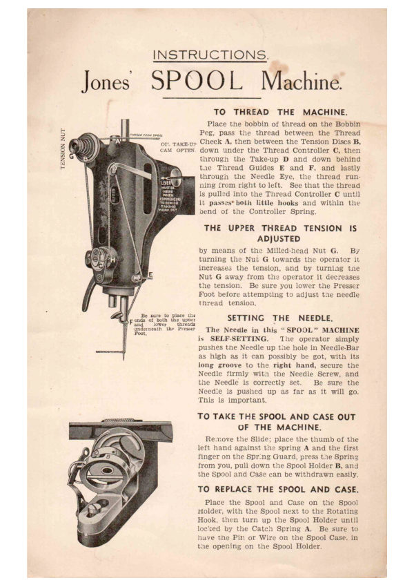
TO THREAD THE MACHINE.

Place the bobbin of thread on the Bobbin
meme wsn Peg, pass the thread between the Thread
on taxe.y> Check A, then between the Tension Discs B,
cant orrex. down under the Thread Controller ©, then
through the Take-up D and down behind
tae Thread Guides E and F, and lastly
througn the Needle Eye, the thread run-
ning from right to left. See that the thread
is pulled into the Thread Controller € until
it passes* both little hooks and within the
bend of the Controller Spring.

THE UPPER THREAD TENSION IS
ADJUSTED

by means of the Milled-head Nut G. By
turning the Nui G towards the operator it
increases the tension, and by turning tne
Nut G away from the operator it decreases
the tension. Be sure you lower the Presser
Foot before attempting to adjust tae needle
thread tension.

J ena tout dhe tosst SETTING THE NEEDLE.

Saderneatn the Pre The Needle in this “SPOOL” MACHINE
is SELF-SETTING. ‘The operator simply
pushes the Needle up the hole in Needle-Bar
as high as it can possibly be got, with its
long groove to the right hand, secure the
Needle firmly wit the Needle Screw, and
the Needle is correctly set. Be sure the
Needie is pushed up as far as it will go.
This is important,

TO TAKE THE SPOOL AND CASE OUT
OF THE MACHINE.

Remove the Slide; place the thumb of the
left hand against the spring A and the first
finger on the Spring Guard, press te Spring
from you, pull down the Spool Holder B, and
the Spool and Case can be withdrawn easily,

TO REPLACE THE SPOOL AND CASE.

Place the Spool and Case on the Spool
Holder, with the Spool next to the Rotating
Hook, then turn up the Spool Holder until
locxed by the Catch Spring A. Be sure to
have the Pin or Wire on the Spool Case. in
tae opening on the Spool Holder.
View original page 1
Page 2 · Read text
INSTRUCTIONS.

Jones’ SPOOL Machine.

TO FIX THE SPOOL IN THE SPOOL ¢
CASE AND TO ARRANGE THE
TENSION. as

A

LEAVE ONE INCH
OF LOOSE THREAD

Take the Spool Case in the left hand,
with the right hand place the Spool in the
- Spool Case, the thread on the Spool running
trom left to right (see arrow on engraving); pass the thread into the slot B,
drawing the thread under the Tension Spring C, as indicated by the dotted
lines, and out at D, as illustrated; be sure and never leave less than one inch
of Joose thread, as shown on the engraving.

By turning the Tension Screw A to the right you increase the tension;
by turning the Tension Screw A to the left you decrease the tension.

TO WIND THE SPOOL.

First disconnect the Balance Wheel by turning the large Milled-edge Nut
towards you. This will enable you to wind the Spool without running the
machine, and avoids the necessity of having to take the work from the
machine and breaking the thread.

Place the bobbin of thread on the Bobbin Peg, pull the Winder into contact
with the Belt, pass end of thread around the Spool two or three times, twisting
the thread together with the thumb and finger, then wind until the Spool is
filled. Do not wind the Spool too full.

TO ALTER THE LENGTH AND DIRECTION OF STITCH.

See the Stitch Regulator Handle near the Balance Wheel.

The highest position gives the longest forward stitch.

Depress the Handle to shorten the stitch.

Depress the Handle further to effect the reverse or backward stitch.

The lowest position gives the longest reverse stitch.

TO ALTER PRESSURE OF PRESSER FOOT.
Turn the milled-head screw at the top of the Presser Bar to the right to
increase the pressure, and to the left to decrease the pressure.
Always turn the Balance Wheel away from you, not towards you.
View original page 2
Related documents and language editions
From the ISMACS International. Original publisher and archive notices are retained.
Check the model and edition against your equipment.
PDF verified 2026-10-11.