Film cameras
KIEV 10 Translated via OCR - Google User manual
User manual for KIEV 10 Translated via OCR - Google. 15 pages in English. Read the original PDF, download or print a copy without registration.
15 pagesEnglish8.8 MB PDF

Loading your manual…Open PDF directly
Document details
- Brand
- Kiev
- Model / document
- KIEV 10 Translated via OCR - Google
- Document type
- User manual
- Language
- English
- Pages
- 15
- File size
- 8.8 MB
- Category
- Film cameras
- Document date
- Not specified in catalog
Search available document text
Find a term, then jump to its page in the original PDF. Image-only pages may not be searchable; check the PDF for exact wording and diagrams.
Page 1 · Read text
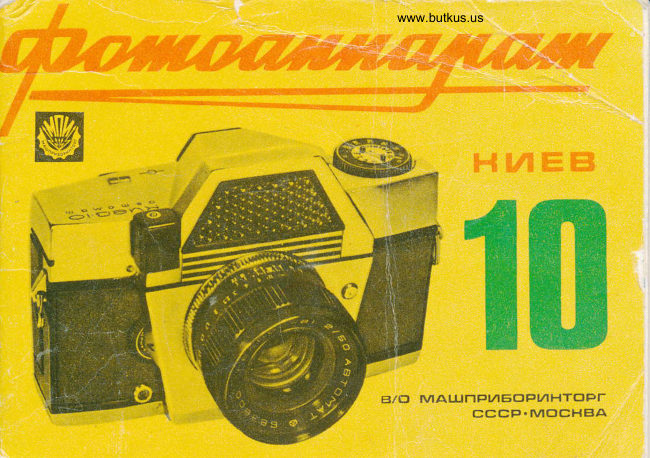
CAMERA
Kyiv-10
Brief Description


                       НИЕВ

                                                              В/ 0 МАШПРИБОРИНТОРГ СССР•МОСНВА


This is a translation from Russian to English via
OCR and Google translate.
View original page 1Page 2 · Read text
BRIEF DESCRIPTION: Before you begin taking photographs, carefully study the operating procedures for the
camera as outlined in this description.

Please note that this description contains only brief information regarding the camera's construction and
operating instructions; it is not intended to serve as a general guide to photography.

PURPOSE

The "Kyiv-10" is a high-class small-format single-lens reflex camera featuring automatic exposure setting.

The camera is designed for various amateur and professional photographic applications, and may also be
utilized in scientific and technical photography.

KEY SPECIFICATIONS

Automatic exposure setting is achieved through diaphragm control, regulated by a built-in exposure metering
system (shutter speed and film sensitivity are set manually in advance).

The exposure metering system operates within a brightness range of 16–16,000 nt (nits), with a film sensitivity
range of 16–500 GOST units.

The camera features a manual override function that allows for the deactivation of the automatic system and
the manual setting of the diaphragm aperture. When operating in this mode, the exposure metering system
remains active.

The shutter is of the fan type, featuring metal blades. The shutter is cocked via a lever mechanism, which is
interlocked with the film advance mechanism and the frame counter.

The viewfinder is a reflex type with continuous viewing (the mirror retracts only for the duration of the shutter
release). Focusing is performed using a micro-raster screen and a matte ring located at the center of the field
of view.

The viewfinder's design allows the user to compose shots while wearing eyeglasses.

The camera's back cover is hinged and swings open.
View original page 2
Page 3 · Read text
This camera has an "automatic"
                                         exposure mode.


                                                                                                                                                                  Digitally signed by Mike Butkus
                                Mike Butkus DN:org, cn=Mikeemail=mike@butkus.org,Butkus, o, ou=Butkus.c=US
                                                                                                                                              Date: 2026.05.04 20:59:01 -04'00'


   13

  12

Fig. 1. General view of the camera:

1 — Shutter release button;
2 — Frame counter window;
3 — Mark indicating the position of the film plane;
4 — Photoelectric cell with a raster lens;
5 — Shutter speed setting ring;
6 — Film sensitivity setting dial;
7 — Lens lock;
8 — Lens;
9 — Lens focusing ring;
10 — Flash synchronization socket;
11 — Distance scale;
12 — Aperture scale for depth-of-field determination;
13 — Dial for manual aperture setting and disabling automatic mode.
View original page 3Page 4 · Read text
The camera is equipped with a
flash synchronization contact
and a frame counter that
automatically resets to zero
when the back cover is opened.
Figures 1, 2, and 3 illustrate the
main components of the
camera.

Fig. 2. Bottom view of the
camera:
1—Film transport mechanism
release button;
15—Tripod socket;
16—Rewind crank.


                                                                                                                                                                               18

          2.1

Fig. 3. Rear view of the camera:

17 — viewfinder eyepiece;
18 — shutter cocking and film advance lever;
19 — hinged back cover;
20 — strap lug;
21 — film movement indicator window.
View original page 4Page 5 · Read text
TECHNICAL SPECIFICATIONS

Film width, mm. . . . . . . . . 35mm

Frame format, mm . . . . . . 24x36

Number of frames per roll. . . . . . 36

Main lens . . . . . . . . . . . . . . . . . . Helios 81

Focal length, mm. . . . . . . . . . . . 50mm

Relative aperture. . . . . . . . . . . . f/2

Focusing range, m. . . . . . 0.5m to infinity

Shutter speeds, s . . . . . . ½ to 1/1000 plus B

Viewfinder frame window dimensions, mm . . . . . . 22x44

Overall dimensions, mm . . . . . . 148 x 102 x 93

Camera weight (without case) . . . . . . 1080


Preparing the Camera for Shooting

Loading the Cassette

The cassette (Fig. 4) consists of three parts: the body, the spool, and the lid.

It must be loaded in complete darkness.

Before loading, the cassette must be disassembled; to do this, turn the lid counter-clockwise, remove it, and
take out the spool.

Trim the end of the film and firmly secure it in the slot of the spool. While rotating the spool, wind the film
tightly, holding it by the edges but without touching the emulsion layer—which faces the spool's core—with
your fingers.

When wound correctly, the film should not extend beyond the flanges of the spool. During winding, do not
attempt to tighten any loosely wound coils, as this may result in damage to the film's emulsion layer.

Insert the spool containing the film into the cassette body (Fig. 5a) and close it with the lid (Fig. 5b).
View original page 5
Page 7 · Read text
Fig. 4. Cassette


LOADING THE CAMERA
1. Remove the camera from its case.
2. Open the back cover 19
(see Fig. 3) by lifting the
rewind crank 16 (see Fig. 2)
and pressing the lock button
located beneath it.
3. Insert the rewind crank
into its socket.
4. Open the camera by swinging
the back cover open on its hinge.

Fig. 5. Loading the Cassette


            www.butkus.us

                              Image 6 loading the cassette
View original page 7Page 8 · Read text
5. Insert the film cassette into the compartment, pushing it firmly against the upper edge (Fig. 6).

6. Thread the end of the film leader into the slot of the take-up spool and secure the film by engaging a tooth
of the spool into a perforation hole (Fig. 7).

Before loading, rotate the spool in the direction indicated by the arrow on it to position the slot conveniently.

7. While holding the film and pressing it against the teeth of the transport sprocket with your left hand,
advance the film by turning the shutter cocking lever; verify that one of the sprocket teeth has engaged a film
perforation (Fig. 8) and that the film is winding onto the take-up spool.

8. Close the camera back.

9. Disengage the automatic aperture setting mechanism by rotating dial 13 (see Fig. 1) clockwise until any
specific aperture value aligns with the index mark; this is necessary because the shutter release button may be
locked under low-light conditions.


Fig. 8. Loaded camera

Fig. 9. Exposure and film sensitivity scale:

f — green dot (16 GOST units);
f1 — yellow dot (22 GOST units);
III — index for setting film sensitivity when shooting without a light filter


              www.butkus.us
View original page 8Page 9 · Read text
...films with a sensitivity of 130 units GOST (22–23 DIN) or 250 units GOST with a light filter. For all film
sensitivity values, the scale is locked in place. The filter factor of the light filter used for shooting can be
compensated for by the exposure metering device. To do this, when shooting with a light filter having a filter
factor of 2, the film sensitivity value is set opposite the index marked "C".

12. Activate the automatic mode by turning dial 13 (see Fig. 1) counter-clockwise until the letter "A" aligns
with the index.

TAKING PHOTOGRAPHS

The process of taking photographs with the "Kyiv-10" camera (Fig. 10) consists of the following operations:
cocking the shutter, setting the desired shutter speed, framing and focusing, and releasing the shutter.

Fig 10. Imaging by the camera


The shutter is cocked by rotating the lever as far as it will go (Fig. 11).  If the cocking operation is performed
completely, the lever automatically returns to its original position; if not, it remains in an intermediate
position. In this case, the bolt must be fully cocked.
View original page 9
Page 10 · Read text
www.butkus.us


 Fig. 11. Cocking the shutter                                                                  Fig. 12. Exposure settings


 Fig. 13. Focusing the lens

 Shutter speeds are set (Fig. 12)—whether the shutter is uncocked or cocked—by rotating ring 5 (see Fig. 1)
 until the selected shutter speed value aligns with the index mark on the top cover.

 Setting shutter speeds ranging from 1/1000 to 1/60 sec while the shutter is uncocked requires slightly greater
 effort than when the shutter is cocked, and may be accompanied by a faint clicking sound.

 The "B" (Bulb) setting is selected by rotating ring 5 in a counter-clockwise direction only (the ring is locked
 between the 1/1000 sec setting and "B").

 Focusing the lens (Fig. 13)—as well as setting it according to the distance scale—is accomplished by rotating
 lens ring 9 (see Fig. 1). At the center
View original page 10
Page 11 · Read text
Fig. 14. Aiming - a — the camera is not focused;


Camera Focus:

6 — Camera focused;

1 — "Low Light" indicator; 2 — Galvanometer needle;

3 — "High Light" indicator
View original page 11
Page 12 · Read text
Within the field of view of the viewfinder eyepiece, a small circle (micro-raster) surrounded by a matte ring is
visible. Lens ring 9 is rotated until the image—visible within both the circle and the matte ring—appears sharp.
Subjects are framed by viewing the image through the viewfinder eyepiece.

The viewfinder eyepiece's field of view displays an aperture scale (Figs. 14a, 14b) and a galvanometer needle,
which indicates the specific aperture setting that will be automatically selected when the shutter release
button is pressed. The dots marked on the aperture scale correspond to the values: 1.4, 2.8, 5.6, 11, and 22.

Depending on the specific combination of the film's sensitivity rating and the selected shutter speed, the
beginning and end sections of the aperture scale may be masked off by red indicators. If the needle rests
beneath the indicator at the beginning of the aperture scale (the "low light" position), it signifies that there is
insufficient light for photography. In this instance, the shutter release button is locked (the shutter will not
fire). The button may also remain locked if the needle is positioned very close to the indicator. To take a
photograph, it is necessary to increase the shutter speed until the needle deflects to align with the next
aperture value.

If the needle rests beneath the indicator at the end of the aperture scale (the "excess light" position), the
shutter release button remains unlocked. However, to obtain properly exposed (not overexposed) negatives,
the shutter speed should be reduced. If the needle aligns with any of the markings within the section of the
aperture scale located between the two indicators, a photograph may be taken by smoothly pressing the
shutter release button 1 (see Fig. 1). At this point, the lens aperture stops down, the mirror automatically
rises, and the shutter fires, after which the mirror lowers. Upon the return of the shutter button to its original
position, the lens aperture automatically opens.

If the brightness of the subject being photographed falls outside the 16–16,000 nt range for which the
exposure meter is designed, the needle will not emerge from beneath the indicator marks.

Depth of field is determined using the distance scale (11) in conjunction with the auxiliary scale (12); it can
also be verified by observing the details of the subject on the matte ring within the viewfinder's field of view.
To do this, you must press the shutter release button to stop down the lens aperture. If the shutter is cocked,
the release button should be pressed gently (not all the way down) to prevent the shutter from firing.

If the current aperture setting (the value of which is visible in the viewfinder eyepiece) does not provide the
required depth of field, you must adjust the shutter speed to achieve the necessary setting.

The exposure meter determines exposure based on the integral (cumulative) brightness of all objects falling
within the frame. When photographing subjects that differ significantly in brightness within the frame (for
example, a person against a snowy background), the exposure meter may fail to provide the correct exposure
for the primary subject.

When photographing dimly lit subjects, or whenever exposure correction is required, the automatic exposure
mechanism must be disengaged by rotating dial 13 (see Fig. 1) clockwise until the first dot aligns with the
index mark. Dial 13 features the letter "A" (for "Automatic") and an aperture scale. The unmarked values on
this scale correspond to the same aperture settings visible in the viewfinder eyepiece—specifically: 1.4, 2.8,
and 5.6. 11 and 22.
View original page 12
Page 13 · Read text
Preliminary setting of the aperture, with the automatic mode disabled, is performed by rotating dial 13 until
the selected aperture value aligns with the index mark. Upon pressing the shutter button, the lens
automatically stops down to the set value. Fig. 15a illustrates the position of the dial for manual aperture
setting with the automatic mode enabled; Fig. 15b shows the position with the automatic mode disabled and
the aperture set to 16.


              а                       6
Fig. 15. Position of the dial for manual aperture setting:

a — with automatic mode enabled; b — with automatic mode disabled and aperture set to f/16.


                         www.butkus.us
Pic. 16. Shutter release

When shooting with the "B" (Bulb) shutter speed setting, the automatic exposure control
mechanism must be disabled. If the automatic mode remains enabled, the camera will instead
set the aperture corresponding to a shutter speed of 1.5 seconds.
The camera shutter should be released by pressing the shutter button smoothly and firmly all
the way down, without tilting it (Fig. 16).
Do not press the shutter button if the winding lever 18 (see Fig. 3) is in an intermediate
position rather than its home position, as doing so may result in damage to the camera.
View original page 13Page 14 · Read text
Do not take photographs unless the automatic mode has been completely disabled (i.e., if the
dial 13—see Fig. 1—is stopped in an intermediate position between "A" and the first dot,
which corresponds to an aperture of f/22).


                                                                                    Fig. 17. Removable frame
FLASH PHOTOGRAPHY
The Kyiv-10 camera is equipped with a flash socket (10; see Fig. 1) for connecting a flash unit.
Flash photography may be performed with the automatic mode disabled, using shutter speeds
ranging from 1/60 to 1/2 second—settings which are highlighted in yellow on the shutter
speed dial.
The camera kit includes a detachable frame (Fig. 17) that can be mounted within the guide
slots on the eyepiece housing. This frame is designed to serve as a mounting bracket for
certain types of flash units.


LENS CHANGING
The design of the "Kyiv-10" camera is engineered for use with specialized interchangeable
lenses.
To remove a lens, press the release button 7 (see Fig. 1) and, while rotating the lens
counter-clockwise, withdraw it from the camera body.
To mount a specialized interchangeable lens (Fig. 18), it is necessary to align the red
dot on its base with the corresponding dot on the camera body, press the release button,
insert the lens into the camera's bayonet mount, rotate it clockwise until it stops, and release
the button.
Then, by rotating the lens slightly in the reverse direction, verify that it is securely locked in
place.
View original page 14Page 15 · Read text
The lens release mechanism is kinematically linked to the stop for the "low light" indicator
located within the viewfinder eyepiece's field of view (see Fig. 14); its position
depends on the maximum aperture of the interchangeable lens.


When an interchangeable lens is installed, the arm of the indicator moves, overlapping the
previous aperture value, thus taking into account the aperture value of the installed lens.
For example, when installing a lens with a 1:2 aperture ratio, the arm of the "light ratio"
indicator should overlap the extreme point corresponding to the 1:1 aperture value.


...and how, in this process, damage to the anti-
reflective coating may occur.
Do not expose the photocell of the exposure
metering system to very bright light during
intervals between shots. Prolonged exposure to
bright light causes "fatigue" in the photocell,
which temporarily affects the accuracy of its
operation.
Keep the photocell window clean.
Contamination of the raster lens may
compromise the accuracy of the automatic         Pix 20, rewinding the film
exposure control mechanism.
                                      The shutter blades are made of thin steelWhen bringing the camera indoors from
                                                ribbon. When loading the camera, take carefreezing temperatures into a warm room, do
                                              not to damage or deform them, as this couldnot open it immediately; instead, leave it inside
                                               lead to shutter failure.  If you discover anyits case for a while to allow it to warm up.
                                                 defects or damage, do not attempt to repair theDo not apply excessive force when handling
                                                   unit yourself. Repairs and adjustments to thethe camera.
                                         camera should be performed only by qualified
                                                       specialists..
View original page 15Related documents and language editions
From the M. Butkus archive. Original publisher and archive notices are retained.
Check the model and edition against your equipment.
PDF verified 2026-10-10.