Film cameras
Kiev-4 and Kiev-4A User manual
User manual for Kiev-4 and Kiev-4A. 32 pages in English. Read the original PDF, download or print a copy without registration.
32 pagesEnglish9.7 MB PDF
Loading your manual…Open PDF directly
Document details
- Brand
- Kiev
- Model / document
- Kiev-4 and Kiev-4A
- Document type
- User manual
- Language
- English
- Pages
- 32
- File size
- 9.7 MB
- Category
- Film cameras
- Document date
- Not specified in catalog
Search available document text
Find a term, then jump to its page in the original PDF. Image-only pages may not be searchable; check the PDF for exact wording and diagrams.
Page 2 · Read text
The camera you have bought may slightly
differ in appearance from the pictures pre-
sented in this booklet, since in manufacture
the appearance and performance of the ca-
meras are continuously improved


                                      *
View original page 2Page 3 · Read text
www.butkus.us


                  CA'VlERA

                 KIEV

                             INSTRT,I.CTIONS


ViO MASHPRIBORINTORG                   O USSR O  MOSCOW
View original page 3Page 6 · Read text
www.butkus.us


         Fig. l, b. Camera "Kres-4A" ("Kiev-4A")


            APPLICATION
"l(neB" ("Kiev") is a small-size high-quality camera in-
tended for both amateurs and professionals. lt can also be
used in scientific research and technical photography.
Two models of "(neB" ("Kiev") camera are available:
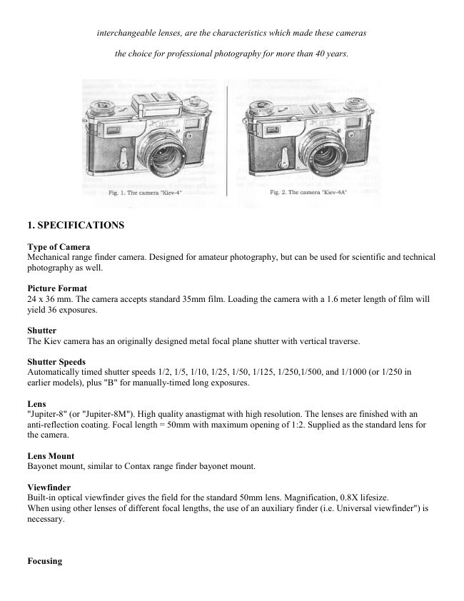
"Kiev-4" (Fig. l,al with a photoelectric exposure meter,
and "Kiev-4A" (Fig. l, b) without the exposure meter.
View original page 6Page 7 · Read text
BASIC DATA
Frame size on the negative 24X36 mm. Loaded with a
1.6 m long film the camera will produce 36 pictures.
The shutter is of a slotted type with hinged metal cur-
tains.
The shutter cocking mechanism is interlocked with the
film rewind mechanism, which precludes double exposure
of one and the same frame.
The coated lens "lOnnrep-8M" with focal length .F:5 cnr
and relative aperture I  : 2 is used in the camera.
Focusing is effecte{ with the aid of an optical range tinder
within 0.9 m to oo.
View finding is effected by use of an optical view finder.
The view finder and the range finder are combined and
have one eyepiece.
The camera is fitted with a self-timer providing a 9-15 se-
cond lapse before shutter opening at any preset shutter
speed.
The camera back is removable.
The "Kiev-4A" model is fitted with a film speed indicator,
the "Kiev-4" model   with a high-sensitive small-size pho-                     -toelectric exposure meter.
Both models of "Kiev" camera have a svnchrocontact for
operation with single-flash and multi-flish lamps.
For convenience in diaphragm setting after lens focusing,
the diaphragm scale is marked twice on the opposite sides
of the ring.
The general view of the "Kiev-4A" camera is presented in
Fig. 2, the "Jupiter-8M" lens is shown in Fig. 3.

4
View original page 7Page 11 · Read text
www.butkus.us

          Fig. 3. "Jupiter-8M" lens:
               /   dlaphragm rlng;  2   distance scale; 3          depth-    of fleld scale       -


        CAMERA LOADI NG
    PREPARING THE CAMERA FOR LOADING
t. Remove the camera from the case, having undone the
buttons and the screw on its bottom.
2. Swing two clips 3 (Fig. 4) of the camera back locks
and give them half a turn in the directions indicated in
Fig. 6.
3. Move camera back 2 (Fig. 5) slightly to the camera
bottom and detach it. In so doing be sure to hold the ca-
mera with its upper cap down, lest the cartridge and the
take-up spool should fall out.

6
View original page 11Page 12 · Read text
www.butkus.us


 Fig. 4. Camera bottom view:
           nut: 2                                                                  offton; / - tripodJ               back-,film.lock-cJiil"""transport mechanlsm"'"        cut       - camera


Fig. 5. Camera rear view:
/   range flnder,,vlew finder eyeplece; 2 _ camera back  -
View original page 12Page 13 · Read text
Fig.     6.   Opening
locks   on  camera
back


    Fig. 7. Removing
   .camera back
View original page 13Page 15 · Read text
Fig. 9. Cariridge loading


               Fig. 10. Closing
                   cartridge with caP
l0
View original page 15Page 16 · Read text
www.butkus.us

            CAMERA LOADI NG
The camera can be loaded in daylight, but poorly-lit pla-
ces are prtiferable. The procedure iJ as follows:
l. Fix the loose end of the film in the take-up spool.
2. Place the cartridge into the left-hand seat and the take-
up spool into the right-hand seat of the camera housing;
see to it that the film perforation engages with the teelhof the film transport drum (Fig. ll).
The emulsion-coated side of the film shourd face the lens.


    Fig. ll. Camera loaded  with cartridge and take-up
    spool
                                                                                  tl
View original page 16Page 17 · Read text
3. Close the camera (Fig. l2). Place the camera back so
that its edges enter the slots in the camera housing. Hold-
ing the edfe of the film with the thumb of your left hand,
push the camera back as far as it will go, turn the clips
of the locks and release them.
In the process of camera loading the  film loose end is
exposed. To advance the non-exposed  film to the frame
window, cock the shutter twice and  release the button
everv time.
lf the camera is loaded properly, the film rewind knob will
rotate when the shutter cocking knob is turned.
 lf the film is loosely wound on the cartridge spool, the
rewind knob will be immobile while the first frames are
being shot.


                                   Fig. 12. Closing
                                   camera back
t2
View original page 17Page 18 · Read text
www.butkus.us

 4. Align the frame counter zero with the index on the
 cover, turning the protruding part of the disc (Fig. l3).
 5. Set indicator 16 (see Fig. 2) of film-in-us'e speed to the
 proper value by turning the scale button and finding in
 film rewind knob l7 the appropriate figure. Engraved- orr
 the scale are figures corresponding to the speed of the
 film in GOST and ASA units and coded svmbols for co-
 lour film:z
    lor daylight                          for artificial lighting


Fig. 13. Zero-setting frame
counter

                                                                     t3
View original page 18Page 19 · Read text
SHOOTI NG
Shooting pictures runs down to the following procedures:
shutter cocking, exposure time setting, diaphragm setting'
view finding and focusing, shutter release.
Shutter cocking is effected by turning the shutter knob        I
clockwise (one complete turn to the stop); exposure time
setting is attained by turning the same knob, pulled out                                                       Ithis time, till the black dot on it is aligned with the desir-
ed exposure time value (FiS. l4). In this position theknob
is lowered till fixed.
With the shutter cocked, exposure time changing trom
lower to higher values demands for somewhat greater
effort than in the reverse direction.


                                                                                  I
                                                I

                    Irig. 14. Shutter sPeed setting
t4
View original page 19Page 20 · Read text
www.butkus.us

           It ts recommended:
      ohen changing from higher to loaer exposure time set-
        tings to turn the shutler coching hnob so that the blttck
         tlot is someahat farther than the selected exposure time
         uttlue and after that, rotating the hnob in the reuerse di-
        rection (clockaise), to align it utith the desired mark and
       loaer the knob;lt        ,set the exposure time af ter shutter cocking.
      The diapirragm (Fie. 15) is set by turning ring ,t (see
        Fig. 3) which is fixed when the index is aligned with any
        value selected.


II

                        Fig. 15. Lens diaphragming

                                                                                                                       l;r
View original page 20Page 21 · Read text
Focusing and range finding (Fig. 16) are effected by ro-
 tating disc 1J (Fig. 2), which is possible only after pres-
 sing lever 12 tixing the lens in the "m" (infinity) posi-
 tion.


                       Fig. 16. Focusing


t6
View original page 21Page 22 · Read text
www.butkus.us

       In the middle of the field of vision of the range finder/view
       finder you will see a brighter rectangular area where the
       subject viewed has a double image.
      Focusing consists in combining the two images into one
        (Fig. l7).
         It is recommended to combine the two images within the
       centre of the field of the smaller rectangular area.
          lf the distance to the subject to be photographed  is known,
       locusing can be effected by using the distance scale.
     To this end, turn disc /J (FiS.2) till the desired mark on
       distance scale 2 (Fig. 3) is aligned with the index dot of
       scale J.
      The depth of field is determined by the distance scale de-
      pending on the distance to the subject to be photographed
      and on the diaphragm selected.
      N o t e.  Shooting wlthout the range finder is recommended with
       considerable lens diaphragming, when the errors in determining
       the distance visually are corrected by the lens depth of field.


t                     Fig. 17. Combining images


                                                                            17
View original page 22Page 23 · Read text
Example. The.F:5 cm lens is set for a sharp image
of a subject located at a distance of m from the filnr
 plane. With diaphragm  value 8 all the subjects located
 within 2.5 to l0 m will produce a sharp image (Figs. 18,
 le).
N o t e. All the distances to the subject are counted off from thecamera film plane.
View finding is effected through the range finder/view
finder eyepiece while focusing the camera.
Within the eyepiece field of vision you will see exactly the
subject that will be obtained within the negative.
Shutter release (Fig. 20) is effected by depressing smooth-
ly shutter release button l0 (Fig.2).


 Fig. 18. Setting lens at       Fig. 19. Setting lens at
 2.5 m distance                4 m distance

When taking pictures with the "8" exposure time the shut-
 ter will remain opened while the release button is de-
 pressed.
To obtain longer exposure time, the release button can be
 fixed as depressed by turning it  fully counterclockwise
 ( Fig. 2l ).
The shutter will be closed after the release button is turn-
ed in the reverse direction till the red dot on it is aligned
with the dot on the shutter cocking knob, and the finger
is removed trom it so that it is no longer depressed
r8
View original page 23
Page 24 · Read text
www.butkus.us


      Fig. 20. Shutter release       Fig.2l. Shooting at
                               low shutter sPeed


The shutter can also be released automatically by use of
the self-timer mechanism.
                                                                4self-timer cocking is eltected by fully turning lever
(Fig. 2). For the procedure refer to Fig' 22'
                                                                          inTo actuate the self-timer move button 5 (see Fig. 2)
                                                         lapsethe direction shown by the arrow on it. The time
offered by the selt-timer betore the shutter is released  is
within I to 15 s.
Exposure time "B" with the self-timer engaged is within  I
                                    advisable to check  itto 3 s for diflerent cameras (it is
using a stopwatch prior to operating the camera)'
                                                                  t9
View original page 24Page 25 · Read text
Fig.22. Self-timer lever cocking

      UNLOADING THE CAMERA
 To remove the exposed film from the camera, rewind  ir
 back into the cartridge. To this end, depress the button
 disengaging the film transport mechanism and turn the
 film rewind knob in the direction shown bv the arrow
 (Fig.23).
N o t e.  In           the "Kiev-4"                     camera the film rewind knob should  bt: previously           pulled                      out.
Rewinding over, remove the camera back, take out the
cartridge and pull the film end out of the take-up spool.
Prior to closing the camera, examine  it and, if  required,
clean it with a brush or wipe it with a clean napkin.
20
View original page 25Page 26 · Read text
www.butkus.us


                     Fig. 23. Film rewind


  APPLICATION OF EXPOSURE METER
As distinct from the "Kiev-4A" camera, the "Kiev-4"
(Fig. l,a) model is fitted with a photoelectric exposure
meter arranged in the upper part of the camera.
As its name implies, the exposure meter is designed to set
the exposure time. lt consists of the lollowing main ele-
ments: the photocell located behind ribbed plate 1 (Fig.
25), calculator 2, galvanometer with pointer 1 (Fig. 2a)
and scale 2.
The calculator is fitted with an exposure time scale arrang-
ed on ring 5, as well as with film speed scale in ASA and
GOST units (the scale is combined) and diaphragm scale
located on disc 4.
                                                                   2l
View original page 26Page 27 · Read text
To select the exposure time, proceed as follows:
rotate disc 4 to set the film speed value against index Ion disc J. lf the camera is loaded with a film whose speed
is not indicated on the scale (e.g., 45 units to GOST or
ASA), align with the index 1| the middle of the disc sec-
tion between the 32 and 65 figures;
aim the camera at the subject to be photographed and
press the button to open the photocell cover (see Fig.25);
set the galvanometer pointer to index O of galvanometerscale 2 by turning ring 5 of exposure time scale (Fig.24);
referring to exposure time and diaphragm scales of the
calculator, determine the required exposure time. The red
figures on the exposure time scale denote seconds, the
 black figures - second fractions;


         32
              Fig.24. Exposure meter top view


22
View original page 27Related documents and language editions
From the M. Butkus archive. Original publisher and archive notices are retained.
Check the model and edition against your equipment.
PDF verified 2026-10-10.