Film cameras
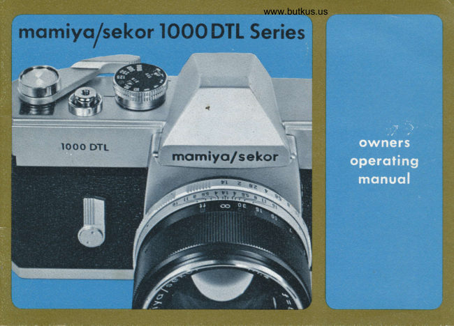
MAMIYA 1000DTL DIRECT User manual
User manual for MAMIYA 1000DTL DIRECT. 31 pages in English. Read the original PDF, download or print a copy without registration.
31 pagesEnglish11.1 MB PDF
Loading your manual…Open PDF directly
Document details
- Brand
- Mamiya
- Model / document
- MAMIYA 1000DTL DIRECT
- Document type
- User manual
- Language
- English
- Pages
- 31
- File size
- 11.1 MB
- Category
- Film cameras
- Document date
- Not specified in catalog
Search available document text
Find a term, then jump to its page in the original PDF. Image-only pages may not be searchable; check the PDF for exact wording and diagrams.
Page 3 · Read text
www.butkus.us
TABLE OF CONTENTS

 Description of Reference                                         3
Section 1.   Specif ications ..........                                5
Section 2.  lnsert the Silver Oxide Battery                       7
Section 3.  Film Loading .........                               8
Section 4.  Setting the Film Speed                               11
Section 5.  Selecting the'Shutter Speed....                      t2
Section 6.  Focusing and Viewing .............                      13
Section 7.  Setting the Exposure  ...                           t4
Section 8.  Depth of Field....                                  t7
Section 9.  The Automatic Lens.                               19
Section 10.  Changing the Lenses  ............                    20
Section 1 1.  Holding the Camera.............                       2l
Section 12.  Self Timer                                    22
Section 13.  Flash Photography                              22
Section 14.  Rewinding the Film                               23
Section 15.  Helpful Hints                                  24
Section 16.  Troubleshooting Your Camera .........               25
Section 17.  Meter Cut Off Points                            27
View original page 3
Page 7 · Read text
SPECIFICATIONS:            momiyo/sekor  l OOO DTL CameraI
   CAMERA TYPE:        35mm Single Lens Reflex with two separate behind'the'lens metering
                                 systems'--one for spot readings, one for averaging type readings.
   FILM SIZE AND CAPACITY: 35mm  f ilm (perforated) in 2Q or 36 exposure standard cartridges.
   STANDARD LENSES:      55mm t/L.4 momiyo/sekor. 7 elements in 5 groups. Angle of acceptance:
                       43 degrees.
                      55mm t/I.8 momiyo/sekor. 6 elements in 4 groups. Angle of acceptance:
                       43 degrees.
   LENS MOUNT:              Praktica-momiyo/sekor, 42mm universal threaded mount.
   LENS ACCESSORY SIZE:   55mm  f /1.4 Lens: Acc{ftslm   threaded  f ilters and other lens accessories.
                      55mm t/L.8 Lens I Acc{flmm  threaded filters and other lens accessories.
   SHUTTER:                  Focal plane type with speeds from 1 to L/LOOO of a second and " B " for
                             time exposures. Built-in variable delay self-timer.
   EXPoSURE coNTibL:     Two separate metering systems with one CdS meter cell positioned on the
                          back of the reflex mirror (spot system), and one cell located on each side
                                of the viewfinder eyepiece, in the penta-prism housing (averaging system).
                              Both metering systems are cross-coupled to camera shutter speeds and dia-
                         phragm mechanism of all automatic lenses with Praktica-momiyo/sekor
                                   universal mounts. Film advance lever switches metering system on and
                               actuates diaphragm of automatic lenses. Metering systems also accurately
                            measure light transmitted through non-automatic lenses, bellows, extension
                               tubes, filters and other lens attachments. Spot/Averaging selector switch
                         on camera body allows use of either the spot or averaging system of ex'
                               posure calculation.
    FILM SENSITIVITY:       ASA 25 to 320O     DIN 15 to 36
*        Patent pending on momiyo/sekor Spot/Average Metering System.  ryna:
View original page 7Page 8 · Read text
www.butkus.us
With Spot and Average Metering System

     VIEWFINDER:                Penta'Prism type with micro diaprism center spot on Fresnel lens for rapid
                               focusing. Brackets visible in finder indicate location of spot meter reading
                              area (6ok of  f ield). Pointer and " S " and " A" symbols visibte in  f inder
                                   indicate whether the spot or the averaging metering system is being used.
                               Exposure needle and reference points indicate necessary exposure adjust.
                                  ments.
    FLASH SYNCHRONIZATION: With Focal Plane bulbs:    to 1/1O00 second.
                              With Class "M" bulbs:     to 1/3O second.
                              With Class "F" bulbs:     to 1/30 se'cond.
                             With Electronic  f lash:      to l/60 second.
                            The momiyo/sekor looo DTL has two separate sets of flash contacts,
                           marked " FP " and " X ".  Proper selection of terminals allow correct synchro.
                                   nization for all types of flash exposures.
    REFLEX MIRROR:             lnstant Return Type.
    FILM ADVANCE:             Ratchet type film advance lever transports fitm, cocks shutter and advances
                             exposure counter in a single stroke (160") or by a number of shorter
                                       strokes.
    EXPOSURE COUNTER :      Progressive type, from " S " (start) to 36. Counter automaticalty resets to
                                           " S " when  f ilm compartment door is opened.
    DIMENSIONS:           Width:    5.8 inches (148 mm)
                                 Height :    3.7 inches ( 95 mm)
                            Thickness: 2   inches ( 5L mm) without lens.
    WEIGHT:                 Body only: I  lb. 9-I/2 ounces lT2Sgramsl
View original page 8Page 9 · Read text
INSERT THE SILVER OXIDE BATTERY:

                                 The Silver Oxide battery supplied with the camera is especially
                                          designed to operate the two metering systems of the momiyof
                                       sekor lOOO DTL camera. No substitutes, other than those listed
                                        below can be used. lnstall as follows
                             TO OPEN THE BATTERY COMPARTMENT, place the tip of your
                                    thumb or forefinger on the knurled surface of the compartment
                                       cover (19), and twist counterclockwise until all threads have
                                      been disengaged.  lf the cover is too tight, use a coin to start
                                   the operation, but remove the coin after a quarter turn and
                                          complete the removal of the cover using only your thumb or
                                                                                                                     f oref inger.
                                             Insert the battery negative (-)  side down (refer to Figure A).
                                        Replace cover carefully, making sure that the threads are pro-
                                         perly engaged. Again use only your thumb or forefinger, this
                                        time using a clockwise twist until the cover is tight. DO NOT
                                            tighten cover with a coin.Fntte.l t?t1{'rcJ 8-Q-xl.
                                   The battery will last for approximately a year, depending upon
                                        use. To replace, use one of the following Silver Oxide batteries:
                                        Eveready S-76E, Mallory MS-76, or Ray-O-Vac RS-76.
View original page 9Page 10 · Read text
www.butkus.us
      FILM LOADING:


     DO NOT LOAD IN BRIGHT LIGHT.
       Open fifm compartment door (271
       of camera (refer to Figure B) by
        pulling upward on the slide lock
                     ( 13).
View original page 10Page 11 · Read text
,{


                                                          rigure o                         Figure E                                                     f

                                                                                                    passPull uo the rewind knob (12) as   Draw out the film leader (refer   NOTE :  The film must
in Figure C. Place film cartridge    to Figure D), and insert the end    under the take-up spool when
                                                                                                                                              E).into film chamber (181, and    of the film into one of the slots    advanced (refer to Figure
return rewind knob to its former   on the take'up spool (25).  lf
position.                      no slot is in the correct position
                              for insertion of the film, the
                                 take-up spool may be rotated by
                            hand until the slot is accessible.
View original page 11Page 12 · Read text
www.butkus.us


                         Figurb C                                                         Figure E

                                                                                              passPull up the rewind knob (12) as   Draw out the film leader (refer   NOTE: The film must
                                                                                        whenin Figure C. Place film cartridge    to Figure D), and insert the end    under the take-up spool
                                                                                                                                              E).into film chamber (18), and    of the film into one of the slots    advanced (refer to Figure
return rewind knob to its former   on the take-up spool Qsl.  lf
position.                     no slot is in the correct position
                              for insertion of the film, the
                                 take-up spool may be rotated by
                            hand until the slot is accessible.
View original page 12Page 13 · Read text
Refer now to the exposure counter (4) window. The letter " S "
                                      should appear opposite the triangular index mark in the exposure
                                     counter window. Next, Gently turn rewind knob in the direction
                                      of the arrow just enough to take the slack out of the film.
                                 Depress the shutter release button (6), and advance the film
                                    again by rotating the film advance lever as far as it will go in
                                    the direction of the arrow. The shutter is automatically cocked
                       Figure F     when the film advance lever is moved to  its farthest point.
                                 Repeat this action until the  f igure " 1 " appears opposite the
                                                                                             TheAdvance the film with the film      triangular index mark in the exposure counter window.
advance lever (refer to Figure F),     camera is now ready for taking the first picture.
while noting the reverse rotation                          NOTE: As the film is advanced, the rewind knob will periodical-of the take-up spool. Make sure                                            ly rotate in a backward direction. This indicates that the filmthat the sprockets are engaged as                                          is being transported correctly in the camera.the  f ilm passes over them, and
that one complete wind of  film
is around the take-up spool. Close
f ilm compartment door, making
sure that it is locked.


                                                                                             10
View original page 13Page 15 · Read text
SELECTING THE SHUTTER SPEED:

                         The 12 numbers on the outer face of the shutter speed dial
                              are speed settings, and represent fractions of a second. For
                              example, (refer to Figure l), the number 125 on the dial (opposite
                           the engraved reference mark) represents L/L25 of a second.
                               Hence, the higher the number the faster the shutter travels
                               during an exposure.
                          when hand holding the camera for taking a picture, always use
                         a shutter speed of l/60 or faster if possible (see instructions
                             tor using the exposure meter). For speeds slower than l/60
                              second, the use of a tripod or other support is recommended.
                            with the shutter speed dial set at " B " the shutter will remain
                         open as long as the release button is depressed. When the
                             button is released, the shutter closes. For exposures utilizing
                            the " B " setting, the use of a cable release is recommended.
                                 In the case of long exposures, a locking cabre rerease will allow
                               exposures of any duration. The cable release is attached to the
                        camera through the threaded receptacle on the top of the                               shutter release button.
                              shutter speeds may be changed before or after the film has
                           been advanced and the shutter cocked. The shutter speed dial
                    may be rotated in either direction when setting the desired
                           speed. However, as indicated by Figure J, the dial cannot be
                              rotated past the 1O0O position or the B position.
                         NOTE : When selecting a new shutter speed, never pull up on
                             the dial for the film speed settings (ASA/D|N) wiil be altered.

                                                                                 12
View original page 15Page 16 · Read text
www.butkus.us
    FOCUSING AND VIEWING:

                                   The momiyo/sekor lOOO DTL is a Single Lens Reflex. This
                                 means that you view the subject through the taking lens. Since
                                           the same image is transmitted to the eye as to the  f ilm, parallax
                                             is eliminated. The subject is registered on the film exactly as
                                                                 it is seen by the photograPher.
                                             'Focusing                                                     (Refer to Figure K) the 1O00 DTL is made easier by
                                      the micro diaprism focusing grid in the viewfinder. This is the
                                        small round area in the center of the finder which exaggerates
                                           the difference between the " in  f ocus " and " out of focus " image.
                                By rotating the focusing ring (14) on the lens barrel, the micro
                                      diaprism can be made to disappear. When this happens, the
                                   image is in focus for both the eye and the film. For subjects
                                      with irregular outlines, like wooded hillsides, the entire ground
                                    glass area of the viewfinder may be utilized for focusing. In
                                   any case (except with infra-red materials) when the image ap-
                                        pears to be sharp in the finder,  it will be sharp on the film.
                               When using infra-red  f ilm,  f irst focus the image as above. Then
                                       note the distance as represented by the number which appears
                                          opposite the footage index mark on the lens barrel. Rotate the
                                         focusing ring until this number is opposite the small red mark,
                                    and the lens will be correctly focused for inf ra-red photography
                                         at that distance. This is necessary because infra-red film  is
                                            sensitive oniy to infra-red light rays, which focus on a plane
                                               slightly behind that of ordinary light rays.

1.3
View original page 16Page 17 · Read text
SETTING THE EXPOSURE:

                                            There are two ways of determining correct exposure with the
                                       momiyo/sekor Looo DTL. whether you use the'Spot or the
,I                                       Average system will depend upon the type of picture you are
                                            taking. ln either case, before taking the reading, set the Auto-
                                              matic/Manual  selector lever (21) on the lens barrel to the letter
 il                                                       " A " so that the automatic diaphragm feature of the rens is
                                                     activated.
                                          " SPOT " Reading:
                                     The " spot " method of exposure calculation is especially valu.
                                                able when the most important area of the picture is either much
                                                 fighter or much darker than the general picture area. or in
                                               landscapes, where sky light would register a much higher reading
                                                    tlran trees or buildings at ground rever. such a situation would
                                          cause under exposure if the subject were to be measured with
                                   a conventional, averaging meter from the camera position.
                                Figure L        " Spot " reading is also usef ul for subjects under insuff icient
                                                   lighting such as indoor shots or night scenes, because the ex-
                                          posure meter needle reacts faster under these conditions thanI                                              during average reading.
                                    To obtain a spot reading, set the shutter at the speed at which
                                        you wish to take the photograph. Move the Spot/Average se.
                                               lector switch l77l toward the letter " S " as  f ar as it will go
                                                 {Refer to Figure L}.
View original page 17Page 18 · Read text
www.butkus.us

  Looking through the viewfinder you will notice that the small pointer at the bottom of the field is now
  on the letter " S " between the meter area brackets. These brackets outline the area of sensitivity, about
 6% of the total picture you are viewing. Focus the lens so that the subject area is critically sharp.
  Then aim the camera so that the bracketed area falls upon the most important part of the picture you
  are about to take (Refer to Figure M). Make sure that the brackets do not include any part of the picture
  that is either lighter or darker than the section you are reading (Refer to Figure N).


                                                                                          lncorrect Use of
                                                                      Spot Meter


                                                        +€-4€"...                                                               *'t

                                             * -sI

15
View original page 18Page 19 · Read text
Press the film advance lever (refer to Figure O) toward the
camera body as  f ar as it will go. (NOTE: lf the  f ilm advance
lever is in the meter Off-Lock position, move lever away from
body until locking button (5) snaps up.) While pressing the film
advance lever toward the camera body as far as it will go, rotate
the aperture ring (16) (located on the lens) until the needle at
the right of the finder is centered between the open ends of
the reversed letter " C " (refer to Figure P). The exposure is now
set, with the selected area of the picture being correctly exposed.
You may now release the pressure on the advance lever and
make final composition changes before tripping the shutter.                                Figure O

               Micrc Dicrprism
                                Exposure Merer " AVERAGE " Reading:
                           Needle      When the scene to be photographed is made up of areas of
                                    equal importance, an overall, average reading will result in the
                                      best picture. To accomplish this, set the desired shutter speed,
                                and push the Spot/Average selector switch toward the letter
                                               " A ". The pointer in the lower section of the viewf inder now
                                      Indicotor  for moves outside the Spot Meter bracketed area to the letter                                           I Correct             trR                   Exposure      " A ", indicating that the whole picture is being measured by the
                     s                      meter. Focus on the subject area. Center the needle on the
              Spot/Averoge Indicotor      reversed   as above, by rotating the aperture ring while
                                      pressing the  f ilm advance lever. When taking an " Average "             Areo Meosured by Spot Meter                                       reading, the picture should be composed before the exposure
Figure P      Index of Meosuring Ronge       is adjusted.

                                                                                             16
View original page 19Page 20 · Read text
www.butkus.us

  Exposure Setting When Using Non-Automatic Lenses and Close-Up Accessories:
  When using pre.set lenses, non-automatic extension tubes, bellows, microscopes, or other closeup acces-
   sories, the lens diaphragm must be manually operated until the correct exposure setting is determined.
  The lOOO DTL meter requires no special calculations or compensations to read correctly through exten'
  sion tubes, bellows or other attachments. The meter reading must be obtained after final focus, since
  exposure is influenced by distance between the lens and the film. Activating the meter and setting
  the exposure is accomplished as referenced above
  NOTE: You may reverse the above procedure  if you wish to take a picture at a particular aperture for
  any reason. In this case, instead of choosing the shutter speed first, select the lens opening desired
  before taking the reading. Then, center the needle in the reversed " C " by rotating the shutter speed
   dial.

    DEPTH OF FIELD:

  When a camera lens is focused to give a sharp image of a particular subject, some objects slightly
  behind, as well as some objects slightly ahead of the subject focused on, will appear to be sharp. The
  distance between the nearest and farthest objects, which are in focus, is called Depth of Field.
  Depth of Field changes each time the focusing distance changes, becoming greater as the lens is focused
  on points farther  f rom the camera position, while decreasing as the point of focus becomes closer.
  Other factors influencing depth of field are the focal length of the lens and the diaphragm opening at
  which the picture is taken. The shorter the focal length and,/or the smaller the lens diaphragm opening,
  the greater the depth of field for any given focusing distance, and vice versa.
l7
View original page 20Page 21 · Read text
Proper use of depth of  f ield can enable the photographer to utilize the principles of " selective focus,"
which often means the difference between ordinary snapshots and pictures of quality. For example,
the proper selection of a " sharp " zone of focus can eliminate an unwanted object in the background.
The same could be true for foreground objects.
When you wish to view the depth of field before taking a picture with the 1OOO DTL, set the lens dia-
phragm on " automatic ". Focus with the micro diaprism as explained before. Then press the film
advance lever as if taking a meter reading. This causes the lens diaphragm to close (e. g. stopped downl.
 lf you have already taken the meter reading, the lens is now at the diaphragm opening at which the
picture will be taken.
The depth of field now appears in the finder exactly as it will be in the finished picture. By changing
the focus while the lens diaphragm is stopped down, you can select the area of sharpness in your picture.
When using non-automatic or pre-set lenses, the diaphragm must be closed manually, but the same
results can be achieved.
You may also determine depth of field by checking the scale (15) on the lens barrel (Refer to Figure Ql.
Numbers representing lens apertures appear at the near and far limits of depth for any given focus
distance and lens opening.
                                       For example, if the standard lens is focused at 30 ft., one of the
                                            lines representing t/I7 appears at the l5ft. mark. The other
                                                                                                                                                   f ine (again representinet/Ll)  is at the infinity symbol. What this
                              means is that if a picture is taken with the lens focused at
                                            30ft., and the diaphragm is set att/LL, all objects in the picture
                                    between 15ft. and infinity will be in focus. This method is
                                      extremely valuable when the lens diaphragm is stopped down
                                     too far to allow enough light for the picture to be viewed through
                                     the viewfinder and depth of field set visublly.


                                                                                        18
View original page 21Page 22 · Read text
www.butkus.us
    THE AUTOMATIC LENS:

                                  The standard lens on the momiyo/sekor looo DTL is equipped
                                  with a fully automatic diaphragm. This means that you may
                                     view a scene with all light passing through a wide open lens,
                                      but actually take the picture through a stopped down aperture
                                 as indicated by the meter.
                                    In order for the automatic features of the lens to operate, set
                                 the Automatic/Manual selector lever l21l on the lens barrel on
                                                    " A " (Refer to Figure R). You will notice that after taking a
                                  meter reading in the normal manner, releasing the pressure on
                                      the film advance lever causes the lens diaphragm to open up to
                                                  its widest aperture. However, when you press the shutter release
                                          button to take a picture, the lens automatically stops down again
                                      to the aperture indicated by the meter. The diaphragm remains
                                  stopped down only for the instant it takes for the exposure to
                                 be made, and reopens itself immediately, so that the eye has
                                      almost no sensation of having been " blacked out."                         Figure R
                                  The automatic feature of your lens does not work when used on
                                        non-automatic bellows or on extension tubes. In order to read
                                  the meter in this case, proceed as explained in the earlier sec-
                                           tion on Setting the Exposure.


19
View original page 22Page 23 · Read text
CHANGING THE LENSES:   f0
       :                                      CAUTION ! PLEASE READ THIS SECTION CAREFULLY BEFORE
     .:i                                     ATTEMPTING TO REMOVE OR INSTALL A LENS.T
     t:                                To remove an automatic lens from your camera, first depress
   :l                                      the meter " OFF " locking button. Set the Automatic/Manual
  I                                                 selector lever on the lens to " A ". Support the camera {Refer to
n                                                Figure Sl body in the palm of the left hand with the lens pro.
                                               jecting upward. With a firm grip on the camera body, use the
                                              right hand to turn the lens barrel counterctockwise  until  all
                                              threads have been disengaged.
                                To mount a lens on the camera, reverse the above procedure,
                                                  turning the lens barrel clockwise until it stops. Always be sure
                                                  the meter is in the " OFF " locking position, and that the threads
                                             are properly engaged. No resistance should be felt when mount-
                                        ing a lens. lf excessive pressure is necessary, remove the lens
                                               completely, and inspect the threads for dirt or bther foreign
 :i                                                    matter.                                 Figure S
                                                                    lf slight resistance is met when removing a lens, grasp the lens
                                              barrel as close to the camera body as possible to avoid ac-
                                                  cidental damage.
                                  Do not touch the reflex mirror after removing the lens. Dust
                                                  particles may be removed with a blower or a soft camel hair
                                                     brush.
il
:l
ii                                                                                          20ii
;;i
View original page 23Page 24 · Read text
www.butkus.us
     HOLDING THE CAMERA: tl
                                     Support the camera (Refer to Figure T) on the palm of the left
                                hand with the thumb and forefinger curled liehtly but securely
                                  around the bottom and sides of the focusing ring.  Place
                                 the palm of the right hand against the end of the camera
                                  body. The right forefinger automatically rests near the release
                                          button, and the thumb is on the film advance lever. Bring the
                               camera up to eye level, and rest it against the forehead with
                                    the viewing eye close enough to the viewfinder to see the com-
                                      plete subject area. The forehead is now helping to steady the
                                  camera. The left elbow should be held as close to the body as
                                                possible.
                               You may compose the picture either vertically or horizontally
                                 and the viewfinder shows the exact format of the picture. As
                                a general rule, the camera should not be held at shutter speeds
                                         slower than 1/60 of a second. This becomes particularly im'
                                        portant when using lenses of longer than normal focal length                            Figure T                                  where it may be necessary to use even faster speeds to eli'
                                     minate hand movement. At speeds slower than t/6O, use a
                                          tripod or other support to eliminate camera movement.
                             The release button should be gently squeezed when taking a
                                         picture. Never use a plunging or pushing motion.


2L
View original page 24Page 25 · Read text
SELF TIMER:l2
   The self timer l2l provides a method of taking delayed action
     pictures, thus allowing a photographer to be in his own pictures.
   When the self timer lever is rotated clockwise (refer to Figure U),
      it full travel of approximately 180 degrees, a delay of ten seconds
     is provided before the shutter position is released. Shorter intervals
   may be accomplished by rotating the lever for shorter distances
   anywhere between 9O and 180 degrees. The self timer activating
    button (1) is located behind the lever, and is visible only when the
    timer is set for use.
   Since the self timer operates independently of the shutter release
    button, the camera may be operated in the usual way, with the
    release button, even when the self timer has been set.
  NOTE: lf the self timer lever is not rotated to at least 90 degrees,
   timer will not function properly.

                     FLASH PHOTOGRAPHY:          t3
                                 The flash terminals, marked FP and X (11) (Refer to Figure V)
                                         allows for a choice of flash synchronizations. The selection of a
                                        terminal depends upon the type of flash used, as well as shutter
                                  speed. The following table shows the correct combinations to be
                               used in various  f lash situations. These combinations must be
                                             rigidly followed to insure correct synchronization.

                                                                                      22
View original page 25Page 26 · Read text
www.butkus.us

                                          Flash Synchronization Chart
  Shaded areas indicate the shutter                         SHUTTER SPEEDS
   speeds at which listed bulbs are to     FLASH                                                                                       I     1l1l1l1       1111111l1l1   be used. with the cord attached at     TERMINAL                                                10001 s0012501125160  30l15l8l4lzlr   the indicated correct terminal posi-
    tion.                                    FP       FP Class                                              M Class
                                                                                           I        Electronic Flash
                                        X                                            I M Class
                                                              FP Class. F Class

      REW.ND.NG rHE F'LM: l4
. When you have finished taking all the pictures in a cartridge, either 20 or 36, you must rewind the film
  back into the cartridge.
  To do this, push in the rewind release button (23) located on the bottom of the camera body. (Button
   will remain inset without pressure until film advance lever is advanced a complete stroke.) Wind the
  rewind crank (12) in the direction of the arrow until you feel the tension in the film lessen. This indi'
  cates that the film has left the take-up spool. lf for any reason you are not sure that the film has
  been totalty rewound back into the cartridge, continue to hold tension on the rewind crank and at
  the same time advance the  f ilm advance lever a full stroke. Trip the shutter and advance again. Repeat
  this at least 3 times. lf you do not feel a tension or pulling on the rewind crank when advancing the
  film advance lever, film has been completely rewound. Open the back of the camera and remove the
   cartridge.
  AVOID DIRECT LIGHT WHEN UNLOADING THE CAMERA.

23
View original page 26Related documents and language editions
From the M. Butkus archive. Original publisher and archive notices are retained.
Check the model and edition against your equipment.
PDF verified 2026-10-10.