Film cameras
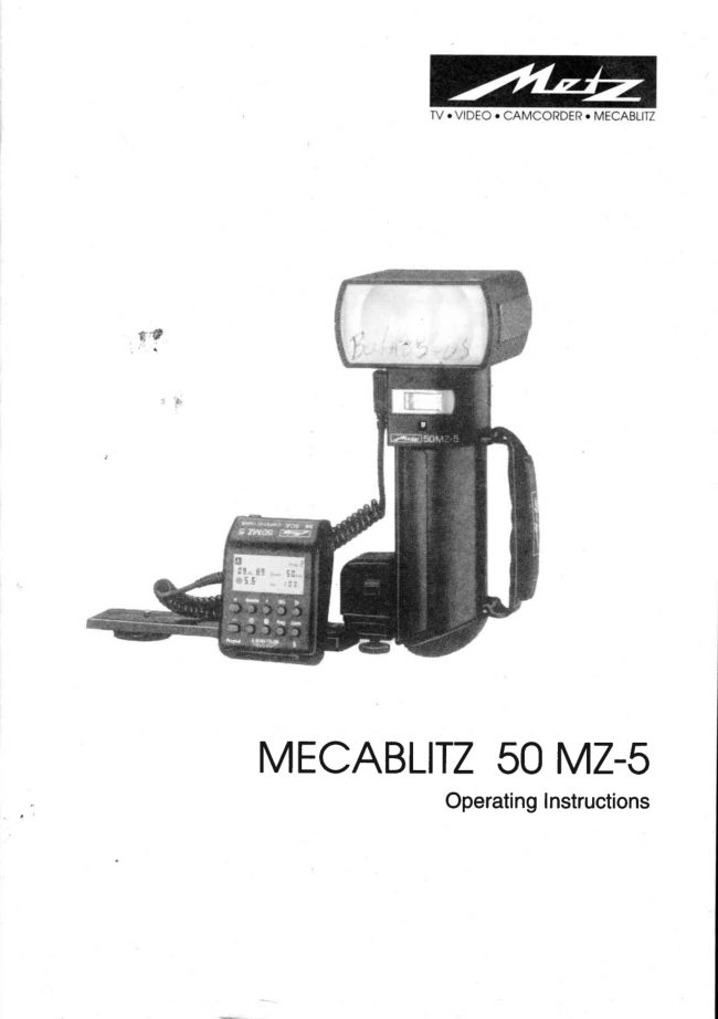
Metz Mecablitz 50 MZ-5 (one file B&W) User manual
User manual for Metz Mecablitz 50 MZ-5 (one file B&W). 54 pages in English. Read the original PDF, download or print a copy without registration.
54 pagesEnglish5.6 MB PDF

Loading your manual…Open PDF directly
Document details
- Brand
- Metz
- Model / document
- Metz Mecablitz 50 MZ-5 (one file B&W)
- Document type
- User manual
- Language
- English
- Pages
- 54
- File size
- 5.6 MB
- Category
- Film cameras
- Document date
- Not specified in catalog
Search available document text
Find a term, then jump to its page in the original PDF. Image-only pages may not be searchable; check the PDF for exact wording and diagrams.
Page 2 · Read text
www.orphancameras.com


 www.orphancameras.com


MECABLITZ50 MZ-s
               OperatingInstructions
View original page 2Page 5 · Read text
www.orphancameras.com


o NEVERfire a flash in the immediatevicinityof the eyes!
 Flashfired directlyin front of the eyesof a personor animalcan damagethe retina
 andleadto severevisualdisorders- evenblindness!
. Neveropenor short-circuitrechargeablebatteries!
. Donot exposebatteriesto excessiveheat,for instancesunshine,etc.!
r Neverthrowexhaustedbatterieson a fire!
. Donot exposethe flashgunto drippingandsplashingwater!
o Protectthe flashgunagainstexcessiveheatandhumidity!Donot storethe flashgunin
 the glovecompartmentof a car!
. Donot coverthe ventilationslotsand intakeopeningon the flashgun.
o The mecablitzis self-protectingagainstoverheatingby automaticallyextendingthe
 flash recyclingtime with serialflash shotsat full light outputand short recycling
 times.
o Neverplacematerialthatis imperviousto light in front of, or directlyon,the reflector
 screen.The reflectorscreenmust be perfectlycleanwhen a flash is fired. The high
 , energyof the flashlight will burnthe materialor damagethe reflectorscreenif this is
 not observed!
. NEVERdismantlethe flashgun!DANGER:'HIGHVOLTAGE!
 Thereareno componentsinsidethe flashgunthat canbe repairedby a layperson.
View original page 5
Page 6 · Read text
www.orphancameras.com
       z.Preparingtheflashgunfor use


                                                                                                          www.orphancameras.com


      ',i                           #'
Fig.1:Mountingthecomponents,andremovingthestandardbaseorscAadapter
2.1Attachingthecontrotunitandtheflashgunto thecamera
rhe controlunit cangntybemountedonthecamerawiththe301standardbase(5)or with
anSCA-300orSCA-3000adapter(SpecialAccessories)'
 --@  Atwaysswitchoff thecameraandthe flashgunbeforenountilq or removingffie
    nasigun.Thered-tightadapgrc(seeatsoch.7,p. 20)ot thescA3N System'as
     weltas ffie SCAsdana ni  nt  MulticonnectorscA m5 A, canonlybe usedif the
       g00D spaceris mountedbetweenthe adapterand the control unit'    scA
Pushthe controlunit,withattachedadapteror 301standardbase,intothe camela's
accessoryshoeandctampintopositionwitniheknurlednut(6).Thecontrolunitisfittedwith
the301standardbaseforsimpleflashsynchronization'
Mountinglheflashgun:
 o Fastenthecamerabracket(8)withthebracketscrew(7)to thecamera'stripodbush'
 o PresstheunlocKngcarcn(f q ontheNicadbattery,andturnthebatterycover(10)anti-
  clockwiseuntilthe1stlock-inpositionis reached'
 o lnserttheholderblockofthecamerabracketintotheguidinggrooveoftheflashgun'
 o Fastentheholderblockwiththelockingscrew(9)'
 . Turnthebatterycover(10)clockwiseuntitit isonceagainlocked'Therectangularprojection
  thencoverstheopeningoftheguidinggroove'
 Dismantlingthestandardbaseor theSGAadapter:
 1 pushthelockinglugupwardstowardsthecontrolunit'
 2 Removethestandardbaseor SGAadapter'


                                                                                                                                                                                                          J
View original page 6Page 7 · Read text
www.orphancameras.com
                                                I  "'-:1'':...''- =           ii.                      i::iiigljlii
                             $:':ff   [  1'          ;+i++t+r+tl'ii


Fig.4: Measuringmethodfor TTLmode
Perfectflashexposurescanbeshotin a simplemannerin theTTLmode.
Theexposurereadingsin TTLmodearemadebythesensorbuiltintothecamera(fig.4).This
sensormeasuresthelightreachingthefilmthroughthecameralens.Assoonasthefilmhas
beenexposedby the correctamountof lightan electroniccontrolcircuitwithinthe camera
transmitsa stopsignalto thecontrolunit,andtheflashis instantlycutout.
Theadvantageof thisflashmodeis thatallfactorsinfluencingtheexposureof thefilm(filters,
changeof apertureandfocallengthwith zoomlenses,extensionsfor close-ups,etc.)are
automaticallytakenintoaccount,
Themecablitz50 MZ-5offerstwoTTLflashmodes:theTTLModeandtheTTLEasyMode.
 6i   The TTLflashmode is onty possibtewith camerasthat feature this function. The
     control unit mustbe fitted with a correspondingSCAadapter (see ,,SCA3000
    System"  instructions and SCA survey  table)  for  this purpose.
    A film must be loadedin the camerato test the TTL"functions.
 6,  Exposurecorrectionsmay be necessarywith pronounceddifferencesin contrast,
      for instancedark objectsin snow (seech, 14,p.4l).
3.1TTLEasyflashmode(EM= EasyMode)
Thisis thesimplestwayto operatethemecablitzin TTLflashmode.All buttonsonthecontrol
                                                                 '* unitare locked,withthe exceptionof the LCDlight  eT andthe manualfiringbutton
  I tssl.
 InTTLEasy-ModewiththeSCA300adapter,thezoompositioniSconstantlyadjustedto 28 mm
 to ensurethatthesubjectis alwaysadequatelyilluminated
 InTTLEasy-ModewiththeSCA3000adapter,thezoomsettingis matchedto thefocallength
 of the lens,andthedistancerangeis indicateil,providedthatthecamerasuppliesthezoom
 information.

                               1 0
View original page 7Page 8 · Read text
www.orphancameras.com

                3. TTLflashmode


                                Zoomf Hrt
                              Ffr55


                                                                                                 . +    Remote  P    ISO       f
                 CCCOC
                                                                                     : . - * O P r o g . Z o o m


                                          MZ50_8b                       1
Fig.5: Adjustingprocedurefor TTLEasy-Mode
W  Werecommendthe TTLEasy-Modewhenusing an SCA300adapter.Distance
     indicationin the LGdisplayis not possiblein thismode.
Adjustingprocedurefor TTLEasy-Mode:
n Adjustthecameraaccordingto themanufacturer'soperatinginstructions.
r Fitthecontrolunit(2)to thecorrespondingSCAadapter,andmountonthecamera.
 . Switchontheflashgunwiththemainswitch(10).
1 Adjusttheoperatingmodeselector(28)to EM.


                               11
View original page 8Page 9 · Read text
www.orphancameras.com
                3. TTLflashmode


                                ,m   t      prog.X
                              *:Fl   zi,H 5il.'
                  S    ff   Fo  iflf

                                         +   Rsmotc P   ISO     f
                      C C C C C
                                                                                     : + O P r o g . Z o o m


                                                                                                                                                                                                          I'                         1
Fig.6: Adjustingprocedurefor TTLflashmode
Adiustingprocedurefor TTLflashmode:
 . Adjustthecameraaccordingto themanufacturer'soperatinginstructions.
 . Fitthecontrolunitto thecorrespondingSCAadapter,andmountonthecamera.
 . Switchontheflashgunwiththemainswitch(16).
 1 Adjusttheoperatingmodeselector(28)to TTL.
o *PressthelS0 button(30),andadjustthefilmspeedwiththe+ or - button(24).
 . *PresstheZoombutton(32),andadjustwiththe+ or - button(24)thezoomvaluethatwas
  selectedforthecamera'slens.
 . *Pressthe buttonO 1S+1,andusethe + or - button(24)to adjustthe apertureuntilthe
   subjectis locatedin the middlethirdof the indicateddistancerange.Setthe resulting
   apefturealsoonthecamera.
o lf requiredpressbuttonP (29),andadjustthepaftiallightoutputwiththe+ or - button(24)
   (forWinderModeseech.B,p. 25).
                                                                                        " Mustbeadditionallyadjusted0nsomecameras.
M  0n somecamerasthedatafor IS0andaperturearetransferredto thecontrolunit
    by wayof the SCA3000adapterandcannotbe changedmanually.


                               12
View original page 9Page 11 · Read text
www.orphancameras.com
                r4:,  : 0ffi.efiC'flA$h''mofiH


Fig.7: Measuringprocedurefor automaticflashmode
Intheautomaticflashmodethesensor(4)of thecontrolunitmeasuresthelightreflectedfrom
the subject.Theflashis cut off as soonas sufficientlighthasbeenemittedfor a correct
exposure.
In thismannerthereis no needto calculateandadjusta newapefturewhenthe distanceis
changed,providedthatthesubjectremainswithintheindicatedautomaticflashrange,
Thesensor(4)of thecontrolunitmustbedirectedat thesubject,regardlessof thedirectionat
whichthemainreflector(1)is pointing.Thesensorhasa measuringangleof approx.25o,and
it onlymeasuresthelightemittedbytheattachedflashgun.
Partiallightoutputlevelscanalsobeadjustedin automaticflashmode(seech.g.1,p. 26).
Betweensix andtwelveworkingaperturesare availablein the automaticflashmode,
dependingupontheadjustedlsOfilmspeed0able2 of theTechnicalData).
Adjustingprocedurefor automaticexposurecontrol:
. Adjustthecameraaccordingto themanufacturer'soperatinginstructions,
o Switchontheflashgunwiththemainswitch(16).
1 Adjusttheoperatingmodeselector(2S)to A.
o *Pressthe lS0 film speedbutton(30),andadjustthefilmspeedwiththe+ or - button(24).
'*PresstheZoombutton(32),andadjustwiththe+ or - button(24)thezoomvaluethat
 wasselectedforthecamera'slens.
o PressbuttonO 1S+;,andusethe+ or - button(24)to adjusttheapertureuntil thesubject
  is locatedin themiddlethirdof theindicateddistancerange.Settheresultingapefturealso
 onthecamera.
o lf requiredpressbuttonP (29),andadjustthepartiallightoutputwiththe+ or - button(24)
  (see ch' 9' p' 26)
                                                                       * Mustbeadditionatyadjustedonsomecameras.

                               1 4
View original page 11Page 12 · Read text
www.orphancameras.com


                 El.e..Y.Y ZJBH5 0"

                 ooooo+   Rcmotc P   FO   D
                                                                     *   O   Rrog zoom


Fig.8: Adjustingprncedurefor automaticflashmnde

 gg' Somecamerasautomaticallytransmit the IS0,apertureand zoom valuesto the
     control unit also in the auto flash modeit an SCA30M adapteris used.No
     settingshave to he adjustedon the control unit where this is the case.
ThepermissibledistancerangeandthecorreSpondingapertureappearontheLCdisplay.
 gg, Thesubject shouldbe located within the middle third of this distancerangeas
      this givesthe electroniccontrol sufficient scopetor compensationshould this be
     necessary.
Thereis a certainmeasureof overlapbetweentheindividualworkingapeftures.Asa resultof
thisoverlapit is alwayspossibleto placethesubjectwithinthemiddlethirdof therange,

 gg' CAUTI0Nwith zoom lenses!
    Due to their design they ean causea lossof light in the order of up to one f-stop.
     Furthermore,the effective aperture can also vary, dependingupon the adjusted
      focal length. This must be compensatedby manually correcting the aperture
      settingon the control unit!


                               1 5
View original page 12Page 13 · Read text
www.orphancameras.com

              5. Manualflashmode


Fig.9: Shotwith directflashlight
Inthismodetheflashgunwillemititsfullpower,providedthatpartiallightoutputhasnotbeen
adjusted.
Adaptationto the pictureshootingsituationis by settingthe correspondingapertureon the
camera.
A singlevaluefortheflash-to-subjectdistanceappearsontheLCdisplaywhilein manualflash
mode.
 lf the displayedvaluedoesnot coincidewith the actualdistance,thenthe apertureand/or
paftiallightoutputlevelhaveto bechangedaccordingly(seech.9.2,p.26).

Thedecisivepointsfor paftiallightoutputare:
 . Thedistanceto thesubject
 . Therequiredaperture
 . ThelS0filmspeed
 . Thezoomsettingof thereflector
 gg' Thefine scalingof the partial light output levelsensuresthat the flash-to-subject
     distancecan be adjustedin very small increments,
Adjustingprocedureforthemanualflashmode:
 .  Adjustthecameraaccordingto themanufacturer'soperatinginstructions.
 .  Switchontheflashgunwiththemainswitch(16).
 1 ROlusttheoperatingmodeselector(2S)to M.
 . *PressthelS0 button(30),andadjustthefilmspeedwiththe+ or - button(24).
 .  *PresstheZoombutton(32),andadjustwiththe + 0r - button(24)the zoomvaluethat
  wasselectedforthecamera'slens.

                               1 6
View original page 13Page 14 · Read text
www.orphancameras.com

               5. Manualffashmode


                 m       zffi  50rt
                        Oii     Fo tEE


Fig.10:Adjustingprocedureformanualflashmode
2 PressbuttonO (ga)
3WnileO isflashingusethe+ or- button(24)to adjusttheapertureinsucha mannerthat
 thesubjectis locatedinthemiddlethirdoftheindicateddistancerange.Settheresulting
  aperturealsoonthecamera.
 . lf required,pressbuttonP (29),andadjustthepartiallightoutputwiththe+ or- button
  (24)(seech.9, p.26).
 6,  Somecamerasautomaticallytransmittheaperture,lS0andzoomvaluesif an SCA
    3000adapteris used.ln sucha casethe apertureon the cameramustbe
    continuouslychangeduntil therequireddistanceis indicatedon theLCdisplayof
     the controlunit,
                                                                                                                 .                                                       Mustbeadditionallyadjustedonsomecameras.


                               1 7
View original page 14Page 15 · Read text
www.orphancameras.com
                6. Bouncedflash


Fig
Photosshotwithfullfrontalflashareeasilyrecognizedbytheirharsh,denseshadows.Thisis
oftenassociatedwitha sharpdropof lightfromtheforegroundto thebackground.
Thisphenomenoncanbeavoidedwithbouncedflashbecausethediffusedlightwill produce
a softanduniformrenditionof boththesubjectandthebackground.Forthispurposethemain
reflector(1)isturnedin sucha mannerthattheflashis bouncedoffa suitablereflectivesurface
(e.9.ceilingor wallsof a room).
Forthis reasonthe reflectorcan be turnedverticallyand horizontally.Theverticallock-in
positionsfor bouncedflashare:
 . 60",75"and90" (simplytiltthereflectorto therequiredangle)
Theheadcanbeswivelledhorizontallyby 270",andlocksintopositionat 90' and180'.
 6,  Thedistance valueson the LC display disappearas soon as the reflector is tilted
     upwardsor turnedhorizontally.Thisis becausethe spatial conditionsand degree
      of reflectiondo not allow the specificationof definite distances.
Whenswivellingthemainreflector(1) it is essentialto ensurethatit is turnedbya sufficiently
wideangleso thatdirectlightcanno longerfallon thesubject.Therefore,alwaysswivelthe
 reflectorto at leastthefirstlock-inposition.
Thediffusedlightbouncedbackfromthereflectivesurfacesresultsin a softilluminationof the
 subject.
Thereflectingsurfacemustbewhiteor havea neutralcolourandit mustnotbestructured(e.9.
woodenbeamsin the ceiling)as this couldcastshadows.Forcoloureffectsjust select
 reflectivesurfacesin therequiredcolour.
Useof thesecondaryreflector(11)is advantageousto avoiddisturbingdenseshadowswith
 bouncedflash,for instanceundertheeyesandnosewithportraits.


                               1 8
View original page 15Page 16 · Read text
www.orphancameras.com


                                                          .:::!:::.:::.:.:i:.:.::::::..:::::i:.:r.:::,::::::::::.::,:..::,:::::::.::,.::::..::::  :: .:',::'::::::':.r:::.'...,..:....:.,:i,.:.,:,:,,::::.::::,:::.:::.,:::,,i.::...:: ,. ,,.,,,:. :i
                           ,,..',..,'.,i.'r..'ri.'r,;'.,.':,.';'.:..,...t,..,..,.,':','.'.'..,.'.:',:':,.,....'.',,.'.'' tl-'i        : Boun,cedflash
                                                                                                                                                                                                                                                                                                         ::::Lt:lir::i


                                    - -.D.                            Zoom
             6 5.8   Fo tgg

            o+   Romoteo.oP   60o oE
          ooooc+   O    Prog. Zmm
                            A H t+tTTtAl
                         Turbook       \\\       //                 |
              O O        - M     O

Fig. 12:Bouncingthe ftashwithswitched-onsecondaryreflector
6.1Bouncedflashwithsecondaryreflectorswitchedon
Thesecondaryreflector(11)producesfrontalfill-inlightwhenbouncingtheflash.
 gg- The useof the secondaryreflector is only expedientwith bouncedflash. The
    secondaryreflector will only tlash when the main reflector hasbeen turnedor
       tilted.
Thesecondaryreflector(11)is switchedon or off withswitchGG (21).Symbolson the LC
displayindicatethatthesecondaryreflector(11)hasbeenswitchedon (fig.l2).
Whenthesecondaryreflectoris activated,90%ofthelightwillbeemittedbythemainreflector
(1),andapprox.10%by the secondaryreflector(11).Thequotedpercentagesmayvary
somewhatwhenflashwith partiallightoutputis adjusted,andthe secondaryreflector(11)
switchedon.Lightoutputcanbe reducedto 112or 114withswitch(21)whenthelightoutput
of thesecondaryreflector(11)is toohigh.
6.2Bouncedflashin automaticandTTLflashmodes
 It is advisableto checkpriorto exposurewhetherthelightissufficientfortheselectedaperture.
Pleasereferto ch.13.2,p. 34,forthecorrespondingprocedure.
6.3Bouncedflashin manualflashmode
Therequiredcameraaperturein the manuatflashmodeis bestestablishedwithan exposure
meter.0bservethefollowingruleof thumbif an exposuremeteris notavailable:
                         guidenumber    Cameraaperture=                                 light distancex 2
to establishthe guidevaluefor thef-stopthatcanthenbe variedby +1 f-stopfor the actual
exposure.

                               1 9
View original page 16Page 18 · Read text
#                                  www.orphancameras.com


                                                 i1


    Fig.13: Set-upfor theremotecontrolmode
    Definition:
         'remote    Here,        control'means cordlessfiring of additional(slave)flashguns.Thecontrotling
   masterflash(controller)attachedto thecameracontrolstheadditionalflashunits(slaves)with
   a startpulsein sucha mannerthatautomaticexposurecontrolin TTLflashmodeis extended
    to all slaveflashguns.
   TheMetzremotecontrolmodepermitsjoint,cordlessflashcontrolof severalotf-camera
   flashgunsof thetype40 MZ-2and50 MZ-s,
   Forthispurposealladditionalslaveunitsof thetype40 MZ-zmustbefittedwithanSCA3080
   slaveadapter(SpecialAccessories).Additionalslaveflashgunsof the type50 MZ-sdo not
    requiretheSCA3080slaveadapter.

   Forclose-upswitha wideaperturesettingandbrightambientlight,it is quitepossiblethatthe
    staftpulseof thecontrolunitcanbesufficientforcorrectexposureofthefilmwithoutrequiring
   anyadditionallightoutput,Theslaveunitsarethennotfired,or firingis delayed(ca.0.7sec.).
   Consequently,theywill onlyindicatetheiroperatingreadinessanddo notcontributeto the
   exposureof thefilm.
   Therearethreewaysto overcometheproblem:
   o Reducetheambientlight
   o Stopdowntheapefture(e.9.f/8 insteadof f/5.6)
   o Selecta filmwitha lowerlS0filmspeedrating

   Twoditferentaddressescanbeselectedonthecontrolunitsothattwo remotesystemsin the
   sameroomcannotinterferewith eachother.Theadjustedaddressesare automatically
    transferredto theslaveflashgunsaftera testflash.


                               21
                                                                                                                                                   /
View original page 18Page 19 · Read text
www.orphancameras.com

       7.1GordlessMetrTTtremotecontrol


                                         :                     zJS 50"


                                  HZ50-13
Fig.14:AdjustingprocedurefortheMeETTLremotecontrolmode
Adiustingprocedurefor theMetzTTLremotecontrolmode:
 . Adjustthecameraaccordingto the manufacturer'soperatinginstructions.
o Seta shuttersynchspeedof 1/60thsec.or sloweronthecamera.
 . Switchonthe masterflashattachedto thecamerawiththe mainswitch(16).
1 ROjusttheoperatingmodeselector(28)to TTL.
2 PresstheRemotebutton(221onthecontrolunitmountedonthecamera.Thedistance
  valuesontheLCdisplaydisappear.
3 Selectthecontrolleraddress(datatransferchannel)Co1 or Go2 withthe- or + button
  (241.
 . EquipthetlOMZ-2slaveflashgunswithan SCA3080slaveadapter;switchon withthe
  mainswitchandadjustto TTL.The40 MZ-2slaveflashgunshavenowbeenadjustedto
  slavemode.Switchonthe50 MZ-i slaveswiththe mainswitch.Awaitflashreadinessof
  allflashguns.
4 Pressthemanualfiringbutton(35)onthecontrolunitmountedonthecamera,andfirea
  testflashsothattheslaveis adjustedto thecontrolleraddress.
o Theslaveflashunitwillrespondwitha delayedflash,therebyindicatingthatit is readyfor
  operation.Allslaveunitssimultaneouslyacknowledgeoperatingreadinesswhenseveral
  slavesarebeingjointlyused.
   lf a slaveunitdoesnotrespond,thisindicatesthatthesensor(13)in theslave'shandledid
  notreceivea lightpulse.Turnthehandleof theflashgunsothatthesensor(13)canreceive
  thelightpulsefromthemasterflash.NowrepeatprocedureN0.4.A particularlyshort
  distancebetweenmasterflashandslavemayresultin over-modulationof thesensor.In
  thiscasewidenthedistanceandrepeatprocedureNo.4.


                            22
View original page 19Page 20 · Read text
www.orphancameras.com
            7.:l:il::i-iggd|6.5$...'M$lilTE..:,ferl|0tGG0n:tfG|:

                                                       controlleraddress1
           + *.*    ONI

                                                    controlleraddress2
                                       .6.lil.                                t


Fig.15:Displayfor operationwithslaveunits
A modellinglight(approx.4 sec.)canbetriggeredwiththemodellingflashbuttonMF(19)on
themasterflashsothattheoveralllightingconditionsin remotecontrolmodecanbeassessed.
All50 MZ-sslaveslikewiseemita modellinglight.
 6,   Thesecondaryreflectorcannotbeswitchedonin remotecontrolmode!
Gheckingandchangingthe slaveaddress:
TheCo1or Co2controlleraddress(datatransferchannel)is permanentlyadjustedaftera test
flashhasbeenfiredas describedin procedureNo.4. Theflashingflash-readinessdisplayon
the 50 MZ-sindicatesthe addressto whichthe slaveunit hasbeenadjusted.Controller
addressCo1hasbeenadjustedif theflash-readylight(18)on the handleflashesin a single
secondcycle(-        -); doubleflashingof theflash-readylight(18)in a singlesecondcycle
(-- -- -- --  --) indicatescontrolleraddressCo2.                                           .
Ghangingtheaddresssetting:
 . Switchofftheslaveunitfor at least5 seconds.
 . Switchontheslaveunit.
 . RepeattheproceduresNo.3 andNo.4 to reprogramtheslaveto a newaddress,

Theacknowledgementof flashreadinessin remotecontrolmodeis particularlyimportant.
Flashreadinesshasbeenreachedwhentheflash-readylight(18)on theslaveunit50 MZ-5
flashes.
Switchingoff theMetrTTLremotecontrolmode:
o PresstheRemotebuttononthecontrolunittwice,
o Switchofftheslaveforat least5 seconds.

                            23
View original page 20Page 21 · Read text
www.orphancameras.com


ln theMetzautomaticremotecontrolmodethemasterflashgunat thecameracontrolsthe
additionalflashguns(slaves)in sucha mannerthattheautoflashmodeis transferredto all
slaveunits.Exposureis controlledbythesensnr(4)of thecontrolunit.Toimplementthismode
all 40 MZ-2slaveflashgunsmustfirst be fittedwithan SCA3080slaveadapter(Special
Accessories)50MZ-stypeslaveflashgunsdonotrequirea slaveadapter.
TheMetzautomaticremotecontrolmodecan be used with system,standard,old
mechanicalandmedium-formatcameras,
Theonlypreconditionis that all camerasfeaturea synchcontacUsockeit,and are
equippedwitha 301standardbaseor SCAadapter.
Adiustingprocedurefor the Metzautomaticremotecontrolmode:
. Adjustthecamerato manualmodeas explainedin themanufacturer'soperating
  instructions.
o Seta shuttersynchspeedof 1/60thsec.or sloweronthecamera.
. Switchonthemasterflashgun(controller)withthemainswitch(16).A40MZ-2cannotbe
 usedas masterflashgunin conjunctionwith50 MZ-sflashguns.
. Adjusttheoperatingmodeselector(28)to A.
r PresstheRemotebutton(22) onthecontrolunit.ThedistancevaluesontheLCdisplay
 disappear.
o SelectthecontrolleraddressGo1 or Go2 withthe + button(24),
. Equipthe40 MZ-zslaveflashgunswithanSCA3080slaveadapter;switchonwiththe
 mainswitchandadjustto TTL.The40 MZ-zslaveflashgunshavenowbeenadjustedto
 slavemode.Separatethe50 MZ-5slavesfromthecontrolunit,andswitchonwiththe
 mainswitch.
o Pressthe manualfiringbutton(35)onthecontrolunit,andfirea testflash.
r Theslavewillrespondwitha delayedflash,therebyindicatingthatit is readyfor operation.
  Allslaveunitssimultaneouslyacknowledgeoperatingreadinesswhenseveralslavesare
 beingjointlyused.
   lf youfindthata slaveunitdoesnotrespond,thlsmayindicatethatthesensor(13)in the
  slave'shandledidnotreceivea lightpulse.Turnthehandleof theflashgunin sucha
 mannerthatthesensor(13)canreceivethelightpulsefromthemasterflash.Nowfire
 anothertestflash.A particularlyshortdistancebetweenmasterflashandslavecanresultin
 overmodulationof thesensor.ln thiscasewidenthedistanceandrepeatthetestflash.
Proceedas describedin ch.7.1to checkandchangethe slaveaddress,andto switchoff
the automaticremotemode.A modellinglight(approx.4 sec.)canbe triggeredwiththe
modellingflashbuttonMF(19)onthemasterflashgunsothattheoveralllightingconditionsin
remotecontrolmodecanbeassessed.All50 MZ-sslaveslikewiseemita modellinglight.


                            24
View original page 21Page 22 · Read text
www.orphancameras.com
                   .,.,,,,,':':i'c'                       ili.illd;;...l.ildl;u,.'..t...'..**....'...
:irrilin:::!i:ji  liilt::.:ti:)ta

Definition:
Thewindermodeinvolvesshootinga sequenceof picturesat a rate of severalframesper
second.Thewindermode usespartialtight outputlevels.Table3 of the TechnicalData             l
 indicateswhichpartiattight outputtevetis suitedfor a givenframefrequency(framesper
second= flashesper second).

8.1Usingthewinderfacilityin manualflashmode
Inthemanualmode,theexposuresaremadewitha fixedpartiallightoutputlevelselectedin
contormitywiththewinderdata(Table3 of TechnicalData).
8.2Usingthewinderfacilityin automaticandTTLflashmode
 ln thismodeit is possibleto ensurethata flashwill befiredwitheachexposureof a seriesof
 pictures.Forthis purposea partiallightoutputlevelcanbe adjustedin conformitywiththe
winderdata(Table3 of theTechnicalData).

 6'  ShoEthat require tesslight are automaticallycontrolledby the automaticor TTL
       light output systemand are, therefore,correctly exposed.
     Shotsthat require more light than the adjustedpartiat tight output tevel may be           t
     underexposed.


                             25
View original page 22Page 23 · Read text
www.orphancameras.com
                                        .fi$.fi.t...'ffi.                                                        fifi  ....rlff ..l.'.l.lllllulft':ll:':
Definition:
Paftialtightoutputlevelsaremanualtyadjustabtefractionsof fulttightoutput.
Therecyclingtimesareshofterwhenpartiallightoutputlevels(seeTable1 of theTechnical
Data)are adjustedinsteadof full flashpower.At the sametimethe guidenumberof the
flashgunis diminished,togetherwiththeflashto-subjectdistanceandflashrange,because
onlypartof theflashpoweris emitted.
6'   Partialtight output cannotbe adjustedin remotemodes.Themaximum possibte
     partial light output level is automaticallyadjustedin stroboscopicmode.Partial
      light output in conjunctionwith turbo'modeis not advisable.
9.1Partiallightoutputlevelsin automaticflashmode
Partiallightoutputmaybeadjustedin theautomodeto ensurethata flashis alwaystriggered
witheachserialshot(windermode).
Theactuallightoutputlevelfor a givenflashfrequencyandnumberof flashesis specifiedin
Table3 of theTechnicalData.
9.2Partiallightoutputlevelsin manualflashmode
ln somespecialsituationsit maybe necessaryto reducethe amountof lightemittedby the
flashgunbecausethe selectedflash-to-subjectdistancemaymakeit necessaryto adjustan
excessivelysmallapertureandtherebycreatean unwantedwidedepth-of-field.Thisproblem
canbeovercomebyusingthepartiallightoutputfunction.
Thepartiallightoutputlevelsareadjustablewithinverycloseincrements.ln thismannerthe
distancevalueof the flashguncanbe easilymatchedto the subjectdistance.Thisensures
professionalflashexposuresof difficultsubjects(largedifferencesin contrastand extreme
degreeof reflectivity)whereautomaticexposurecannotproduceoptimalresults.
9.3Macrophotography(close-ups)
Forclose-upsit is importantto ensurethata certainminimumlightingdistanceis maintained
to avoidoverexposure.Forexposureswithextremelyshortflash-to-subjectdistancesyouwill
bewelladvisedto workwithsmallpartiallightoutputlevelsin manualmode.
Flashduration
Theadjustablepartiallightoutputlevelsresultin differentflashdurations(seeTable1 of the
TechnicalData).Thespecifiedflashdurationsonlyapplyto singleflashesin manualmode.In
serialflash(winderor stroboscopicmode)thelastflashesmayhavea longerflashduration.In
the automaticandTTLmodesthe flashdurationcan be shorterif the automaticexposure
controlswitchesoff the flashat an earliermoment.To adjustthe flashdurationfollowthe
proceduredescribedin 9.2.
View original page 23Page 24 · Read text
www.orphancameras.com

      9.Workingwithpartiallightougutlevels

              M           nos.0
          o 5r
                                  +   Rcnobo a-oP   FO of
                                                                     *    O      lr"T     zooill


                                     M250-15
Fig. 16:Adjustingpartiallightoutputlevels
Adjustingprocedurefor flashwithpartiallightoutput:
 . Adjustthecameraaccordingtothemanufacturer'soperatinginstructions.
 r Switchontheflashgunwiththemainswitch(16).
1 Adjusttheoperatingmodeselector(28)toA,TTLorM.
 . * PressthelS0filmspeedbutton(30),andadjustthefilmspeedwiththe+ or- button
  (241.
o * PresstheZoombutton(32),andadjustwiththe+ or - button(24)thezoomvaluethat
 wasselectedforthecamera'slens.
2 PressbuttonO (g[).
3 Usethe+ or - button(24)to continuouslychangetheapertureonthecontrolunituntilthe
  requiredf-stopappearsontheLCdisplay.Nowadjustthisf-stopalsoonthecamera.
 gg' Somecamerasautomaticallytransmittfieaperfitre,IS0andzoomvaluesit an
   SCA1Un adapteris used.ln tfiis caseffie apertureon thecameramustbe
    continuouslychangeduntiltherequircdt-stopappears,on theLCdisplayof tfie
     controlunit.
4 PressthepartiallightoutputbuttonP (29).
5 Continuechangingthepartiallightoutputlevelwiththe+ or - button(24)untilthesubject
  is locatedinthemiddlethirdofthedisplayeddistancerange.
'The partiallightoutputlevelcanberesetbybrieflyadjustingtheoperatingmodeselector
  (28)to anothermode.

                                                             'Must                                                           beadditionallyadjustedonsomecameras.


                          27
View original page 24Page 25 · Read text
www.orphancameras.com

          10.Stroboscopicflashmode


Fig.17:Thestroboscopicmode
In this modeseveralflashexposurescan be madeon the sameframe.Thisis particularly
interestingfor motionstudiesandfor specialeffects(fig.17).
Thestroboscopicmodefiresseveralflashesat a ceftainflashfrequency.Consequently,this
functionis onlypossiblewitha paftiallightoutputlevelof maximum114or less.
Fora stroboscopicexposureit is possibleto selecta flashfrequency(flashespersecond)of
1...50Hzin 1Hzincrements,anda numberofflashesof 2...30in singleincrements.
Themaximumpossiblepartiallightoutputlevelin stroboscopicmodeis automaticallyadjusted
(seeTable3 of the TechnicalData).Thepartiallightoutputlevelcanbe set manuallyto a
minimumvalueof 11256to achieveshortflashdurations.TheLCdisplayindicatesthedistance
applicableto thesetparameters.Thedisplayeddistancevaluecanbe matchedto theactual
shootingdistancebyvaryingthef-stopor thepartiallightoutputlevel.Theapefturedisplayed
onthecontrolunitmustbe adjustedon thecamerawhenthe301standardbaseor an SGA
3f,0adapteris used.Whenthe SCA3000adapteris beingused,the controlunitwill
automaticallyacceptthe apertureseton the camera,providedthatthe camerasuppliesthe
requisiteinformation.Thedistancerangecanbeextendedbyusinga high-speedfilm.

M  Thesecondaryreflector cannotbe usedin stroboscopicmode!

Adjustingprocedurefor stroboscopicmode:
 . Adjustthecamerato manualmode,as explainedin themanufacturer'soperating
  instructions,andselecta matchingshutterspeed(seeTable4 of theTechnicalData).
 . Turnontheflashgunwiththemainswitch(16).
 . lf thefilmspeedhasnotyetbeensetonthecontrolunit:
   - Adjusttheoperatingmodeselector(28)to A.
View original page 25Related documents and language editions
From the M. Butkus archive. Original publisher and archive notices are retained.
Check the model and edition against your equipment.
PDF verified 2026-10-10.