Film cameras
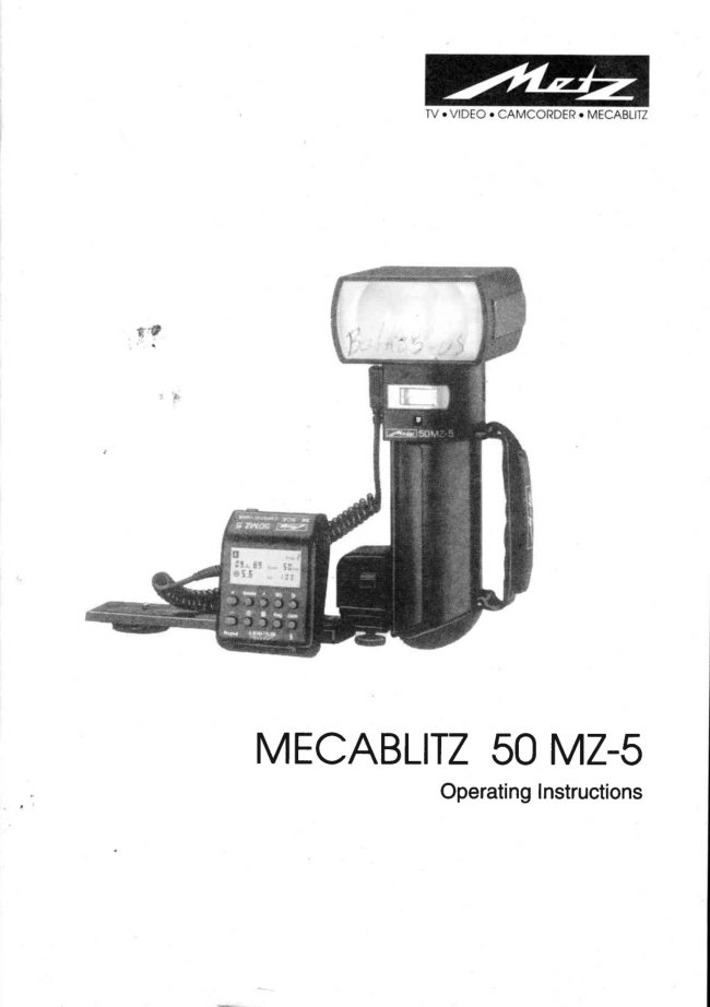
Metz Mecablitz 50 MZ-5 User manual
User manual for Metz Mecablitz 50 MZ-5. 58 pages. Read the original PDF, download or print a copy without registration.
58 pagesOriginal document5.2 MB PDF
Loading your manual…Open PDF directly
Document details
- Brand
- Metz
- Model / document
- Metz Mecablitz 50 MZ-5
- Document type
- User manual
- Language
- Check the original document
- Pages
- 58
- File size
- 5.2 MB
- Category
- Film cameras
- Document date
- Not specified in catalog
Search available document text
Find a term, then jump to its page in the original PDF. Image-only pages may not be searchable; check the PDF for exact wording and diagrams.
Page 6 · Read text
TheLGdisplay


                                         Programplace:
                                          0 = Worksurface
                                                 1-9= Userprograms
                Symbolforfill-inflash
                 (dependsoncameramodel)
  Symbolsforswitchedonsecondaryreflector
       Modedisplay

                                                                function
                                                   switchedon
      Distancein
      metersorfeet
       Aperture                                            AC0U$!Cexposure
                                                             control0N    Batterywarning
Red-eyereductionfacility
(dependsoncameramodel)

 Storageof valuesindicated
 onLCdisplay= ST0

      Callinga userprogram= RCL
     Numberof flashesin stroboscopemode= N
      Flashespersecondinstroboscopemode= f (Hz)
                            www.orphancameras.com
View original page 6Page 9 · Read text
Congratulationson purchasingthisMetzflashgun,andthankyoufor yourconfidencein Metz
equipment
It is onlynaturalthatyoushouldwantto useyourflashgunstraightaway.However,it will be
wellwofthyourwhjleto studythese0peratingInstructionsbeforehandto ensurethatyoucan
operatetheflashguneffectivelyandwithoutanyproblems.
Pleasealsoopenthe backcoverpagewith the illustrations.
Thisflashguncanbeusedwith:
o Allcameraswitha hotshoe
. Allcameraswithaccessoryshoewithouthot-shoecontact,andwitha synchronizingcable
. Systemcameras
Optimaladaptationto yourcamerais achievedby usingan SCAadapter.Theenclosed
SCA300/3000tablewillindicatetheadapteryourequireforyourparticularcameramodel,This
tablealsoindicatesthespecialflashfunctionsthatcanthenbecompletedbythegivensystem.
Briefsurveyof the operatingfunctions:
Configuration                  0peratingmodesoossible
o 50 MZ-5with301standardbase:   Automaticflashmode,ch.4,p. 14
                         Manualflashmode,ch.5, p. 16
                          Metzautomaticremotecontrol,ch.7.2,p.24
                             Stroboscopicmode,ch.10,p. 28
o 50 MZ-5withSCA300adapter:    Automaticflashmode,ch.4, p. 14
                        TTLflashmode*,ch.3, p. 10
                        TTLEasyMode*,ch.3.1,p. 10
                          Manualflashmode,ch.5, p. 16
                          MetzTTLremotemode*,ch.7.1, p.22
                          Metzautomaticremotemode,ch.7.2.p.24
                             Stroboscopicmode,ch.10,p. 28
                                                                                                             *lf                                                                           thecameraperformsthisfunction.
. 50 MZ-5withSCA3000adapter:   Automaticflashmode,ch.4, p. 14
                        TTLflashmode*,ch.3, p. 10                                                                '                        TTLEasyMode,ch.3.1, p. 10
                          Manualflashmode,ch.5, p. 16
                          MetzTTLremotemode,ch.7.1, p.22                       p24                   ffffl::il3'fJ;ilTTSlii\"
TheSCA3000adapteris themostconvenientlinkto yourcamera!ThelS0,zoomandaperture
dataaretransmitted,dependinguponthecameraconfiguration!
View original page 9Page 10 · Read text
|.ri.flxlli :1fiffiffiH.#1iftftHfi$frifrf                 ,
Generaloperatinginstructions
Thesubsequentinstructionsareof a generalnature.Theproceduresidentifiedbyrednumbers
mustbecompletedwhenusinga systemcamerain conjunctionwithan SCA3000adapter.
Allstepsidentifiedby rednumbersando arecompletedwiththe301standardbase.
                                  *Allstepsidentifiedwithan asteriskmustbeadditionallyadjusted,dependinguponthegiven
                                                                                                           ttypeof camera.
Whenmanualsettingsarenecessaryonthecontrolunitit is alwaysfirstnecessaryto pressthe
correspondingbuttonassignedto thegivenfunction.Thesymbolof theselectedfunctionwill
flashfor approx.5 seconds.Thevalueof thefunctionhasto be changedwiththe + buttons
duringthese5 seconds,othenruisetheexistingvaluewillberetained

.Example:Thezoomsettingis to be changed.
          1. Pressthe manualzoomcontrolbutton(32) - Zoom will flash for approx.5
          seconds.
        2.Aslongas zolm is flashingpressthe+ button(24)to raisethe value,e.g.from
         50 to 70. Zoomstopsflashingafter5 secondsand the changedvalueis stored.
N0TE:Theseinstructionsshow illustrations of the LCdisplay. Thedistancesindicatedin
these illustrationsare only examplesand not binding!
View original page 10Page 11 · Read text
ffgt.ffi
o NEVERfire a flashin the immediatevicinityof the eyes!
  Flashfireddirectlyin front of the eyesof a personor animalcan damagethe retina
 and leadto severevisualdisorders- evenblindness!
 . Neveropenor short-circuitrechargeablebatteries!
o Donot exposebatteriesto excessiveheat,for instancesunshine,etc.!
 . Neverthrowexhaustedbatterieson a fire!
                                                                                                                                                                  ' . Donot exposethe flashunit andchargerto drippingandsplashingwater!
o Protectthe flashgunagainstexcessiveheatandhumidity!Donot storethe flashgunin
  the glovecompartmentof a car!
. Donot couerthe ventilationslotsand intakeopeningon the flashgun.
 Heatbuild-upinsidethe flashgun(temperaturesexceeding40'C) automatically
 switcheson the built-infan to keepthe interiorof the flashguncool.
. As a resultof the high light energyof a seriesof flashesshotwith full light outputin
 quicksuccession,the ditfuserbecomesintenselyheatedin zoompositionsof 35 mm
 andless.In suchan eventthe flashrecyclingtime is automaticallyextendedin order
  to protectthe macablitzagainstoverheating!
o Neverplacematerialthat is imperviousto light in front of, or directlyon,the reflector
 screen.The reflectorscreenmust be perfectlycleanwhen a flash is fired. The high
 energyof theflashlightwill burnthe materialor damagethe retlectorscreenif this is
 not observed!
o NEVERdismantlethe flashgun!DANGER:HIGHV0LTAGE!
 Therearen0 componentsinsidethe flashgunthat canbe repairedby a layperson.
View original page 11Page 12 · Read text
2. Preparingtheflashgunfor use


Fig.l: Mountingtheconponents,andremovingthestandardbaseor SCAadapter
2.1Attachingthecontrolunitandtheflashgunto thecamera
Thecontrolunitcanonlybemountedonthecamerawiththe301standardbase(5)or with
anSCA-300orSCA-3000adapter(SpecialAccessories).
    Alwaysswitchotl fie camenandtheflashgunbeforemountingor removingffie6-
    flashgun.Thered-lightadapterc(seealsoch. 7,p;20) ot the SCA3N System,as
     wellas the SCA3ffi andthe TTLMulticonnectorSCA305A, canonlybe usedif the
   SCA300Dspaceris mountedbetweentfieadapterand thecontol unit
Pushthecontolunit,withattachedadapteror301standardbase,intothecamera'saccessoryshoe
andclampintopositionwiththeknurlednut(6).Inserttheplugof thecontrolunit'scableintothe
flashgun'shandle.Thecontrolunitisfittedwiththe301standardbaseforsimpleflashsynchronization.
Mountinglheflashgun:
o Fastenthecamerabracket(8)withthebracketscrew(7)tothecamera'stripodbush.
o Presstheunlockingcatch(14)ontheNicadbattery,andturnthebatterycover(10)anti-
  clockwiseuntilthe1stlock-inpositionis reached.
 . Inserttheholderblockofthecamerabracketintotheguidinggrooveoftheflashgun.
 . Fastentheholderblockwiththelockingscrew(9).
oTurnthebatterycover(10)clockwiseuntilit isonceagainlocked.Therectangularprojection
 thencoverstheopeningoftheguidinggroove.
Removingthecontrolunit,thestandardbaseor theSCAadapter:
@  Toremovethecontrolunit'scable,pressthegrayreleasebuttonagainstthe
    cable'splug whilepullingout thecable,
1 Pushthelockinglugupwardstowardsthecontrolunit.
2 RemovethestandardbaseorSCAadapter
View original page 12Page 13 · Read text
2. Preparingtheflashgunfor use


     batterycover


                                                                                        nrFboooP   EO
                                  ooo+ O p r c g
                                                            Ar$trnt


Fig.2a:Batterycover                     Fig.2b:Batterywarningindicator
 Attachingthestandardbaseor SCAadapter:
 . Takeholdofthebatterycover(fig.2a,onlywhenusingtheSCA3000adapter)inthemiddle
  andunclip.
 . PushintheSCAadapterorthe301standardbaseallthewayin.
Thecontrolunitis automaticallysynchronizedwiththecamerawhenit is insertedin the
camera'saccessoryshoe.
Synchronizationof cameraswithouthotshoeis possiblewitha synchcable(36-50,shortor
 36-51.1 m long,SpecialAccessories)inthesocketofthe301standardbase.
2.2Powersupplyandbatterywarningindicator
Theflashguncanonlybeoperatedwitha MetzNiCadBatteryPack50-40or thePowerPack
P50 (optionalaccessory).A chargerfortheMet batterypackis suppliedwiththeflashgun.
Thebatterywarninglightonlycomeson whentheBatteryPack50-40is beingused.The
operatinglight(17)inthehandlestartsflashingwhenthebatteryisexhausted,andthebattery
warninglightontheLCdisplaybecomesilluminated.
   Theflashingbatterysymbol(tig.2b)on tfieLCdisplayindicatesthat theNicad*ns,    batteryis almostexhausted.
t - ' S4entbatteriesmustnotbe throwninto the dustbin!Contributeto tfieprotection
    ot theenvironmentanddiscardspentbatteriesat theappropriatedisposalpointsl!
2.3Replacingandchargingthebattery
 r Switchofftheflashgunwiththemainswitch(16).
o Presstheunlockingcatch(14)ontheNicadbattery;turnthebatterycover(10)by45'anti-
 clockwiseuntilit becomesaudiblydisengagedatthe2ndlock-inposition,andremove.
View original page 13Page 14 · Read text
2. Preparingthetlashgunfor use


Fig.3: Unlockingandinseftingthebattery
o ConnectthechargertothechargingsocketoftheNiCadbattery,andthenplugintothemains.
  - Thecharger'stimerisswitchedonwhenthedeviceis pluggedintothemains.
  - TheredLEDremainsilluminatedallthewhilethebatteryisbeingcharged.
  - Afterapprox.6 hoursthechargerisswitchedovertotricklecharging.
  - A flashingredLED(4sec."0N",20sec."0FF")indicatesthatthebatteryisintrickle
   chargemodeandis readyforoperation.
 . Turnthebatterycover(10)anti-clockwiseuntilthe2ndlock-inpositionisreachedbeforethe
 batteryis returnedto thehandle.
o Forinsertionthebattery'schargingsocketmustbeinsidetheextensionofthealuminiumrail
 ofthehandle.
o Afterinsertionturnthebatterycoverclockwiseandlockin position.
Toidentifyan exhaustedbattery:Turnthe batterycoverclockwiseuntilthestoppointis
reached.
Toidentifya newlychargedbattery:Turnthebatterycoveranti-clockwiseuntilthestoppoint
is reached.
2.4Switchingtheflashgun0NandOFF
Theflashgunis switchedon withthemainswitch
(16).Theflashgunis permanentlyon in theOil
position,andtheoperatinglight(14 shines.Push
themainswitch(16)tothelowerpositionto switch
off.
View original page 14
Page 15 · Read text
Fig.4: Measuringmethodfor TTLmode
Perfectflashexposurescanbeshotin a simplemannerin theTTLmode.
Theexposurereadingsin TTLmodearemadebythesensorbuiltintothecamera(fig.4).This
sensormeasuresthelightreachingthefilmthroughthecameralens.As soonasthefilmhas
beenexposedby the correctamountof lightan electroniccontrolcircuitwithinthe camera
transmitsa stopsignalto thecontrolunit,andtheflashis instantlycutout.
Theadvantageof thisflashmodeis thatallfactorsinfluencingtheexposureof thefilm(filters,
changeof apertureandfocallengthwith zoomlenses,extensionsfor close-ups,etc.)are
automaticallytakenintoaccount.
Themecablitz50 MZ-sofferstwoTTLflashmodes:theTTLModeandtheTTLEasyMode.
    TheTTLflash modeis only possiblewith camerasthat feature this function. TheI€
     control unit must be tifted with a correspondingSCAadapter(see,,SGA3000
    System" instructionsand SGAsurueytable) for this purpose.
   A film must be loadedin the camerato test the TTLfunctions.
    Exposurecorrectionsmay be necessarywith pronounceddifferencesin contrast,@
      for instancedark objectsin snow (seech. 14,p. 4l).
3.1TTLEasyflashmode(EM- EasyMode)
Thisis thesimplestwayto operatethemecablitzin TTLflashmode.All buttonsonthecontrol
                                             -.O;unitare locked,with the exceptionof the LCDlight   (ZZ)andthe manualfiringbutton
 I tgsl.
InTTLEasy-ModewiththeSCA300adapter,thezoompositionis constantlyadjustedto 28 mmto
ensurethatthesubjectis alwaysadequatelyilluminated.
ln TTLEasy-ModewiththeSCA3000adapter,thezoomsettingis matchedto thefocallengthof the
lens,andthedistancerangeis indicated,providedthatthecamerasuppliesthezoominformation.

                               1 0
View original page 15Page 16 · Read text
3. TTLflashmode


                              zoomPE""
                       ERSY
                                                          r
                                                                           a\
                                                                                               Zooil^
                                                                                  I


Fig.5:Adjustingprocedurefor TTLEasy-Mode
 Je;, WerecommendtheTTLEasy-MNewhenusingan SCA300adapter.Distance
     indicationin ffieLCdisplayis not possiblein thismode.
Adjustingprocedurefor TTLEasy-Mode:
 . Adjustthecameraaccordingtothemanufacturer'soperatinginstructions.
o Fitthecontrolunit(2)tothecorrespondingSCAadapter,andmountonthecamera.
o Switchontheflashgunwiththemainswitch(16).
1 Adjusttheoperatingmodeselector(2S)to EM.


                               1 1
View original page 16Page 17 · Read text
3. TTLflashmode


                                      nos0
                       z#H50'-
                                rso i00

                 ooooo+     R-|Fi.   P   FO         f
                                                                          : + O P r o o z o i l


                                               1
Fig.6:Adjustingprocedurefor TTLflashmode
Adjustingprocedurefor TTLflashmode:
 . Adjustthecameraaccordingtothemanufacturer'soperatinginstructions.
 r FitthecontrolunittothecorrespondingSCAadapter,andmountonthecamera'
o Switchontheflashgunwiththemainswitch(16).
1 Adjusttheoperatingmodeselector(28)to TTL.
 . *PressthelS0button(30),andadjustthefilmspeedwiththe+ or - button(24).
 . "PresstheZoombutton(32),andadjustwiththe+ or- button(24)thezoomvaluethatwas
  selectedforthecamera'slens.
o *PressthebuttonO (34),andusethe+ or - button(24)to adjusttheapertureuntilthe
   subjectis locatedin themiddlethirdof theindicateddistancerange.Settheresulting
   aperturealsoonthecamera.
 .  lf requiredpressbuttonP (29),andadjustthepartiallightoutputwiththe+ or - button(24)
   (forWinderModeseech.8, p.25).
                                                                                                                                                                     '                                                          Muslbeadditionallyadiustedon somecameras.
B  Onsomecamerasthedatafor lS0andaperfureare transfenedto thecontol unit
    by wayof fie SCA3il)0 adapterandcannotbe changedmanually.


                            12
View original page 17Page 19 · Read text
4. Automaticflashmode


Fig.7:Measuringprocedureforautomaticflashmode
Intheautomaticflashmodethesensor(4)ofthecontrolunitmeasuresthelightreflectedfrom
thesubject.Theflashis cutoff as s00nas sufficientlighthasbeenemittedfor a correct
ex00sure.
Inthismannerthereis noneedto calculateandadjusta newaperturewhenthedistanceis
changed,providedthatthesubjectremainswithintheindicatedautomaticflashrange.
Thesensor(4)ofthecontrolunitmustbedirectedatthesubject,regardlessofthedirectionat
whichthemainreflector(1)ispointing.Thesensorhasa measuringangleofapprox.25',and
 it onlymeasuresthelightemittedbytheattachedflashgun.
Partiallightoutputlevelscanalsobeadjustedinautomaticflashmode(seech.9.1,p.26).
Betweensixandtwelveworkingaperturesareavailablein theautomaticflashmode,
dependingupontheadjustedlS0filmspeedffable2 oftheTechnicalData).
Adjustingprocedurefor automaticexposurecontrol:
 . Adjustthecameraaccordingtothemanufacturer'soperatinginstructions.
o Switchontheflashgunwiththemainswitch(16).
1 Adjusttheoperatingmodeselector(28)toA.
o *PressthelS0filmspeedbutton(30),andadjustthefilmspeedwiththe+ or- button(24).
 . "PresstheZoombutton(32),andadjustwiththe+ or - button(24)thezoomvaluethat
 wasselectedforthecamera'slens.
o PressbuttonS (34),andusethe+ or- button(24)to adjusttheapertureuntilthesubject
  islocatedinthemiddlethirdoftheindicateddistancerange.Settheresultingaperturealso
 onthecamera.
 . lf requiredpressbuttonP (29),andadjustthepartiallightoutputwiththe+ or- button(24)
  (seech.9,p.26)
                                                                                                                                                                      ' Mustbe additionallyadjustedon somecameras.

                               1 4
View original page 19Page 20 · Read text
4.Automaticflashmode

                                              )            nos0
                                il.'r..{.Yz$H 50"

                 ooooo+   R F t .   P    F O        f
                                                              - + O p r o $ z o o n


Fig.8:Adjustingprocedureforautomaticflashmode
   SomecamerasautomaticallytransmitthelS0,apertureandzoomvaluesto the*,
     controlunit alsoin theautoflashmodeit an SCAlilfi  adapteris used.No
     settingshaveto be adjustedon thecontrolunit wherethisis thecase.
ThepermissibledistancerangeandthecorrespondingapertureappearontheLCdisplay.
ng. Thesubiectshouldbe locatedwithinthemiddlethirdof thisdistancennge as
     this givestheelectroniccontrolsutficientscopefor compensationshoutdthisbe
    necessary.
Thereisa certainmeasureofoverlapbetweentheindividualworkingapertures.Asa resultof
thisoverlapit isalwayspossibleto placethesubjectwithinthemiddlethirdoftherange.
@ CAUTIONwithzoomlenses!
   Dueto theirdesigntheycan causea lossof light in theorderof up to onef-stop.
    Furthermore,theetfectiveapefturecanalsovary,dependingupontheadjusted
    tocallength.fhis mustbe compensatedby manuallyconectingtheaperture
     seftingon thecontrolunit!


                               1 5
View original page 20Page 21 · Read text
5. Manualflashmode


Fig.9: Shotwithdirectflashlight
Inthismodetheflashgunwillemititsfullpower,providedthatpartiallightoutputhasnotbeen
adjusted.
Adaptationto the pictureshootingsituationis by settingthe correspondingapeftureon the
camera.
A singlevaluefortheflash-to-subjectdistanceappearsontheLCdisplaywhilein manualflash
mode.
 lf the displayedvaluedoesnot coincidewiththe actualdistance,thenthe apertureand/or
 paftiallightoutputlevelhaveto bechangedaccordingly(seech.9.2,p. 26).

Thedecisivepointsfor partiallightoutputare:
 . Thedistanceto thesubject
 . Therequiredaperture
 . ThelS0filmspeed
 . Thezoomsettingof thereflector
M  Thefine scatingof the partial tight output levelsensuresthat the flash-to'subiect
     distancecan be adiustedin verysmall increments.


                               1 6
View original page 21Page 22 · Read text
5. Manualflashmode

                                               )             eros.E
                m      z#|f, 5 0"'
                  S   li    Eo t00

                                        +   RcmotcooocP   FO   D
                       +o


Fig.l0:Adjustingprocedurero,*uri,ititrrn*oa,
Adjustingprocedurefor themanualflashmode:
 . Adjustthecameraaccordingtothemanufacturer'soperatinginstructions.
o Switchontheflashgunwiththemainswitch(16).
1 nOlusttheoperatingmodeselector(2S)to M.
o *PressthelS0button(30),andadjustthefilmspeedwiththe+ or- button(24).
o *PresstheZoombutton(32),andadjustwiththe+ or - button(24)thezoomvaluethat
  wasselectedforthecamera'slens.
2 PressbuttonO (A+)
3 Changetheapertureontheflashgunwiththe+ 0r- button(24)sothattherequired
  distanceis indicatedontheLCdisplay.Adjustthisaperturevaluealsoonthecamera.
 . lf required,pressbuttonP (29),andadjustthepartiallightoutputwiththe+ or- button
  (24)(seech.9, p.26).
   Somecamerasautomaticallytransmittheaperture,lS0andzoomvaluesit an SCA6,
    3000adapteris used.ln sucha case the apertureon the cameramustbe
    continuouslychangeduntil therequireddistanceis indicatedon theLCdisplayot
    thecontrolunit.
                                                                                              -                                                       Mustbeadditionallyadjustedonsomecameras.


                               1 7
View original page 22Page 23 · Read text
6. Bouncedflash


Fig. 11:Bouncedflash(Thephotowasshotwiththeflashbouncedoff theright-handwall)
Photosshotwithfullfrontalflashareeasilyrecognizedbytheirharsh,denseshadows.Thisis
oftenassociatedwitha sharpdropof lightfromtheforegroundto thebackground.
Thisphenomenoncanbeavoidedwithbouncedflashbecausethediffusedlightwillproduce
a softanduniformrenditionof boththesubjectandthebackground.Forthispurposethemain
reflector(1)isturnedin sucha mannerthattheflashis bouncedoffa suitablereflectivesurface
(e.9.ceilingor wallsof a room).
Forthis reasonthe reflectorcan be turnedverticallyand horizontally.Theverticallock-in
positionsfor bouncedflashare:
 . 60",75"and90" (simplytiltthereflectorto therequiredangle)
Theheadcanbeswivelledhorizontallyby270",andlocksintopositionat90'and180".
6,  Thedistance valueson the LC display disappearas soon as the reflector is tilted
    upwardsor turned horizontally.Thisis becausethe spatial conditionsand degree
     of reflectiondo not allow the specificationof definite distances.

Whenswivellingthemainreflector(1) it is essentialto ensurethatit is turnedbya sufficiently
wideangleso thatdirectlightcanno longerfallon thesubject.Therefore,alwaysswivelthe
reflectortoat leastthefirstlock-inposition.
Thediffusedlightbouncedbackfromthereflectivesurfacesresultsin a softilluminationof the
subject.
Thereflectingsurfacemustbewhiteor havea neutralcolourandit mustnotbestructured(e.9.
woodenbeamsin the ceiling)as this couldcastshadows.Forcoloureffectsjust select
 reflectivesurfacesin therequiredcolour.
Useof thesecondaryreflector(11)is advantageousto avoiddisturbingdenseshadowswith
bouncedflash,for instanceundertheeyesandnosewithportraits.

                               1 8
View original page 23Page 24 · Read text
6:t:ii.:iB06*'gU..:::,f|il$:H


                                   -  --S.,  -  -                          Zoom
              S5.fi   Fo  ifI


                                           *    Remote  P    ISO       f
             C O O C C
                                             *   O    Prog. Zoom
             C O C C C
                                A M '''  TTLEM
                                          o*.       \\\         //
                <>o       t--Tit-"]  O

Fig. 12:Bouncingtheflashwithswitched-onsecondaryreflector
6.1Bouncedflashwithsecondaryreflectorswitchedon
Thesecondaryreflector(11)providesfrontalfill-inlightin incrementsof 1l4,112and1 with
bouncedflash.
6,  Theuse of the secondaryreflector is only expedientwith bouncedflash. The
    secondaryreflector will only flash when the main reflector hasbeen turnedor
      tilted.
Thesecondaryreflector(11)is switchedon or off withswitchCG (21).Symbolson the LC
displayindicatethatthesecondaryreflector(11)hasbeenswitchedon(fig.12).
Whenthesecondaryreflectoris activated,90%of thelightwillbeemittedbythemainreflector
(1),andapprox.10%by the secondaryreflector(11).Thequotedpercentagesmayvary
somewhatwhenflashwith partiallightoutputis adjusted,andthe secondaryreflector(11)
switchedon.LightoutputcanbereducedIo 112or 114with_switch(21)whenthelightoutput
of thesecondaryreflector(11)is toohigh.
6.2Bouncedflashin automaticandTTLflashmodes
 It isadvisableto checkpriorto exposurewhetherthelightis sufficientfortheselectedapefture.
Pleasereferto ch.13.2,p. 34,forthecorrespondingprocedure.
6.3Bouncedflashin manualflashmode
Therequiredcameraapefturein the manualflashmodeis bestestablishedwithan exposure
meter.Observethefollowingruleof thumbif anexposuremeteris notavailable:
                         guilenumber    cameraaperture=                              lightdistancex 2
to establishtheguidevaluefor thef-stopthatcanthenbe variedby +1 f-stopfor theactual
exposure.
                               1 9
View original page 24Page 26 · Read text
7. Gordlessremotecontrolmode


Fig.13:Set-upfor theremotecontrolmode
 Definition:
      'remoteHere,        control'meanscordlessfiring of additional(slave)flashguns.Thecontrolling
masterflash(controlle|attachedto thecameracontrolstheadditionalflash units(slaves)with
a startpulsein sucha mannerthatautomaticexposurecontrolin TTLflashmodeis extended
 to all slaveflashguns.
TheMetzremotecontrolmodepermitsjoint,cordlessflashcontrolof severaloff-camera
flashgunsof thetype40 MZ. . and50 MZ-s.
Forthispurposealladditionalslaveunitsof thetype40 MZ. . mustbefittedwithanSCA3080
slaveadapter(SpecialAccessories).Additionalslaveflashgunsof the type50 MZ-sdo not
requiretheSCA3080slaveadapter.
    ThemecablitzMZ 50-5can be usedas a slave when the plug of the control unit isW
     disconnected.
Forclose-upswitha wideaperturesettingandbrightambientlight,it is quitepossiblethatthe
startpulseofthecontrolunitcanbesufficientforcorrectexposureofthefilmwithoutrequiring
anyadditionallightoutput.Theslaveunitsarethennotfired,or firingis delayed(ca.0.7sec.).
Consequently,theywill onlyindicatetheiroperatingreadinessanddo notcontributeto the
exposureof thefilm.
Therearethreewaysto overcometheproblem:
 . Reducetheambientlight
o StoFdowntheaperture(e.9.f/8 insteadof f/5.6)
 . Selecta filmwitha lowerlS0filmspeedrating
Twodifferentaddressescanbeselectedonthecontrolunitsothattworemotesystemsin the
samer00mcannotinterferewith eachother.Theadjustedaddressesare automatically
transferredto theslaveflashgunsaftera testflash.

                               21
View original page 26Page 27 · Read text
7.1CordlessMetrTTLremotecontrol


                                            rrog.0
                   z#H50"


                               +   Rcmotc P   FO   D


Fig. 14:Adjustingprocedurefor theMeE TTLremotecontrolmode
Adiustingprocedurefor theMetzTTLremotecontrolmode:
 . Adjustthecameraaccordingto the manufacturer'soperatinginstructions.
o Seta shuttersynchspeedof 1/60thsec.0r sloweronthecamera.
o Switchonthe masterflashattachedto thecamerawiththe mainswitch(16).
 l ROlusttheoperatingmodeselector(28)to TTL.
2PresstheRemotebutton(221onthecontrolunitmountedonthecamera.Thedistance
  valuesontheLCdisplaydisappear.
3Selectthecontrolleraddress(datatransferchannel)Go1 or Go2 withthe- or + button
  (241.
 . EquipthetlOMZ. . slaveflashgunswithan SCA3080slaveadapter;switchon withthe
  mainswitchandadjustto TTL.The40 MZ. . slaveflashgunshavenowbeenadjustedto
  slavemode.Switchonthe50 MZ-i slaveswiththe mainswitch.Thezoompositionof the
  mainreflectorcanbeadjustedto 4 settings,withswitchGG: "0" = 28 mm,114= 35 mm,
  112- 50 mmand1 = 85 mm.Awaitflashreadinessof allflashguns.
4Pressthemanualfiringbutton(35)onthecontrolunitmountedonthecamera,andfirea
  testflashsothattheslaveis adjustedto thecontrolleraddress.
 . Theslaveflashunitwillrespondwitha delayedflash,therebyindicatingthatit is readyforoperation.All
  slaveunitssimultaneouslyacknowledgeoperatingreadinesswhenseveralslavesarebeingjointlyused,
   lf a slaveunitdoesnotrespond,thisindicatesthatthesensor(13)in theslave'shandledid
  notreceivea lightpulse.Turnthehandleof theflashgunsothatthesensor(13)canreceive
  thelightpulsefromthemasterflash.NowrepeatprocedureN0.4.A particularlyshort
  distancebetweenmasterflashandslavemaycausethesensor(4)to interrupttheemission
  of lightbeforetheinformationhasreachedtheslave.Inthiscasewidenthedistance
  betweencontrolunitandslave,or seta largerf-number,andrepeatprocedureNo.4.
View original page 27Page 28 · Read text
7.1GordlessMeETTLrorrotecontrol

                                                       controlleraddress1


Fig. 15:Displayfor operationwithslaveunits
A modellinglight(approx.4 sec.)istriggeredwiththeML(19)button(modellinglight)toassess
the overalllightingsituationin remotecontrolmode.All 50 MZ-5slavesalsogeneratea
modellinglight(seeSection13.9,page40).
6-  Thesecondaryreflector and/or partial light output mustnot be switched on in
    remotecontrol mode! TheflashingsymbolsGG indicate the inadmissible
    secondaryreflector setting. Partial light output levelscannotbe adjusted,
Checkingandchangingthe slaveaddress:
TheCol or Co2controlleraddress(datatransferchannel)is permanentlyadjustedaftera test
flashhasbeenfiredas describedin procedureNo.4. Theflashingflash-readinessdisplayon
the 50 MZ-5indicatesthe addressto whichthe slaveunithasbeenadjusted.Controller
addressCo1hasbeenadjustedif theflash-readylight(18)onthehandleflashesin a single
secondcycle(-       -);doubleflashingof theflash-readylight(18)in a singlesecondcycle
 (-- -- -- --  --) indicatescontrolleraddressCo2.
Changingtheaddresssetting:
 . Switchofftheslaveunitfor at least5 seconds.
 . Switchontheslaveunit.
 . RepeattheproceduresNo.3 andNo.4 to reprogramtheslaveto a newaddress.
Theacknowledgementof flashreadinessin remotecontrolmodeis particularlyimportant.
Flashreadinesshasbeenreachedwhentheflash-readylight(18)on theslaveunit50 MZ-s
flashes.
Switchingoff theMetzTTLremotecontrolmode:
 . PresstheRemotebuttononthecontrolunittwice.
 . Switchofftheslavefor at least5 seconds.

                               23
View original page 28Page 29 · Read text
7.2CordlessMetrautomaticremotecontrolmode

ln the Metzautomaticremotecontrolmodethe masterflashgunat the cameracontrolsthe
additionalflashguns(slaves)in sucha mannerthat the auto flashmodeis transferredto all
slaveunits.Exposureis controlledby thesensnr(4)of thecontrolunit. Toimplementthismode
all 40 MZ . . slaveflashgunsmust first be fitted with an SCA3080 slaveadapter(Special
Accessories).50 MZ-s typeslaveflashgunsdo not requirea slaveadapter.
The Metz automatic remote control mode can be used with system, standard, old
mechanicaland medium-formatcameras.
The only preconditionis that all camerasfeature a synch contacUsocket,and are
equippedwith a 301standardhase or SGAadapter.
Adjustingprocedurefor theMetzautomaticremotecontrolmode:
. Adjustthecamerato manualmodeasexplainedin themanufacturer'soperating
  instructions.
o Seta shuttersynchspeedof 1/60thsec.0r sloweronthecamera.
. Switchonthemasterflashgun(controller)withthemainswitch(16).A 40 MZ. . cannotbe
 usedas masterflashgunin conjunctionwith50 MZ-sflashguns.
. Adjusttheoperatingmodeselector(28)to A.
. PresstheRemotebutton(221onthecontrolunit.ThedistancevaluesontheLCdisplay
 disappear.
. SelectthecontrolleraddressGo1 or Co2 withthe+ button(24).
. Equipthe40 MZ. . slaveflashgunswithan SCA3080slaveadapter;switchonwiththe
 mainswitchandadjustto TTL.The40 MZ. . slaveflashgunshavenowbeenadjustedto
 slavemode.Separatethe50 MZ-sslavesfromthecontrolunit,andswitchonwiththe
 mainswitch.Thez00mpositionof themainreflectorcanbeadjustedto 4 settings,with
 switchGG: "0" = 28 mffi,114- 35 mm,112- 50 mmand1 = 85 mm.
o Pressthemanualfiringbutton(35)onthecontrolunit,andfirea testflash.
. Theslavewillrespondwitha delayedflash,therebyindicatingthatit is readyforoperation.
  Allslaveunitssimultaneouslyacknowledgeoperatingreadinesswhenseveralslavesare
 beingjointlyused.
   lf youfindthata slaveunitdoesnotrespond,thismayindicatethatthesensor(13)in the
 slave'shandledid not receivea lightpulse.Turnthe handleof the flashgunin sucha
 mannerthatthe sensor(13)can receivethe lightpulsefromthe masterflash.Nowfire
 anothertestflash.A particularlyshortdistancebetweenmasterflashandslavemaycause
 the sensor(4) to interruptthe emissionof lightbeforethe informationhasreachedthe
  slave.In this casewidenthe distancebetweencontrolunitandslave,or set a largerf-
 number,andrepeatprocedureNo.4.
Proceedas describedin ch.7.1to checkandchangethe slaveaddress,andto switchotf
the automaticremotemode.A modellinglight(approx.4 sec.)can be triggeredwiththe
modellinglightbuttonML(19)onthemasterflashgunsothattheoveralllightingconditionsin
remotecontrolmodecanbeassessed.All50 MZ-sslaveslikewiseemita modellinglight.

                               24
View original page 29Related documents and language editions

From the M. Butkus archive. Original publisher and archive notices are retained.
Check the model and edition against your equipment.
PDF verified 2026-10-10.