Flashes & lighting
Minolta Reflected light attachment for Flash/AutoMeter User manual
User manual for Minolta Reflected light attachment for Flash/AutoMeter. 1 pages in English. Read the original PDF, download or print a copy without registration.
1 pagesEnglish1.2 MB PDF
Loading your manual…Open PDF directly
Document details
- Brand
- Minolta
- Model / document
- Minolta Reflected light attachment for Flash/AutoMeter
- Document type
- User manual
- Language
- English
- Pages
- 1
- File size
- 1.2 MB
- Category
- Flashes & lighting
- Document date
- Not specified in catalog
Search available document text
Find a term, then jump to its page in the original PDF. Image-only pages may not be searchable; check the PDF for exact wording and diagrams.
Page 1 · Read text
MINOLTA

MARTE FAL bE, SELON EDAD ATSMET SEAMS. (IER 5 MOM)

anOA

1, ABH AT TOSI €, RETHMIC SSE CLT RATT.
2 RNHRT 2) FA OME E PHABMRCS DU TEDC A, KEVHMICALS SE COLMA ITT.
OMATERS, BERT) F4>KE RM BACELET,

mEOtA

BAK ELONES ET, RMART I FAL h eMC ST,
A SOLED SIE? Sy FA EBERT T,
3.MIEXS-PUTMELET,

[99 94 24—S-VAVAM + 4— bx — 3 —IVEANFANOWS)
moe RMS ERIM) ETE ET.

(79 74a%-3-10H8)

UDO RR ENETS, +3EVOMEX LETH. \/ REOFSEVOMMRE REE, ER
(SRA NAMES, 6 BL FIGLT MRL ET.

[4-he-9-1088)
HR OD & REE (i

Ste ghLT MEL ST.

Der Retlexlicht-Aufsatz wird zur Belichtungsmessung verwandt, wenn man die Belichtung
durch Messen des reflektierten Lichts ermitteln mdchte. Der Aufsatz verfigt Uber einen Einfalls
Winkel von ca. 40°, was etwa dem eines Normalobjektivs entspricht.

ANBRINGEN UND ABNEHMEN

Anbringen des Retlexlicht-Aufsatzes

Vor dem Anbringen des Reflexlicht-Aufsatzes mu zundchst die halbkugelférmige Streu:
cheibe entfernt werden, die sich normalerweise auf dem Belichtungsmesser befindet. Dazu
dreht man sie nach links, bis die Punktmarkierung auf der Streuscheibe dem Index der
Bajonettfassung gegeniibersteht, und zieht sie nach vorne aus der Halterung. AnschlieBend
richtet man die Punktmarkierung an der Kante des Reflexlicht-Aufsatzes auf den Index an der
Bajonetttassung aus, drickt den Aufsatz in die Halterung und dreht ihn denn nach rechts bis
zum Anschiag.

Abnehmen
Den Aufsatz nach links drehen, bis seine Punktmarkierung dem Index auf der Bajonett-
fessung gegenabersteht. Den Aufsatz anschlieBend nach vorne aus der Halterung ziehen,

MESSEN DER BELICHTUNG

Die Belichtung wird vom Standpunkt der Kamera aus gemessen. Dazu halt
Belichtungsmesser so, da der Rellexicht- Autsatz aut das Zentrum des Autnahmegeger
‘oder den Bildmittelpunkt of
‘MeBknopt volistandig. Bei Me
konnen die abgelesenen Werte ohne Korrektur verwendet werden,

Bei Messungen mit dem Minolta-Flath-Meter II mu der abgelesene Wert um drei Lichtwerte
ttinfach dadurch bewerkstelligen, indem man die

‘bgelesene Wert zum Beispiel 5,6 betragt, muB die Blende 16 eingestellt werden.

‘Bei Messungen mit dem Minolta-Autometer II kann man die abgelesenen Werte ohne
Korrektur verwenden, wenn man den Wehischalter far Einfalls- und Reflexlicht zuvor auf
“REF” gestellt hat.

Z7xVYAX—F3-VAVAIIM, A— bX — 9 —IVEAL
RBLKP SF ALA

REFLECTED-LIGHT ATTACHMENT

FOR FLASH METER V/IV/III/II AND AUTO METER IVF/IIIF/MI/I1

REFLEXLIGHT-AUFSATZ FUR FLASH-METER V/IV/IM/II
UND AUTOMETER IVF/IIIF/IIV/IE

Fai

Le dispositit pour lumidre réfiéchie est utilisé pour mesurer la lumiére réfiéchie par le sujet
fen photographie courante. Son angle d'admission est d'environ 40°, approximativement le
‘champ d'un objectit standard,

MONTAGE ET DEMONTAGE

baionnette dans la monture du récepteur; tourner le dispositif & fond dans le sens des aiguilles
<d’une montre pour bien le verrouiller

Démontage

‘Tourner le dispositif dans le sens contraire des aiguilles d’une montre jusqu’d ce que le point
48 trouve aligné avec "index de la baionnette du récepteur et retirer le dispositif de la monture
du récepteur.

RBOME, BUF, BE FABeOBMLADLIE TRE
= Ja hom—bKeys— FEX-4 PIL 0570-007
SIRE | Feros. sRBVEREMECH SHY CEMMMNRT S|

DISPOSITIF POUR LUMIERE REFLECHIE
POUR LE FLASH METER V/IV/II/I ET L'AUTO METRE
IVFANMF ALIA

‘SUPLEMENTO PARA LUZ REFLEJADA PARA
LOS FLASH METER V/IV/III/I Y AUTO METER IVF/IIIF/V/L

‘The retlected-light attachrient is used to measure light reflected from the subject for usual
‘overall photographic exposure. Its angle of acceptance is about 40°, approximately the field of
‘anormal lens.

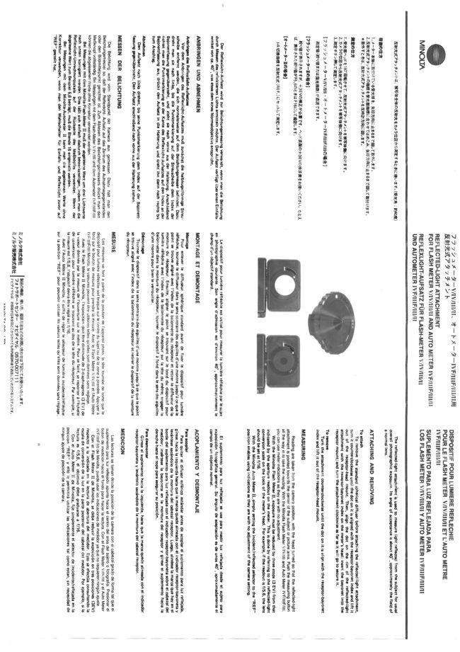
ATTACHING AND REMOVING

To attach

To remove the standard spherical diffuser before attaching the reflected-light attachment,
turn it counterclockwise until the dot on it is aligned with the receptor-bayonet index and lft it
‘out of the receptorhesd mount. Then, align the dot on the rim of the reflected-iight
attachment with the receptor-bayonet index on the meter’s head; insert the bayonet into the
receptor mount; and turn the attachment clockwise as far as it will go to secure it.

To remove
‘Turn the attachment counterclockwise until the dot on it is align with the receptor-bayonet
index and lift it out of the receptorshead mount.

MEASURING

Reading are taken from the camera position, with the head turned so that the reflected-light
attachment is pointed towards the center of the subject or picture area. Push the measuring button
all the way in to take the reading. With the Minolta Flash Meter V/IV/IIl and Auto Meter IVF/IIF/I
you can use meter indications as they are with no adjustment.

With the Minolta Flash Meter II, exposure must be reduced by three stops (3 EV) from that
Indicated by the aperture readout on the meter. This is done by referring to the reflected-ight
‘conversion scale on the back of the meter’s head. For example, if the readout is £/5.6, the lens
should be set at £/16.

With the Minolta Auto Meter II, simply setting the incident reflected selector to the “REF”
Position enables using indications as they are with no adjustment of the camera setting.

El suplemento para luz reflejada se usa para medir luz reflejada desde el sujeto para
‘exposicién forogritica general. Su éngulo de aceptaci6n es de unos 40°, aproximadamente el
‘campo de un objetivo normal.

ACOPLAMIENTO Y DESMONTAJE

Para acopler
Para quitar el difusor esférico estindar antes de acopler el suplemento para luz refiejade,

‘girese hacia la izquierda hasta que la marca quede alineada con el indicador receptor-bayoneta y
levéntese sacindolo de la montura del cabezal r

borde de! suplemento pare luz retlejada con el indi
medidor; insértese Ia bayoneta en la montura del receptor y girese el suplemento hacia la
derecha hasta el tope para asegurer su posicién.

Para desmontar
Girese el suplemento hacia Ia izquierda, hasta que la marca quede alineada con el indicador
raceptor-bayoneta y levintelo sacéndolo de la montura del cabezal receptor.

MEDICION

Las lecturas se toman desde la posicién de la cémara con ei cabezal girado de forma tal que ei
View original page 1
Related documents and language editions
From the M. Butkus Camera Manual Library. Original publisher and archive notices are retained.
Check the model and edition against your equipment.
PDF verified 2026-10-10.