Film cameras
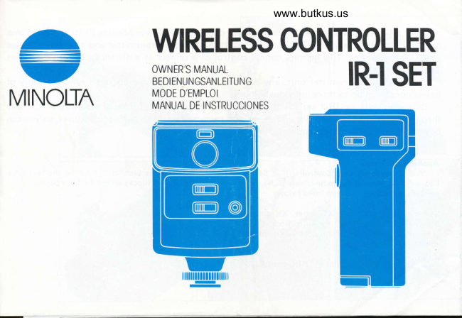
Minolta Wireless Controller IR-1 User manual
User manual for Minolta Wireless Controller IR-1. 20 pages in English. Read the original PDF, download or print a copy without registration.
20 pagesEnglish3.6 MB PDF
Loading your manual…Open PDF directly
Document details
- Brand
- Minolta
- Model / document
- Minolta Wireless Controller IR-1
- Document type
- User manual
- Language
- English
- Pages
- 20
- File size
- 3.6 MB
- Category
- Film cameras
- Document date
- Not specified in catalog
Search available document text
Find a term, then jump to its page in the original PDF. Image-only pages may not be searchable; check the PDF for exact wording and diagrams.
Page 1 · Read text
www.butkus.us
        WRELESS CONTROLLER
                           OWNER'S MANUAL
                            BEDIENUNGSANLEITUNG                                     IR.I SET
MINOLTN          MODEMANUALD'EMPLOIDE INSTRUCCIONES
View original page 1Page 8 · Read text
www.butkus.us

 7 zi'y    l. lR 1 (*ftFIlo6pfia!lLr(HltJH L (Tdu'"
Your lR-1 bracket is contained here. Before
 using the lR-1 set, if necessary, pull it out and
attach  it to the camera.
Hier finden Sie die lR-1-Schiene. Bei Bedarf
ziehen Sie die Schiene heraus und benutzen sie
zur Verbindung des lR-1-Empfdngers mit der
Kamera.
La barrette du systdme de d6clenchement lR-1
est incorpor6e. Avant d'utiliser cet ensemble,
f ixer la d l'appareil si ndc6ssaire.
Su soporte de lR-1 estS contenido aqui. Antes
de usar el lR-1, si es necesario, tirar de 6l y
acoplarlo a la cdmara.
View original page 8
Page 9 · Read text
]F-


                                                                                                                                                                                                                                                                                                                                                                                          r   Your lR-1 set is designed for remote control operation of certain Minolta SLRs and 8mm
cameras. The Receiver senses infrared rays emitted from the Transmitter and transfers a relr
signal to the camera. This permits remote control of a camera at a distance of up to 60 me
 (nearly 200 feet).
   With a single Transmitter unit, any number of cameras can be operated simultaneousll
independently in up to three individual groups.
   Before using your lR-1 set for the first time, please read this manual carefully all the  t
through, while loading batteries and acquainting yourself with its parts and features, so you
begin to realize its broad potential right from the start.

 Applicable Cameras                       NOTE
   Your Minolta Wireless Controller lR-1 Set can         Designations such as "(A-1)" in the text  r,
 be used with Minolta magnetic-release SLRs, Smm     to the lettered blocks on the fold-out pages.
 cameras, and camera systems listed below:
 SLRs: X-700, XD series, XG series, XK ahd XM
 Motor (The Motor Drive 1 or Auto Winder D or G
 is required for automatic film advance except with
 the XK/XM Motors.)
8mm Cameras: XL-401 and 601; XL-Sound 42,64,
 and 84
View original page 9Page 10 · Read text
www.butkus.us
CONTENTS                         NAMES OF PARTS
NAMESOFPARTS                ........1            lR-1 Transmitter
SUMMARY OF OPERATION          .....2         (A-1) Emission head
PREPARATIONS                                      (A-Z) Cfrannel selector
  1. lnstalling batteries                  .....2          (A-31 Transmitting button
  2. Testing batteries                                   (A-4) Batterychamber cover
  3. Receiverconnection              ...,4         (A-51 Power switch
  4. Channel setting                    .......4         (A€) Monitor light
OPERATION
  1. UsewithMotorDrivel            ......5           lR-l Receiver
  2. Usewith Auto Winder Dand G ...  . . . ....5          (B-1) Cord socket
  3. UsewithXKorXMMotor      ........6           lB-21 Channel selector
  4. Usewith XLmoviecameras    .......6           (B-3) Mode-selector/power  switch
OPERATION CHECK                            . ., .. .7         (B-4) Bracket clamp
DIRECT]ONS FOR THE IR.l BRACKET. . . . . .8         {B-5} Attaching bracket (rotates 360')
OPERATING PRECAUTIONS           .. ..9        (86) Operation-indicator light
CAREANDSTORAGE.               ....9          (B-7) Sensor
INTRODUCTION TO THE X-7OO SYSTEM  . . . 1O        (B-81 Battery-check button
SPEC|F|CAT|ONS ...                                   . . .. 11        (B€l Battery-chamber cover
View original page 10Page 11 · Read text
SUMMARY OF OPERATION            PREPARATIONS
(C-11 Load the Transmitter with batteries (see    1. Battery types and loading
      page 2).                                    Transm itter:
                                                          (see     Two-AA size penlight batteries (either sealed(C-2) Load the Receiver with a battery
      page 3).                                      carbon-zinc, al kaline-manganese, or  nickel-
(C-3) Attach the Receiver to the camera and      cadm ium type) supply power for the lR-1
       attach the connecting cord (see page 4).           Transm itter.
(C-4) Set Transmitter and Receiver channels (see    (D-1) Slide the battery chamber cover off in the
      page 4).                                                  direction of the arrow.
(C€l Slide the mode-selector switch to the C or S    lD-21 Load the batteries, making sure their
       position (see page 5).                                     Polarities match the plus and minus indica-
(C6l Check operation of the Transmitter and           tions in the battery chamber.
       Receiver (see page 8).                        (D-31 Slide the battery chamber cover back into
                                                                                  its original position.

                                                        Receiver:
                                            Use one 9v transistor-type battery (Eveready
                                                  216 or equivalent).
                                                 (E-1) Slide the battery chamber cover off in the
                                                                 direction of the arrow.
                                                {G-21 Load the battery, making sure its polarities
                                             match the plus/minus indications in the
                                                               battery chamber.
                                               (E-31 Slide the battery chamber cover back into
                                                                                        its original position.
View original page 11Page 12 · Read text
www.butkus.us
2. Battery check                                     temperature drops. Regardless of which
   Before taking pictures, check for sufficient         battery type is used, remember always to
   battery power.                                             insert fresh batteries and keep a spare set
                                                   with you when using your camera in cold
Tra nsm itter  :                                             weather. (Battery deterioration due to low
(F)  Turn the power switch on and time how          temperatures can be recovered if returned to
      long it takes for the pilot lamp to come on.         normal temperature).
          lf it takes more than 5 seconds, replace the     o Be sure to turn the power switch off when
       batteries with new ones.                      the lR-1 set is not in use. Leaving the
                                                                 receiver on (ie., at the "C" or "S" position)
Receiver:                                                   will exhaust a fresh battery in about 12
(G-11 Slide the mode-selector/power  switch to the          hou rs.
      "C" or "S" position.                       o Mixing battery types, or using an exhausted
(G-2) Press the battery-check button.                      battery with a fresh one could cause battery
   o The operation-lndicator light comes on to          leakage on bursting.
      indicate sufficient battery power. lf the     o lmproper battery loading may not only
     lamp does not light, the battery needs to be          result in operation failure but may also
       replaced.                                      cause battery leakage. Make certain that
   o Battery power level varies with brand, age,          poles are aligned as indicated in the battery
       etc., even though they are the same type.         chamber.
     Even new batteries may slightly deteriorate      o lf either unit of the set is not be used for
      in performance  if used more than a few       more than two weeks,  it is advisable to
     months after production. This may cause         remove the batteries. Leaving the batteries
      the number of operations to differ from the          loaded when not being used for long periods
        specif ications.                        may cause battery leakage and contact
       Batteries by nature tend to lose power as           corrosion.
View original page 12Page 13 · Read text
3. Receiver connection                           (H-51 Direct the Receiver's sensor (generally)
(H-1) Loosen the Receiver's bracket clamp and          towards the Transmitter.
      insert the attaching bracket into  the     o The Receiver rotates 360" (with a detent
      camera's accessory shoe as far as it will go.          every 30o)on the attaching bracket to allow
   o Use the lR-1 Bracket (included with the          a choice of di rections for best reception.
       lR-1 set) when the camera accessory shoe is   4. Channelsetting  (l)
      being used for flash photography or when     The channel selector of the Receiver and
      the Receiver is mounted on an 8mm camera       Transmitter should be set to the same channel
     not equipped with an accessory shoe (see      number for actuation (l-1, l-2).
      page 9).                                  o With two, three, or more Receivers set to
(H-2) To secure the attaching bracket in place,           channels, two or three individual or groups
       rotate the bracket clamp in the direction of          of cameras can be independently controlled
       the arrow until tight.                                with one Transmitter.
(H-3) For applicable magnetic-release SLRs other     o Alternatively, setting Receivers to the same
      than the XM or XK Motor, use the Connect-         channel alloun simultaneous control of any
      ing Cord lR-1(A), included with the set, to        number of cameras with one Transmitter.
     connect the Receiver with the threaded          All Receivers should be aimed towards the
       release socket on the camera body or in its           Transmitter.
       operating button.
(H4l For the XM or XK Motor SLR or the
     XL-401, 601, XL-Sound 42, 64, or 84
     movie cameras, use the Connecting Cord
       lR-l(B), available optionally, to connect the
     Receiver with the accessory-input or
      remote-filming jack or socket on the camera
      body.
View original page 13Page 14 · Read text
www.butkus.us
OPERATION
Continuous or singleframe mode                    2. Turn the frame-speed-selector dial of Motor
   The Receiver's mode-selector switch is used to           Drive 1 to the "S" position.
set the unit for single-frame or continuous ex-      o Each transmission releases the shutter and
posures. Set the switch to the "S" position for          advances film-
single-frame mode or the "C" position for continu-     (2) Continuous operation
ous mode.                                         1. Set the Receiver's mode-selector to the "C"
  To prevent accidental waste of film, make sure           position.
                                                                                                                                                                                              1you set the desired mode before pressing the      2. Turn the selector dial on the Motor Drive
transmitting buttion.                                         to the "Hi" or "Lo" position.
                                          o Pressing the transmitting button begi ns con-
Single-f rame exposures                                      tinuous operation. The camera will continue
   Each press of the transmitting button releases         to make exposures until the button  is
the shutter (and advances film by one frame with      .     pressed a second time (or film is exhausted).movie cameras or a still camera with a motor/    (3) Bulb exposures
winder).                                           1. Set camera shutter speed to the "8" (bulb)
Continuous operation                                            position.
  One press of the transmitting button starts      2. Slide the Receiver's mode selector to the
operation, and the film advances at the continuous         "C" position.
frame rate set on the set on the motor/winder.      3. Set the frame-speed-selector  dial on the
Pressing the button a second time stops operation.         Motor Drive 1 to the "Hi", "Lo", or "S"
                                                                  position.
1. Use with Motor Drive 1                       o Pressing the transmitting button opens the
(1 ) Single-frame exposures                                 camera shutter.
     1 . Set the Receiver's mode selector switch to          Pressing it a second time closes the shutter
      the "S" position.                                and advances  f ilm.
View original page 14Page 15 · Read text
2. Use with Auto Winders D and G                     camera is set to the "8" position and the
 ( 1 ) Single-frame exposures                                lR-l set to the "C" mode, Pressing the
   1. Set the Receiver's mode-selector switch to         transmitting button begins continuous
       the S position.                                      operation at a shutter speed of 11100 sec.).
   2. Turn on the Auto Winder main switch,        3. Use with XM or MK Motor
   o Pressi ng the transmitting button releases the     (1 ) Single-frame exposures
       shutter and advances film.                      1. Set the Receiver's mode selector switch to
(2 ) Continuous shooting                                    the "S" position.
   1. Set the Receiver's mode-selector switch to      2. Turn the camera's frame-speed dial to the S
       the C position.                                           position.
   2. Turn on the Auto Winder main switch.          o Pressing the transmitting button once
   o Pressing the transmitti ng button starts           releases the shutter and advances the film.
      continuous exposures. The camera will     (2) Continuous operation
      continue to ma ke exposures until the      1. Set the Receiver's mode-selector switch to
      button is pressed a second time.                      the "C" position.
 (3) Bulb exposures (XD-series cameras excluded)        2. Turn the camera's frame-speed  dial to the 1,
                                                                                      as desired.     1 . Set the camera shutter-speed dial to the         2,3 or "H" position,
                                                                                                       begins     "B" (bulb) Position'                      o Pressing the transmitting button
   2. Turn the Receiver's mode-selector switch to           conti nuous operation. The camera will con-
       the "C" position.                                  tinue to make exposures at two set rate
   3. Turn on the Auto Winder main switch.                 until the button is pressed a second time or
    o Pressing the transmitting button opens the          film is exhausted.
      camera shutter.                         o Bulb exposures are impossible with the lR-1
       Pressing it a second time closes the shutter            set and the XM or XK motor.
      and advances  f ilm.
    o Bulb exposures are not possible with the
       lR-1 and the XD series cameras. (lf an XD
View original page 15Page 16 · Read text
www.butkus.us
4. Use with XL or XL-Sound movie cameras
(1 ) Continuous Operation
   1. Set the Receiver's mode-selector switch to
      the "C" position.
   2. Turn the function selector on XL cameras
     or the run/lock switch on XL-Sound
      cameras to "RUN".
   o Pressing the transmitting button begins
       operation. The camera will continue operat-
       ing untilthe button is pressed a second time.
(2) Single-f rame operation
   1. For the XL401 or 601, set the Receiver's
    mode selector to the "S" position; with the
     XL-Sound 42, 64, or 84, to the "C"
       position.
  2. Turn the function selector of XL models or
     'the frame-speed selector of  XL-Sound
      models to "1".
   o With XL models, each press of the trans-
      mitting button expose a single frame and
      advances film.
   o With XL-Sound models, pressing the
      transmitting button will expose a frame
      after a delay of one second, then advance
     the film. (tf the receiver's mode selector is
     set to "S", the camera will not function
       properly.   )
View original page 16Page 17 · Read text
OPERATION CHECK
  Maximum remote-control range of your lR-l   o After operation check, reattach the connecting
set is 60 meters (about 2OO feet) when the     cord to the camera's remote-release terminal
Transmitter's flash head and Receiver's sensor are      and the Receiver's cord socket.
facing each other unobstructed. Maximum range   o When the Transmitter and Receiver are not
decreases  if there is an obstacle between the      facing each other, you may utilize reflecting
Transmitter and Receiver, direct sunlight on the      surfaces, such as a wall or the ground, to
sensor, misty air, or other adverse weather condi-      operate the lR-l . Be sure to carry out an
tions. Before taking pictures, be sure to make an      operation check in this situation.
operation check under actual conditions.          o lf the operation-indicator  is not visible due to
1. Turn on the Receiver's mode-selector switch     camera position, it  is possible to make an
   and set it to the "C" or "S" position (C-5).           operation check by connecting the lR-1 to the
 o lf the camera is loaded with film, remove the     camera and confi rming proper operation by the
   cord that connects the camera's remote-release      camera's  f rame counter. In this case, the
    terminal and the Receiver's cord socket.              operation check should be done before loading
2. With the Transmitter and Receiver set to the      the camera with film.
   same channel, press the transmitting button to
    simulate operation (C-4).
3. The operation-display lamp confirms receiver
   ope ration.
 o The lamp lights only once for single-frame
   shooting, and flashes about twice per second
   du  ri ng conti nuous shoot ing.
View original page 17Page 18 · Read text
www.butkus.us

                                                                                                                                                                                                                                                               IDIRECTIONS FOR THE IR.l BRACKET  CARE AND STORAGE
  The lR-l Bracket is useful for attaching the   1. Clean the Transmitter and Receiver using a dry
Receiver when no accessory shoe is available (as      or silicone-impregnated cloth. Never use sol-
with the XM or XK Motors or XL or XL-Sound       vents such as paint thinner or benzine.
movie cameras), when an Electrof lash is being   2. The lR-1 Transmitter has a  high-voltage
used, or for better reception from various angles.        electrical circuit. Therefore, do not attempt to
                                                      disassemble the Transmitter.  lf any problem
(J-1) No accessory shoe available                       occurs with the Transmitter or Receiver, please
                                                                                                        theU-2l. With a strobe unit                             consult your nearest Minolta dealer or
(J-31 With Transmitter directed upward toward       camera shop where your set was purchased.                                            3.  lf the set is not to be used for more than two       Receiver or from bottom
                                                                                             and(J4) Camera positioned vertically                     weeks, remove the batteries from the units                                                   store them in a cool dry place. Leaving the
                                                             units loaded with batteries for long periods may
                                                       cause battery leakage and contact corrosion.OPERATING PRECAUTIONS                                            4. Exposing the qnits to high temperatures  (parti-
                                                          cularly inside a car in summer) or high humidi-1. When two or three Receivers are used in the                                                  ty during storage will cause damage to the   same area, be sure to set them to different         u nits.    unless simultaneous atuation  is desired.
2. For automatic-exposure shooting, use an eye-
   piece cap to prevent light coming from the
   winder eyepiece.
View original page 18Page 20 · Read text
www.butkus.usTECHNICAL DETAILS
                  Type:  Compact ransmitter-receiver set for remote camera control by near-
                             infrared radiation
           Max. range:  Approx.60m (200 ft.)
      Operating channels:  Three
       Actuation modes:  Continuous (C) and single-frame  (S)
        Transmitter unit:  Transmissionangle: 50"vertically
                                            70" horizontally
                      Number of bursts*:  Approx. 2,000 with sealed carbon-zinc  cells
                                              Approx. 4,000 with  al kaline-manganese  cells
                             Triggering interval*:  0.5 sec.
                                                        (* under Minolta standard testing conditions)
           Receiver unit:  Reception angle:          80" vertically and horizontallY
                        Continuous stand-by time: 12 hrs. with fresh battery specified
         Power sources:  Transmitter: Two AA+ize 1.5v sealed carbon-zinc, alkaline-manganese,
                                     or 1.2v nickelcadmium  cells
                             Receiver: One 9v battery, Everady 216 or equivalent
                 Weights:  Transmitter:  1 109 B-718 oz.) without power cells
                             Receiver: 1009 (3-1 12 oz.l without battery
     Sizes(WxHxDl:  Transmitter: 34 x 116 x 70mm n-il16 x4-9116 x2-3l4in.l
                                fleceiver: 6O x 94 x 43mm 12-5116 x 3-1 1 116 x 1-1 1/16 in.)
              Accessories:   Included with unit: Bracket lR-1 (for attaching Receiver at camera
                            position when accessory shoe cannot be used, etc.) and Connecting Cord
                             lR-l (A) (for connecting Receiver with camera shutter-release socket)
                           Avaiiable optionally  : Connecting Cord   I R-l (B) (for connecting Receiver
                          with XM (or XKor X-1) Motor or suitably equipped Super-8 movie
                        cameras (X L-401 , 601 ; X L-Sound 42,64,84l.
                                                        Specif ications subject to change without notice
View original page 20Related documents and language editions
From the M. Butkus archive. Original publisher and archive notices are retained.
Check the model and edition against your equipment.
PDF verified 2026-10-10.