Flashes & lighting
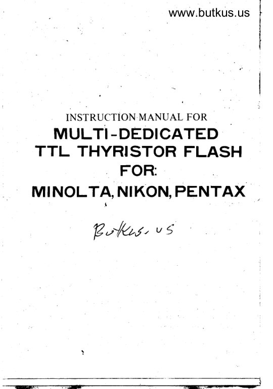
Mulit-dedicated TTL Thyristor Flash Minolta, Nikon, Pentax User manual
User manual for Mulit-dedicated TTL Thyristor Flash Minolta, Nikon, Pentax. 17 pages in English. Read the original PDF, download or print a copy without registration.
17 pagesEnglish1.2 MB PDF
Loading your manual…Open PDF directly
Document details
- Brand
- Nikon
- Model / document
- Mulit-dedicated TTL Thyristor Flash Minolta, Nikon, Pentax
- Document type
- User manual
- Language
- English
- Pages
- 17
- File size
- 1.2 MB
- Category
- Flashes & lighting
- Document date
- Not specified in catalog
Search available document text
Find a term, then jump to its page in the original PDF. Image-only pages may not be searchable; check the PDF for exact wording and diagrams.
Page 1 · Read text
www.butkus.us


     INSTRUCTION MANUAL FOR
  MULT| -oEorcATED
TTL THYRISTOR FLASH
          FOR:
MINOLTA, NIKON, PENTAX
                                           I
          B,-'//at' v 5
View original page 1Page 3 · Read text
5. INSTALL THE FLASH ON THE CAMERA
      To prevent possible camera damage - the on/off switch should     be at"off"  (red area not showing) bef ore installing or removing the
      flash from the camera. Also the knurled locking ring should be all
      the way up. Hold th.e flash unit close to its foot, and slide the flash
      foot into the camera shoe until  it stops. lf the contact pins "catch"
     on the edge of the shoe, you may use the tip of a pencil to push the
      pins up. Or you may wiggle the flash gently until the foot slides in
       all the way. lf flash is not pushed completely all the way into the
     camera shoe, the flash may fail to operate correctly. Tighten the
      knurled locking ring until it locks the flash securely into the hot-
       sh oe.
         lmoortant: re-check to be sure that the Camera Selector Switch
     on the  f lash is set to match your camera.
     6. TURN THE FLASH TO "ON"
       Move the on-off switch to the on position (red area showing).
      After turning the switch to "on", you will hear a faint humming
     sound -  the flash capacitor is being charged. After 8-10 seconds
      {with fresh batteries). the Readv-Lite on the rear of the flash should
     go on. Also, a "Flash-Ready" signal will go on in the camera's view-
__   finder this is usually a smal I red light (LED) next to"1160" second.*\         Note: on certain camera models all the LED's GO OUTwhen tfre          I
       flash is ready.
     7. SETTING THE FLASH FOR THE AUTOMATIC APERTURE.
       PRIORITY MODE (NON-TTL AUTO MODE):
        Re-check the ASA switch on both flash and camera. For auto-
     matic (Non-TTL) aperture-priority operation, set the "STD-TTL"
     switch on your flash'(not on all models) to "STD" (standard).
     For operation in the "TTL" mode (optional feattr re), please see
     your camera instruction booklet (not all cameras operate in the TTL
     mode), Also, see the enclosed special instructions.
         Set the computer switch to one of the two automatic/computer
     settings:eitherredorgreen/b|ue.operationintheManual/White
    mode ("M") is described in Section (12).
        Use the Automatic Red setting to obtain maximum flash range,
     and fastest recvcling.
        Use the Automatic Blue/Green setting to obtain maximum depth
      o{ field.
        Use the Manual White setting for distances beyond the maximum
     auto flash range and/or for films outside the ASA range' On some
 .    models: this is also the "TTL" position,
View original page 3Page 4 · Read text
www.butkus.us


             EXPRESS INSTRUCTIONS

       1. Load batteries and set Selector Switch to matcn your camera.
     2.Set the ASA film speed on the flash unit and on the camera.
       3. Install the flash on the camera. Be sure that all switches are at
     "OFF", before installing or removing flash from camera.
    4.Turn the camera switch to ,.Auto,,
     5.Turn the flash on-off switch to',On.,,
    6.Turn the optional "TTL-STD', switch to ,,STD,, (no switch on
      some models).
    7.Turn the flash "Computer" switch to ,,Red.,,
    8. Set camera lens to the F/Stop shown in the flash,,F/Stop
       Window."
t.     9. Make sure that the flash ready lamp is on.
    10' Look in the viewfinder and compose the picture and focus the
                            I ens.
      I l. Press the shutter button half-way to turn on the viewfinder
        indicators. Make sure that the flash-ready indicator is on.
     1 2. Press the shutter button all the way to take the picture.
   13.Turn the flash and the camera to "oFF" when you finish takinq $
        p   i ctu res.
View original page 4Page 5 · Read text
8. SET THE CAMERA
      A) Shutter:
        Turn the camera on-off switch to "on,,. Set the shutter dial
          to "Auto" ("A") or to any setting Except "B".
       On cameras equipped with both "A" ancJ ,,p,, settings, use
          the "A" setting. See the separate instruction sheet for infor-
        mation regarding PROGRAM/TTL Operation (optional)
            featu  r e)
     B) Lens Apenure (F/Stop):
         Set tire iens aperture (F/Stop). Find the correct F/Stop   f rum
          the exposure calculator on the back of the .lash. Read it inside
        the F/Stop window, or inside the colored area (red or bluei
         green) on the auto exposure table. Example: Film: 100 ASA.
        Computer: Red Dot. Lens F/Stop: Fl2. Exampte: Film: 400
       ASA. Computer: Green/Blue Dot. Lens F/Stop: F/g.
     C) Lens Focus & Flash Range:
       You must, of course, adjust the lens to the correct distance
           setting. The "Maximum Flash Range" of the flash unit on
         automatic-aperture  priority operation can be determined
                     f rom the calculator.
                               lr"J Setti.:g 40;u;.
                    Greeni Blue Setting: 20 feeti-i".     rl     Pictures taken at distances greater than the maximum Flash
         Range will be underexposed (too dark).
       The minimum distance for Automatic (Computer) operation
              is 3 feet. Pictures taken at closer distances will be over-exposed
         (too iight). Switch over to "manual " control (the ,,white,.
          setting on the computer selector switch) for such situations.
      Some models have flash ranges up to 50 feet. Also. the
         optional zoom lens on some models will extend the flash
           range.
       NOTE: The maximum and minimum operating ranges stay
       unchanged for all film speeds (ASA) in Aperture-prioritV
         Mode.
     D) On TTL/PROGRAM setting the maximum flash range varies
        according to the FiStop selected by the flash/camera/user.
               lf you knowthe F/Stop set on the lens then you can estimate
         the maximum range  f rom the calculator  scare.
        Example: lf the film is 100 ASA and the f/stop is f/2.g    set                                                                       -        the calculator dial to 100 ASA. Then the maximum auto
          flash range is 30FEET.
View original page 5Page 6 · Read text
www.butkus.us


           DETAILED INSTRUCTIONS
1. OPERATING CONTROLS
    Familiarize yourself with the operating controls of the flash unit:
        1 - Batterv Door
       2 - TTL-Standard Switch (on some models only)
       3 - Ready Lightand Test Button (location may vary)
     4 -  "Auto OK" Flash Verification Light. (location may
             vary  )
       5 - ON-OFF Switch
       6 -  Flash Range lndicator
                                     models)       7 - ASA Switch (not on all
       8 -  F/Stop window
      9 - Computer switch (location may vary)
      10 -  Flash Window
      11 - Mounting Foot and Locking Ring
      12 - Auto Exposure Table
      13 - Carnera Selector Switch {location may vary)Note: On some flashes there is no TTL-Standard switch.
     The 3-position computer switch includes the "TTL" Setting,
      which is the same as the White/Manual ("M") setting.
Location of controls may vary on different models.
View original page 6Page 7 · Read text
Or: you can use the manual exposure table to estimate the
    maximum flash range.
    Example: lf the film is 100 ASA                                            -  look down the,,1OO,,    column until you find your f/stop (2.8), look across horizon_
     tally and you will  f ind the range ,,30 Feet",
    Note: Some combi nations of pentax cameras and certain
      flash models will not change the shutter speed automatically,
      Please set the shutter dial to "X" synch (1 ll2S second).
  bl covrposE AND Focus
    Hord the camera up to your eye and compose the picture, and
 fcuus; the lens.
 10) A FINAL CHECK
     Look into the viewfinder  ar,d press the shutter button halfway,
 to turn on the viewf inder indicators.
    When the flash is fully charged (ready light is on), you..r,ill see
a "Flash Ready" indicator in the viewfinder. In addition to, or
 instead of the flash indicator, depending on the camera model
other indicators will go on. see your camera instruction manual
 for detai    I s.
        lf you do not see a "Flash Indlcator,, in the vielrvf inder _
please recheck the flash batteries, the on-off switches (on the flash
and on the camera), the Ready-Lite, and the mounting of the flash
                                                                                                             signed                                                                                                        by mike butkuson the camera.                                                                                        DigitallyDN: cn=mike                                                                                                                         butkus,
                                                                                                 o=orphancameras, ou=29,                      mike butkus  email=mike@butkus.org, c=US11) TAKE THE PICTURE                                                 Date: 2018.12.10 14:45:17 -05'00'
      Press the shutter button all the way to take the picture. lf you
are not taking any additional  pictures, be sure to turn the flash and
camera switches to "OFF".
121 HOW TO USE MANUAL OPERATION
    The white-dot manual setting (M) is used when the subject  is
beyond the automatic flash range, or for films outside the ASA
range, or for special applications. To find the correct f/stop please
use the manual calculator dial on the back of the flash unit.
    Some flash models do not have a manual calculator  dial.
     Please refer to the table below:
View original page 7Page 8 · Read text
www.butkus.us
2. WHAT WILL THE FLASH DO?
   When the flash becomes fully charged (ready light is "ON"), the
flash will automatically adjust the shutter speed to "X-synch," and
then give you an indication in the camera viewfinder that it is fully
charged. This is usually a small Red Light (LED) next to ''1160".
See your camera instruction manual for fulldetails.
   The flash photocell sensor will automatically measure the light
reflected back from the subject, and then it will cut off the light
output of the flash when the subject'has received the correct amount
of light. Certain flash models will even measure the light Through
The camera Lens (TTL).
   The flash "AUTO OK" light will tell you if the subject is within
the correct operating range of the flash.
  When the flash is turned off (or if the ready light is off), the
 f lash will shift the camera automatically back into the auto exposure
(AE) mode. You may, therefore, leave the  f lash attached to the
camera even during outdoor non-flash photography.
  On certain camera models, the flash willautomatically select the
correct lens aperture (F/Stop) according to your film ASA speed,
and the computer setting you have selected (red, green/ blue, or
TTL).
   This flash will operate in a dedicated mode with most camera
models made by: Minolta, Nikon. Pentax.
   The flash can also be used in a non-dedicated mode with many
other cameras.
   IMPORTANT: Before you proceed any further, please set the
Selector Switch on the flash to match your camera.
Also - please read your camera's instruction manual carefully,
3. LOAD THE BATTERIES
   Open the battery door by sliding it down. Insert "AA" alkaline
batteries according to the plus and minus. symbols inside the battery
compartment Slide the door back on while pressing the batteries
down. The flash will not operate  if the batteries have been inserted
 i ncorrectl y.
  We do not recommend Ni-Cad Rechargeable batteries or Low-
cost carbon batteries (so-called "Heavy Duty" Batteries).
4. SET THE ASA FILM SPEED
   Set the ASA switch on the camera and on the flash to match
your film as closely as possible. Some models do not have an ASA
switch. lf your film ASA is outside the range of the settingson the
flash, (or the lens/camera combination ), then please switch to
manual operation (see below).
View original page 8
Page 9 · Read text
MANUAL EXPOSURE TABLE

                            100                                                         1 000
FEET
  3     11    16     22    32     45       64
  5     8      11     16    22     32       45
  7      5.6     8     11    16     22       32
 10     4      5.6      8    11     16       22
 13      2.8     4      5.6        I      11        16
 20      2     2.8     4     5.6     8         11
 30      1.4     2      2.8    4      5.6       8
 40                   1.4      2    2.8     4         5.6
 60                   1.4    2     2.8        4
 80                          1.4     2        2.8
The above table can also be used to estimate the maximum flash
range for different apertures in the TTL/PROGRAM mode.
Examole: lOOO ASA at F14. The maximum flash range is: 60 Feet'
Or-you can use the GuicJe-Number system:
USING GUIDE NUMBERS TO CALCULATE EXPOSURE
lf your film speed or your camera-to-subject distance is not on the
Exposure table, please proceed as follows:
Divide the "Flash Guide Number" (you will find it in the table
below) by the "camera-to-sr,b.iect distance." The result is your
F/Stop.
FLASH GUIDE NUMBER         = LENS F/Stoo
Camera-to-Su b ject Distance
Example: Distance: 10 feet   Film: 160 ASA
       GN Table Shows: 100
        To find F/Stop: Divide 100 bY 10 F/10
Example: Distance: 50 feet   Film: 400 ASA
       GN Table Shows: 160
         F/stop =         FB.2          S
Guide Numbers in Feet fASA-FEET):
ASA Film Speed 25 50 64 80 100 125 160 200 400 1000
GN (feet)    40 56 62 68 80 90 100 110 160 24O
View original page 9Page 10 · Read text
www.butkus.us

 SETTTNG THF_lLagX  lllD  THE CAMERA FOR MANUAL
 OPERATION
 - Set the computer switch to theWhite Dot (manual).
 -   lf your flash                 has a "TTL-standard"  srnuitch - then set it to "stan-   dard".
 -  Set the camera lens to the desired f/stop (see instructions above).
 -  Set the camera shutter to X-Synch (1/60 or 1l9O - or 11125 -   see your camera's manual).
  DO NOT set the shutter to Auto (A) or Program (P).
 On some cameras the TTL-mode will continue to function even when
 the shutter dial is set to X-synch. In these cases, set the flash com-
 puter switch to "Red," and cover up the flash computer photocell
 sensor (small opening on front of flash unit) with a piece of black
 tape or black paper. This will disable the auto-computer and let the
 flash fire at its full-power.

                                                                            :r€''13.HOW TO USE THE OPTIONAL "Auto OK" Light:
   On some flash models, there is an "Auto OK" light located near
 the ON-OFF switch. This is also known as "Confidence Light" or
 "Flash Verif ication Light."
   The light can be used to test your computer setting and to be
 sure that you are within the shooting range of the flash unit.The
_sensitivity of the flash reaches up to 40 feet. However, the effective
 auto shooting range may be reduced by many factors: dark subject
 -  lack of good reflecting surfaces -  very high ceilings - outdoor
shot at night -  using bounce flash at excessive distances -  etc.   To verify that you are within the effective shooting range, pro-
ceed as follows:
   A) Turn flash switch to "ON"
   B) Wait for ready light to go on.
   C) Adjust the bounce ref lector to the desired position.
   D) Adjust the computer switch to Red or Green (the "Auto OK"'
         lite has no meaning on the "M" setting). The Red setting  is
      recommended for bounce.
   E) Aim the camera with the flash at your subject.
   F) Keep looking at the "Auto OK" window - while pressing the        test button. The  f lash will  f ire.
View original page 10Page 11 · Read text
-  Try a different brand of batteries. There are differences
        between batteries.
        Don't use rechargeable  (Ni-Clad) batteries. They could
       damage the  f lash unit.
 2 eacxcnoUNDS:
       Keep your subject close to the background. Try to use a
          bright colorful background.
        Avoid dark walls or large halls.
         Flash pictures taken at night outdoors will be dark'. Open
         the lens aperture setting one or two extra F/Stops.
 3. DISTANCE
      When shooting at distances greatel than 15-20 feet. wait
    an extra 10-15 seconds after the Ready Lite goes on. This
     allows the unit to become fully charged.
 4. lF YOUR FLASH UNIT DOES NOT FLASH                       :. ..
      .   First   Remove the  f lash unit  f rom the camera.               -   a  Check proper placement of batteries.
   o  Check ON/OFF Switch (red area visible means "ON").
   o   lf Vou can hear a humming noise, wait a while longer.
   o   lf Ready Lite finally comes on (after 30 seconds or more) a,l
         - you need fresh batteries'
   o   lf in Doubt about your batteries, ask your Photo Dcaler
  .      to test them for You.    Remember: The Flash will not fire if the flash onlolf switch
       is at "off ."
 5. BEFORE YOU GO ON A TRIP OR BEFQRE YOU TAKE
   ANY ESPECIALLY IMPORTANT PICTURES:
     Please shoot one roll and check the results.
 6. Sometimes people's eyes appear red in flash pictures. This is
    most common when your subject has blue eyes. You can
     minimize the red reflections by turning on all the lights  irr the
    room. Then ask your subject to look directly at one of the
    room lights (this will cause the eye pupil to close slightly,
     thus reducing the amount of reflection).
  7. You can keep your flash capacitor operating at peak efficiency
    by letting the flash unit charge up about once a month and
      firing  it several times.
8. Certain flash rnodels have a setting for MACRO (CLOSE UPI
   photography. When takirrg macro photograph closer than 24
View original page 11Page 12 · Read text
www.butkus.us

   G) lf you see a Green lite go on briefly behind the "Auto OK"
      window, you will get a good picture.
   H) lf you don't seea Green lite,you have to increasethe amount
      of light reaching your subject by doing one or all of the
                   f ol lowi ng:
      a) move closer to the subject
      b) re-adjust the bounce angle
      c) use head-on flash (no bounce)
      d) go from the "Green" range to the "Red" range,
     l)  Keep testing until the Green lite goes on (brief ly).
NOTE: The "Auto OK" light will notgive a reliable indication with
the above test procedure when the flash is used in the TTL Mode,
or the Program Mode.
    ln the Program/TTL mode the camera will select a large aper-
ture if the subject brightness is low. and a small aperture if the
subject brightness is high.
   The flash range and the depth-of-field depends on the aperture
selected.
   Therefore, when you are uncertain about the flash range, or
if you want to control thr: deptl-;,lf-fieid,  it is i"commended to use
the flash in the automatic (NON-TTL) mode.
   However,  if your camera  is not loaded with film. you can use the
"Auto OK" light for testing difficult combinations of F/Stops ancl
subject distances in the TTL or Program mode. Be sure to set the
correct ASA speed on the camera and the flash.
   Repeat all the steps listed above except:
   Step (D): Adjust the computer switch to "TTL" (not Red or
              Blue/Green  ).
   Step (F): Press the Shutter button (not the Ready/Test Button.)
                                                                            lens   Step (H): lf you Oon t see a green lite - then open up the             aperture (example: move from FlSto Fl4.l
l4.OPTIONAL FEATURES
  Some  f lash models are equipped with additional features:
   A) Bounce
         Grasp the flash head and tilt  it upwards to the  desi red
      angle (450, 600, 760 or 90o.)
        Bounce flash avoids the harsh lighting of normal flash, it
View original page 12Page 13 · Read text
inches, remove the 5 degree rubber stop which is located under
   the bounce head.
9. New camera models are being introduced constantly.
   This part is intended to provide you with the latest available
    il,formation.
    Generally - there are 4 possible   f lash operating modes:
   A) Automatic Apertu re-Priority
   B) Manual
   C) TTL Aperture Priority
   D) TTL Program
   The first 2 mocies are covered in the main Instruction Booklet.
   The other 2 modes are covered here.
TTL APERTURE PRIORITY MODh
Only caineras having a TTL (Through-the-lens)  capabilitt'will
 operate in this mode. A partial lisi ot cameras follows:
    Minolta: X-700, X-570, 7000 (Maxxum),  etc.
   Nikon: FG. etc.
    Pentax: Super A Program, LX, etc..                                         "i*l
   Follow these 5 simple steps:
1. Set ASA dials on camera and  f lash.                                         {r*2. Set flash switch to "TTL."
3. Set the desired FlStop on the camera lens. Use big lens openings
    (F12, F12.8, etc.) for distant subjects and for fast flash recycling.
   Use smaller lens openings F/11 , F116l for increased depth of
        f ield.
4. Set the camera shutter dial to "A" (Auto).
5. Do not exceed the TTL/Auto Flash range for your F/Stop and
      f ilm combination. The maximum ranges are:


To estimate the maximum flash range, you can also use the Calcula-
 tor Dial on the back of the flash,and/or the manual Exposure Table.
 See the main instruction manual  f or details.
TTL-PROGRAM MODE
The Minota X-700 and /000 (Marxum) cameras have a "P"
 (Program) Mode that operates with flash
View original page 13Page 14 · Read text
www.butkus.us

     is besr suited for portraits of people'Try your first shots with
   your subject 6-10 feet and the reflector bounced at the 45o
    position.
     The maximum auto flash range is reduced from 40 feet
    to about 20 feet in the bounce-mode.
    Do Not use bounce flash with colored ceilings or very
   high ceilings.
  NOTE: When you are using the bounce feature    please                                                             -    select the red computer setting Reason: to cornpensate for
   the light lost by reflection from the ceiling. Also   you                                                               -   should make sure that you are within the auto flash range by
    using the "Auto OK" light (see instructions below).
B) ZOOM LENS:
     For most shots you may leave the Zoom Lens in the
  'NORMAL' or 'WIDE' position. However if you are using a
                                                              can   telephoto lens or a Zoom lens on your camera - you    increase the range of the flash unit by moving the flash Zoom
   Lens to'TELE'.The  flash range is shown on the label next to
   the Zoom Lens.
C) SWIVEL:
      This feature is useful when you want tb use bounce flash
   with the camera in a Vertical position.
D) Dual Fla_sh Heads:
  PHOTOGRAPHIC EFFECTS BY DIRECT AND INDIRECT
  FLASH LIGHTS
  The Dual Flash Head are controlled by a
   Two-position Switch located on the Front
   of the  f lash unit.
  The Switch is labelled:  1 -2    ln position 1 : The Main flash Only will Fire.
   In position 2 : Both Flashes will Fire.
     By normal direct flash. you may produce pictures with
   excessive shadows behind the subjects or over bright sub.iects
  even when output light is controlled by AUTOMATIC
   ope rati on   .
       In order to overcome this problem the BOUNCE FLASH
  was introduced to assist photographers in taking less harsh
     lit pictures without shadows. For taking even better pictures,
   this unit provides DUAL FLASH to give the advantage of
   both direct and indirect lighting.
View original page 14Page 15 · Read text
In this mode the camera selects an F/Stop based on the film speeo
    and the existing light conditions. The Program is biased toward
     small F/Stops in order to provide a large depth of field.
    1. Set ASA dials on camera &  f lash.
    2. Set flash Sawitch to "TTL"
    3. Set the lens to:mallest F/Stop (F/16 or Fl22l                                                                -   it is usually       marked in Green.
    4. Set the camera shutter diai to "P" (Program). (Easy reminder:
        Set camera controls to "GREEN".)
    5. The flash range will depend on your film speed and on the
      amount of ambient light. We reconrmend that you stay within
  .     the range of 5-25 feet. For smaller or larger distances, please
      use the Aperture Priority Flash Mode (TTL or Automatic).
       Generally -  your results will be more predictable in the two        Aperture-Prioriry Modes.
    SPECIAL NOTES
    1. Be sure to read yot'r Cameras Manual Carefully.
    2. On certain Pentax Program cameras the fLash wrll not change
frlr;    the shutter speed automatically.  lf y<,u own one of th;G mo?'e-i;
         - please set the shutter to X-synch l1 1125 second).    3. With certain combinatrons of flashes and cameras c,rch as the
       Minolta XD-11, X-570 or X-370: the viewfinder indicators will
       ryut  when the flash is readY.
   lO.NOTE FOR OWNEFS OF PENTAX CAMERAS
       a. Several Pentax cameras have an Automatic Flash Program
            built into the camera memory- sVstem. The camera will Auto-
           matically select the correct F/Stop based on ASA setting
          of the camera (Be sure to set it to match your film), and
          the setting of Flash computer switch: RED - BLUE - TTL.       b. Please note that there are variations between  f lashes and
         cameras. Therefore, we recommend that you take test
           pictures at both the Red and the Blue settings. Compare
         your results, and then keep using the one setting that gives
         you the most pleasing pictures.
       c. The TTL setting can be used only on cameras that have
       a TTL Capability (For example: PENTAX SUPER PRO
        GRAM). Please read your camera instrustion  nranual.
View original page 15Page 16 · Read text
www.butkus.us


          (a) Direct Flash       (b) lndirect Flash (c) Dual Flashes by
                                                         Direct and
                                                         Indirect Lights
      1 5.OPERATION WITH NON-DEDICATED CAMERAS
       This flash can be used on most non-dedicated cameras if they are
   equipped with a standard Hot-Shoe Flash attachment. A PC Synch-
   cord is not available for this flash.
     1 6. DEDICATED OFF.CAMERA FLASH
      Off-Camera Extension Cords (brand name: "Duo-Synch" and
    others) are available at your photo dealer.
1S Tz.HELPFUL HrNTs
      1. BATTERIES
             .  Check batteries for freshness when you purchase them
             (Most stores have a battery tester).
             .  Turn switch to "OFF" between pictures.
             Replace batteries when recycling time exceeds 30 seconds..
       o  Remove the batteries if not using flash for a long time.
       o  Loading The Batteries: Please be careful when inserting
             the batteries. Pushing them in too forcefully will bend the
               flash contacts downwards and prevent them  f rom making
             contact with the batteries. lf this happens. simply lift the
               tips of the flash contacts gently with your finger or with a
              penci L
       o   lf your Flash Unit ls Not Charging Properly:
               Be sure yourbatteriesare fresh Al kaline type batteries.
            Be sure the batteries are properly inserted, and the
                switch is "ON" (red area must be showing).
              Check to see if the battery contacts are "collapsed"
                {bent downwards too much}. Lift them if necessary.
View original page 16Page 17 · Read text
'  LIMITED WARRANTY
Your Product has been built and inspected with great care. lt  is
warranted for a period of ten years from Date of Purchase.
1. What is covered by the Warranty
   Any part which because of manufacturing defects or poor work-
manship fails to functions properly under normal use will be fixed
at no charge for parts and labor. lf we are unable to fix your unit it
will be replaced at our option,
2. What is not covered by the Warranty
   Consequential or incidental damages: damages from delay or
loss of use of equipment or damaged film (some states do not allow
the exclusion or limitation of incidental or consequential damages.
so the above limitation or exclusion may not apply to you).
   Malfunctions resulting from misuse, tampering, unauthorized
repairs, modification, or accidents, batteries and/or damage caused
by an',' defe.  rr ttie unit.
3. What to do when you need Service
   Package the unit carefully in a carton which allows at least 3
inches of packing material on all sides.
   Ship it Prepaid and insured by Parcel Post or by U.P.S. to:
     FLASH SERVICE. CENTER
     85 5th Avenue; bldg. 16 Floor12
       Paterson, t\J 07524
Include the following in your package
     1 . Proof-of-Purchase showing date and place of purchase.
   2. A description of the problem,
   3. Sample pictures  if available.
   4. A check or money order for $4.95 for handling and return
shipping costs.
   5. Please tell us the make and model number of your camera.
     When Service is completed, we will return your unit to you
  :   Prepaid.}J}.W FLASI{ SERVICE EENTER
   oNE IIOLLYWOOD AVE.' BLDG [e,
   HO-HO-KUS, NJ 07423, USA
View original page 17Related documents and language editions
From the M. Butkus archive. Original publisher and archive notices are retained.
Check the model and edition against your equipment.
PDF verified 2026-10-10.