Film cameras
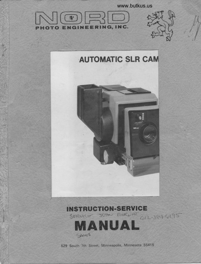
NORD Auto SLR User manual
User manual for NORD Auto SLR. 32 pages in English. Read the original PDF, download or print a copy without registration.
32 pagesEnglish2.2 MB PDF
Loading your manual…Open PDF directly
Document details
- Brand
- Nord
- Model / document
- NORD Auto SLR
- Document type
- User manual
- Language
- English
- Pages
- 32
- File size
- 2.2 MB
- Category
- Film cameras
- Document date
- Not specified in catalog
Search available document text
Find a term, then jump to its page in the original PDF. Image-only pages may not be searchable; check the PDF for exact wording and diagrams.
Page 2 · Read text
NORD AUTOMATIC SLR CAI,IEM SPECIFICATIONS
CI\MEM TYPE: Electrically operated Single Lens Reflex
LENSES:  Nord screw-mount, matched front and rear elements
             Focal Lengths: l05mm, l27rm, l65mm, l90nn and 25&m
SHUTTER: Electrically operated fixed speed, between-the-lens;
              electronic flash (x sYnc)ELECTRICAL: 100 to 120 VAC, 60 Hz, approximately I amp


       AUTOMATIC SLR CAMERA


 NEGATIVE ID:    Records data from 1/2 x 2'1/2 area of ID card
                between negative frame.
 FILM MAGAZINE:  Automatic, motor driveni separate cassette and motor
                drive units for film sizes of 70nm, Ideal' sp1it.l007Om'                46nm, 35nm unperf and 35mm perf. Maximum load'      ft;
                film wound emulsion in daylight load or cored.
 REVOLVING BASE: Allows camera rotation of 90" or]ess
 SHIPPING }JT.:   Camera: l5 lbs. (6.4 fg)  cassette: 5 1bs. (2.3.kg)
                                                                              kg)                Shutter & Lens: 3 lbs. (1.4'Revolvingkg) Drive: 4 lbs. (l'8                Case: l5 1bs. (6.8 kg)           Base: 4 lbs. (l.B kg)

Form 553                                            Litho in U.S.A.
View original page 2Page 4 · Read text
I. Unpacking Instructions
      A. Upon receipt of shipment, examine al1 packages for signs of
         damage or mishandling. If any are found, notify the carrier
         'immediately. 0thenvise, open the carton(s) and remove the
         contents, saving all wrappings. Compare items received with        the packing ljst and the original order. Inspect all items         for visible damage. If a claim against the carrier is nec-
         essary, file  it  immediately.
     B. If necessary use only oil-free compressed air to clean
         lenses, negative ID periscopes, or other optical components.
         Air may also be used for cleaning the interior of a film
            cas sette.

                                                          Use II. Equipment, Tools, Facilities Required for Camera
     A. Equipment Required
                l. A tripod capable of safely supporting at least 20 pounds'
              such as one suitable for a large format view camera.
      B. Tools Required
                l. 5/64" Allen wrench
               2. Flat blade screwdriver set
                 Phi11 ips screwdriver set
                          A,  Soldering iron or gun
               6   Sol der
              Dykes or wire stripper
                 7.  Spring scale, ounces
      C. Facilities Required
                 l. l17 VAC,60 Hz,3 prong grounded'loadingoutlet           2. Darkroom or changing bag for         cored film
III.  Assembly Instruction
     A basic working camera consists of a camera body, lens and
       shutter, viewfinder mask, magazine, and power and shutter
       tripper cords. ID equipped cameras also require a periscope'
      A. Mountinq shutter on the camera:
        -T-uT.] v extend the camera bellows.           2. Aligiing the shutter electrical connector with the mat-
               ing'soclet on the camera front standard, press the shut-
               tei in place and fasten with four large knurled-head.              screws inserted from the bellows side of the standard'
           3. NOTE: Ail cameras are provided with a screw inserted in
                                                                      when            a threaded hole in the camera's right focus rail;
              i27mm lenses are mounted, remove this screw to allow              fu11 focusing range. Retain the screw in the rail for
                all other lenses io prevent contact between the lens
              rear element and the view'ing mirror.
View original page 4Page 5 · Read text
www.butkus.us

B. Attaching motor drive to cassette - complete magazine:       l. PTaceTfe casaE fEwith the cover side face down.
     2. Matching motor drive gears with the projecting cassette
        gears, plaie the drive on the cassette and make sure
            it  lies flat.   If  it does not, turn the cassette gears
        to mesh with the motor gears. When this is done pro-
        perly, a small amount of springiness will be felt
        between the two due to spring-loaded contacts on the
       motor pushing down on the mating cassette contacts.
     3, Insert and tighten the three long fastening screws.    .
a  Viewfinder mask installation:
   ffiing                         the film format must be in-        stalled at the ground glass surface, except in the case
       of 70mm film, when none is needed, The size of the mask
        aperture must match the film format/image size. The
        following table lists the aperture sizes for ease in
         identifying masks.
     2. Select the correct mask for the film size used.
               Viewfinder mask      ture sizes
                    Ful I  70rnm. ..  . . No mask required
               Ideal format.. 2-1/4" x ?-3/4"
               Split 70nrn.... 1-3/4" x 7-3/4"
         46mm.    .. 1-3/4" x 2-3/4"
                  35nrn unperf... l-l/4" x l-3/4"              35mm perf..... l5/16" x 1-7/16"
     3. To install a mask:
         a. Remove six Phi'llips screws from the camera back and
             remove it from the body.
         b. Insert one edge of the mask beneath the black metal
             clip on the ground glass frame and snap the other
             edge beneath the plastic c1ip. The mask rests
             against the shiny side of the ground glass.
         c. If the ground glass is to be marked with head size            and position guides, this is the most convenient
             point at which to do it.  Use only a china marking
              pencil, writing only on the shiny side of the
             ground glass (the mask side).
     4. When reinstalling the camera back, be careful of clear-
        ances between the bottom of the mirror assembly and the
        green printed circuit boards. Also, be sure that no
        plugs or wiring protrude into the optical path.
D. Installing negative identification (neg ID) perjscopes:
        l. Select the correct periscope for the fiim size used.
        (Size is marked on the periscope body.  )
     2. Insert the periscope in the opening beneath the bronze
 ,       locking strip on the back and push it upward until the        strip locks with an audible click.  For removal, gently            lift  the strip while pulling downward on the periscope.
View original page 5Page 6 · Read text
E. Mountinq Nord Magazines on the camera:
       l. To attach the magazine to the camera, pull up on the        sliding lever at the left rear of the camera. Remove
        the dust cover, if one is present.
     2. Holding the magazine with the motor drive unit on the
        right, slide the right edge of the magazine's face plate
        beneath the 1ip on the camera back, then push the face
        plate flat against the back and slide the locking lever
        fu1ly down. Test for secure mounting.
     3. Connect the motor drive plug to the socket at the rear
       of the power box; it must firmly lock in p1ace. To
        remove it,  press the locking tab and pull the plug.
F. Mounting the camera on a revolving base:
       l. Position base witllonger'leg of the cradle to the left.
     2. Placing a loaded camera on the cradle, select that pair
       of camera mounting holes which allow best weight distri-
        bution and align them with the mating base screws.
     3. Pushing the spiing-loaded screws in, tighten them fu1ly.
     4. Rotate camera to desired angle and lock cradle in place.
G. Mounting the revolvin1!e!e_!n a_!r]Ie!L:
     2. There are three d'ifferent tripod mounting holes in the
        bottom of the revolving base to allow the best balanc-
        ing of a loaded camera, Place the base with camera and        magazine on a rigid tripod, find the best position, and
        tighten the tripod screw.
H. Mountinq the c
        Position a loaded camera over the tripod so that one of
        the bottom mounting holes gives best balance, and tighten
       the tripod screw finnly to lock the camera in p1ace.
      Horizontal 1y
        Positioning a loaded camera over the tripod' find which
        of the two mounting holes on the left camera side gives
        best balance, then tighten the tripod screw firmly to
        lock the camera in P1ace.
J. Electrical connections:
  @rd:          a. The cohhector for the cord plugs into the socket             under the power box closest to the front of the
            camera. Use the threaded locking ring to secure
             the Plug in P1ace.
     2. Sync cord modification:
                                                                        be          a. An adapter plug supplied with each shutter must
            used tb replace the existing plug on the sync cord.
                      l. Cut the original plug off the camera end of
                  the cord.
              2. Strip 3/8" of insulation from the cut wire ends'
              3. Unsci^ew the barrel of the adapting plug and                 pass both wire ends through it from the end
                  with the small hole.
View original page 6Page 7 · Read text
www.butkus.us

                   4. Insert one wire end in the center terminal of
                       the p1u9 and solder it  in place, using rosin-
                      core (radio-TV type) solder.
                    5. Solder the other wire to the metal strip com-
                       ing from the outer casing.
                   6. t.lrap electrical tape around the center solder-                     ed connection to insulate it from the outer
                       casing, then screw the plug barrel back on.
          3. Power cord:
               a. Plug the power cord into the mating connector on
                  the underside of the power box.
               b. The other end of the cord plugs directly into a
                   3-prong grounded A.C. outlet. The camera is now
                        en erg  i zed.
IV.  Adapting Other Manufacturers Equipment
     A. Camerz magazines: An electrical adapter is available for
          Canrerz (Photo Control ) Series D magazines only'               l. Physically mount the magazine on the camera in a manner
              similar to mounting Nord magazines.
          2. Mount the electrical adapter on the left side of the
             camera using a tripod mounting hole, or in any other
              suitable place.
          3. Connect the plug from the top of the magazine to the
              matching socket on the side of the adapter'
          4. Plug the connector with gray cord from the adapter into
             the matching connector on the rear of the magazine.
          5. Connect the plug with the black cord from the adapter to
             the socket on the rear of the power box.
     B. Beatty-Coleman magazines: An electrical adapter is available
         for Beatty-Coleman Series Dl0B, D56, FBO, or C54 magazines
          only.
                l.  Physically mount the magazine on the camera.           2. Mount the electrical adapter on the left side of the
             camera using a triPod ho1e.
                                                                              on          3. Plug the connector from the magazine into the socket
                                  adaPter.                  side             the                     of the              '                          plug              Connect                             with the black cord from the adapter to                    the          4.                   'its mating socket on the rear of the power box.
      C. Mounting roll film backs on the camera:
                l. Graflex RH and Mamiya roll film holders for 2-ll4 roll             film (ideal format only) require an adapter plate to fit
              the Nord SLR. (See parts figure 10.  )
           2. To attach the adapter to the holder, orient the adapter
              plate with the longest dimension horizon.tal and with
              ihe rivets up and on the right side.
          3. Holding the film back with the cover assembly on the.left             and the frame assembly to the right, slip the frame into
              the adapter. Secure it to the adapter with the two metal
              strips ind six screws provided. (See parts figure l0')
           4. To attach the adapted film back to the camera' follow
               the mounting instructions for a magazine.
           5. The camera will operate automatically in a1l respects
              except for film advance, which must be done manual1y.
View original page 7Page 10 · Read text
B. Viewfinder  l"lask
    The film size and advance of the magazine being used will
     determine the Viewfinder Mask to be used. Refer to Table 2
     for proper mask size, and Table 3 for film size and advance
           I enqths.


                         TABLE 2
               Viewfinder Mask Aperture Sizes
               Full TOnm ---- No mask required
               Ideal Format - 2-1/4" x 2-3/4"
               Solit 7frnm --- 1-3/4" x ?-3/4"
              46mm --------- 1-3/4" x 2-3/4"
              35mm unperf.-- 1-1/4' x 1-3/4"
                 35nrm perf.---- l51.l6" x 1-7/16"


                         TABLE 3
                   Cassette & Motor Drive
    The following table identifies cassette sizes and lists
     mating motor dflive units and their film advance lengths.
    Cassette Cassette          Motor Drive Film Advance
     Part No.   Size  mates with  Part No.      Length
     040536 70rm            040739     3-5/8"
     040740 ldeal Format      040741     3"     040742 Spl it 70nrm       040743     l-3/4"
     040744 Split 7ftnm with ID    040745     2"
     040607 46mm           040746      2-1 / 4"     040747 46mm with ID        040748     ?-1/2"
     040605 35mm unoerf.       040743     1-3/4"     040750 35rnm unperf. with ID    040745     040761 35nrn perf.         040762     1-1/2"
     040854 35mm perf. with ID    040743     1-3/4"
View original page 10Page 11 · Read text
www.butkus.us


C. Magazine
       l. Magazine loading and assembly instructions:
          a. A complete magazine consists of a film cassette and
           a motor drive fastened together.
         b. Loading a cassette with film:                      '|. Follow film manufacturer's general reconunenda-
                  tions for film handling.
              2. Remove the cassette cover by unfasteneing the
                  three knurled head screws. Insoect the cassette
                  interior for cleanliness and if necessary use
                 compressed air to blow out dust, Also remove
                any emulsion buildups.
              3. Pull the pressure plate latch up. (see i'llustra-
                 tion below)
             4. If daylight load film is used, the red flanges
                musr be removed from the cassette and cover, but
                 the f'lange screws must be replaced to prevent
                  light 1eaks. With cored film, the flanges must
                be used in the cassette and cover.
              5. Place the film core or spool on the right (supply)                  spindle, film winding clockwise off the spindle.
                  N0TE: only film wound emulsion in can be used.
              6. Guide the'film around the rubber drive roller,
                  slanting it upward to the left.  Puil it  across
                 the pressure plate and around the idler roller.
                 Lower the film into the film plane; a sawing
                  motion will help the film slide into place.
              7. Verify that the film is flat and centered behind
                 the aperture plate' then push the pressure plate                      'latch down.
             B. Making sure any slack in the film is taken up,
                wind the free end clockwise around the take-up
                and secure it.  Do not use tape for this purpose.
              9. Replace the cassette cover. Unless all edges
                 are snugly fitted into the light-blocking channel,                 the cover fasteners cannot be fully tightened
              down. Before turning on room lights, verify that
                 the cover is secure,
                                      Mike Butkus     Digitally                                                                                                                                                                                                                          DN:ou=butkus.org,Date:cn=Mike2023.01.22signedButkus,email=mike@butkus.org,by17:43:11Mikeo=ButkusButkus-05'00'camera manuals,c=US


                                                     DRIVE
                                             NOLLER


                                                      FLAI{GE

                      www.butkus.us
View original page 11Page 12 · Read text
Unloading film:
         a. Used cassettes must only be opened in the dark.
         b. After film is removed, clean the cassette as necessary.
       Operating the magazine:
         a. When using daylight load film, the several feet of
             jeader must be advanced before shooting, since the
            outer layers of film will be fogged. Advance 12 expo-
            sures with 70mm film, 25 frames with 46mm and 30 frames
            with 35mm fiim.
         b. To advance fi'lm, press the yellow button on the rnotor
           drive. During film advance, the button lights up.
         c. l,lhen a cassette runs out of fiim, the drive unit will            run continuously; it may be stopped by unplugging the
              magaz  i ne.
        d. Reset the frame counter to zero.
     A   Be'low, Table 4 lists the approximate number.l00'  of        pictures possible with each format on     of cored film.
             l,'lhen daylight load spools are used, if several feet of
       leader is not advanced, extra pictures might be obtained;        however, in this case one runs the risk of taking the first
       few pictures on fogged film.


                            TABLI 4
                                                .l00'        Approximate llumber of Frames per      RolI of Film
               325     Ful I 7Omm
                385    Ideal Format (?-1 /a x 24/a)
                590    Split 70mm w/Neg. I.D.
                650     Sp1 it  70mm
                465    46mm w/Neg. I.D.
                      5l 0     46mm
                590    35mm unperf. w/Neg. I.D.
                650    35*m unperf.
                650    35mm perf. w/Neg. I.D.
                775    35mm perf.

D. Negative Identification System
       l. The negative identification system (ID system) takes infor-       mation written within a 1/2" x 2-1/2" space on a card in-
        serted in the ID target area and projects it through a peri-        scope onto the space between image frames. Each film size
        requires a matching periscoPe.
View original page 12Page 13 · Read text
www.butkus.us

              2. Use ID equipped cameras with ID equipped magazines and a
              periscope; use non-ID cameras with non-ID magazines and no
             periscope. In an emergency a non-ID magazine may be used
             with an ID camera but no periscope is to be used or part
            of the image will be blocked; no data can be recorded with              this combination. An ID magazine, with its slightly longer
              film advance, could be used with a non-ID camera, but this
              combination wastes the soace that would normaliv be fiiled
            with ID data.
              I.D. Card format:
              a. Identification data is most conveniently r,,ritten on
              a 3x5 index card; the area reproduced on film is shown

                             t)                                             );',roiroi  ro,', 'i             1/4r
               1/4                     z-ttr--l


          4. Using ID System:
              a. Install proper size periscope to match the film
                   format being used. See Assembly section.
               b. Before shooting, insert ID data card face down in the
                  ID slot on top of the camera.
                c. Take the picture. A green indicator on the camera
                  back will light, indicating exposure of the data.

      E. Vignetter
        Refer to the Harrison publication for proper use.
II. Taking Pictures
     A, Exposure
                 l  Set the "f'  stop according to reconmendations of the film              and/or flash manufacturers. Push the knob in and turn it
             to the desired "f" stop setting, making sure the locating             oin droos into the hole.
          2. Align the viewfinder vertically or horizontal ly for ease in
                conpos  i ng.
          3. Turn the focusing knob until a sharp image appears in the
             viewfinder. Depth of field may be checked by pressing on
             the black Dreview lever beneath the shutter.
          4. Depressing the tripper cord switch will cause one exposure'
              film advance and r"eseting of the camera. N0TE: Do Not de-
              press while advance indicator light is on.
View original page 13Page 14 · Read text
B. Double Exposure
                 l.  In the event that a double exposure would be desired, simply
               unplug the magazine power cord from the camera.
      C' End of Film
                 i. When the camera runs out of film, the motor drive will run
              continuously.  It may be stopped by unplugging the magazine.
III.  Storage of the Camera & Accessories
      Avoid storage of any camera or accessories in extreme temperature or
       humiditv conditions.
View original page 14Page 16 · Read text
I. Maintenance
     A. After each shooti    sesS 1 0n :
               l. After unloading film from cassette, clean the unit with
             comoressed ai r.


     B. Biannually
               l. Remove the camera back and use oil-free compressed air to             blow dust from the camera interior. Do this with the
             shutter removed, and tap the bellows to shake dust from
             the inside folds. Blow dust off all optical surfaces;
            do not use cleaners or tissues on front surface mirrors.
               2. Tighten any loose screws.
             Clean cassbtte interiors; use alcohol (rubbing type) to
              clean the rubber rollers. Remove the pressure plate so1-
             enoid assembly and clean it.  Do not use materials that
              could scratch the surface,
             4. All accessible lens surfaces should be cleaned either us-              ing oi'l-free compressed air or non-abrasive tissue with
              small amounts of lens cleaning f1uid. Do not use silicone-
              treated tissues or silicone based fluids or the lens coat-
              ings may be damaged.
              6  Do not lubricate any part of the camera.
II. Part Replacement and Adjustments
     A. Camera Body
                      t.  Focus knob tension adjustment.
              a. Beneath the focus knob support is a set screw, to
                   maintain tension for focusing. Turn the screw clock-
                 wise to increase, or counterclockwise to decrease,
                     focus ing effort.
              2. Front standard alignment
               a. The purpose of this operation is to orient the front
                  standard para11e1 to the front of the camera.
               b. Remove the shutter, then remove the four screws and
                   nuts which fasten the bellows to the standard.
                  Loosen the front standard screws.
               c. Place a 7x7 inch glass or flat metal plate between                  the front standard and camera body.
               d. Crank the focus down until both sides of the front                   standard are completely flat on the p.late. Tighten                 the screws and check the alignment. If the front
                  standard is warped, replace.
View original page 16Page 17 · Read text
www.butkus.us

    3. Power box replacement (CAUTI0N: DISC0NNECT PoWER c0RD
                                      FROM OUTLET)
         a. Remove four screws at perineter of box cover.
         b. Pull the cover off gently; remove four screws from
             inside plastic piece.
         c. Pull gently on the inside plastic section until the
             connector unplugs from camera.
         d. Install new power box by reversing the procedure.
    4. Viewfinder
         a. Unscrew the three screws at the Derimeter of the
             viewfinden periscope base. Pull the housing off.
          b. The four screws seen around the lens are fastened inside
            the camera body with nuts. The camera back must be
             removed for access to these.
B. Shutter
       l. Changing the Shutter/Lens
         a. Rack the bellows all the way out and remove the four
             thumbscrews behind the shutter. Pull the shutter
             straight out to unplug it.
         b. Unscrew the front (F) and back (B) lens.
         c. Remove the f-stop knob by loosening the two al len
            head set screws. Remove the two screws on the f-stoo
             plate and transfer the plate to the new shutter.
         d. Replace the screws and the knob (adjust to the
             correct f-stop).
         e. Screw the front (F) lens element into the front of
            the shutter and the back (B) element into the back
            of the shutter until snug.
             f. Plug the shutter into the camera and fasten with the
              thumbscrews.
         g. If a l27mm lens is being used, remove the right rail
                sf,oD screw.
    2. Blade reDlacement
         a. Remove both lens elements.
         b. Remove four screws and the rear cover plate.
         c. Remove the five blades by lifting them out.
         d. Install the new blades one at a time, starting at the      '         electrical connector end of the shutter. Each blade
             overlaps the provious b1ade. When all blades are in.
            test for correct placement and free movement by using
            the oreview lever.
         e. Reinstall the rear cover olate.
    3. Rotary solenoid replacement
         a. Remove the rear shutter plate and the shutter blades.
         b. Remove the screw fron the white plastic cable clamp
            around the solenoid wires, near the solenoid.
         c. Remove three screws from the solenoid arm and lift
                  it off the solenoid, being careful not to pull the
            wires off.
         d. Remove the two nuts holding the solenoid screws and
            the solenoid to the base plate.
View original page 17Page 18 · Read text
e. Cut the soienoid leads about 2" from the body.
        Strip 3/8" of insulation from the ends of the white
        shutter leads remaining.
      f. Cut the new solenoid's leads to a length of 2-1/4"
        from the body, then strip 3/B" of insulation from
        each wire.
     g. Twist together one wire end from the solenoid, and
        one wire end from the shutter; solder the connection
       and insulate with electrical tape. Repeat for the
        remaining two leads.
     h. Mount the new solenoid with the holes through which
       the leads emerge pointing toward the longer edge of
       the baseplate (see parts photograph fig. 6 for
        orientation - this is important).       i.  Reclamp the leads to the base piate (step b ).       j.  Reattach the solenoid arm (three screws).
     k. Refer to the shutter parts photograph to verify that
        al1 parts are correctiy mounted.
       l.  Reinstall the shutter blades and verify with the
        preview lever that they move freely.
    m. Reinstall the rear cover p1ate.
4. Linear solenoid neplacement
     a. Remove four screws from the solenoid mounting bracket
       and lift   it  off.
     b. Remove the two black screws from the preview lever
        mounting b1ock. Slide the mounting biock and sole-
        noid plunger free from the solenoid.
     c. Cut the solenoid leads about l" from the body.
    d. Insert the f1at end of the new plunger/yoke into the
        preview lever mounting block; engage the shutter blade
        drive post in the yoke and reattach the preview iever
        mounting block to the base p1ate, making sure the
        wiring passes through the tunnel in the block, and is
       not pinched beneath it.     e. Cut the leads of the new solenoid about l-l/2" from       the body, and strip 3/8" of insulation from each wire.
       Also strip 3/8" of insulation from the old shutter-
        to-solenoid leads.
      f. Twist one solenoid wire end together with one shutter
        lead wire end, and solder the connection. Insulate
        with electrical tape. Repeat for the other pair of
          wi res.
     g. Slide the new solenoid onto the pointed end of the
           p1 u nger.
     h. Place the solenoid mounting bracket over the solenoid
       and oosition the end of the solenoid so that there
        will be clearance for the shutter cover to fit  -
        leave about l/.l6" of space. Tighten down the bracket
        to lock the solenoid in place.
        i. Use the preview lever to test for proper free move-
        ment of the p.lunger and shutter blades.       j.  Replace the shutter cover.
View original page 18Page 19 · Read text
www.butkus.us


C. Mirror and Backplate Assembly
       l. Changing Negative I.D. System Periscopes:
         a. Remove the magazine.
         b. Lightly grasp the sides of the periscope assernbly
             in the negative opening and lift  the end of the
             copper spring. Pull the periscope out.
                    CAUTION: Do Not touch the
                      first surface mirror in
                   the periscope.
         c. Insert the replacement periscope with the mirror             facing the negative opening. Lift the spring and
                 sl ide the periscope in until the lock pin drops into
            the periscope.
     2. Changing I.D. lamp assembly:
         a. Remove six Phillios screws to remove the camera back.
          b. The I.D, lamos are mounted in a plastic shell which
             slides snugly between metal cl ips. To remove it,
             puli gently on its power cord.
          c. Disconnect the power plug and substitute the new
             lamp assembly, sliding it  all the way back between
             the cl  i os.
     3. Roller microswitch replacement:
         a. Unsolder the gray wire from the common terminal of
            the switch, and also the yellow wire from the ter-
             minal marked "N0".
         b. Remove two screws and lift  the switch out. Replace
            with new switch and fasten firmly.
          c. Solder the wires onto the new switch following the
             connection given in step a above.
     4. Rolier microswitch adjustment:
         a. Loosen the two switch mounting plate screws; slide
            the switch and plate to a position such that the
             switch actuates ("clicks") during the first  3/.l6"
            of mirror travel. Tighten the mounting screws.
     5. Long Arm microswitch replacement:
         a. Unsolder the blue wire from the terminal on the
              longest side of the switch, the white wire from the
            next terminal, and the red wire from the remaining
                termi nal  .
         b. Remove two screws from the switch and replace it;
             fasten the new switch tightly to the mounting plate.
          c. Solder the wires onto the new switch following the
             order of removal given in step a.
     6. Long Arm microswitch adjustment:
         a. Loosen the two screws holding the switch mounting
             olate on the mirror box.
         b. Slide the plate and switch so that the switch is
             actuated by the last 3/16" of mirror travel. Re-
             tighten the two plate mounting screws.
View original page 19Page 20 · Read text
7. Rotary solenoid replacement:
         a. Cut the two solenoid leads about 3" from the body
           of the unit,
         b. Pencil-mark the black mounting bracket on the side
            where the leads emerge from the solenoid case.
         c. Remove the bracket from the mirror box by removing
           two screws.
         d. Remove the solenoid from the bracket by loosening
           two nuts.
         e. For later reference, pencil-mark a line across the
            edges of the mirror drive clip disc (disc with wire
             loop) and the camspacer. Remove the three screws
            holding these parts on the solenoid.
            f. Mount the new solenoid on the bracket with the leads           ,   pointing toward the mark made in step b.
         g. Set the solenoid and bracket down with the leads
             pointing toward the right.  Place the flat side of
            the drive clip disc against the cam-spacer and line
           up the pencil-marks, then place the assembly on the
             solenoid with the wire loop pointing toward you.
            Fasten the disc and spacer l'lith the three screws
             (steP e ).         h. Mount the assembly back on the mirror box. Be sure
            the wire loop engages the mirror drive pin (the pin
            protruding through the curved slot). Test for
            correct cam-switch positioning as given in Mainten-
            ance section II. C. 4. a. (roller microswitch
              adjustment).
              i. Strip 3/B" of insulation from each of the old wire
            ends from the mirror box, and cut the new solenoid
            leads to a length of four inches, stripping 3/8" of
             insulation from these ends, too. Twist together one
             bare wire end from the mirror box and one solenoid
            wire end; solder the connection and insulate it with
             electrical tape. Do the same for the remaining two
                     1 eads.
    B. Mirror-drive clip and cam-spacer replacement:
         a. Follow steps c, e, g, and h in the instructions for
             rotary solenoid replacement.
D. Cassette
       l. Pressure Plate AssemblY         a. Remove six screws holding the pressure plate assembly
            to the cassette.
         b. Pull the assembly out; be careful not to lose the
            two white insulating bushings.
         c. Reverse the procedure to install a new assembly,             noting that the two round-head, longer screws fit
             in the center hoies.
     2. Supply Spindle C'lutch
                                                                    used              i. iour screws holding the spindle cover plate are
            to set clutch tension.
          b. Using a spring scale, attached to a string, wrapped             around, birt secured, to a film core; pull evenly on            the scale and adjust tension to achieve a 7..l - B.B
             ounce pul I  '
View original page 20Page 21 · Read text
www.butkus.us


ts   Motor Drive
       l. The motor drive may be changed while a loaded magazine
        is mounted to a camera.
         a. Remove the three thumbscrews and disconnect the
             power cord by pressing the lock tab. Separate the
             motor drive assembly from the cassette
         b. Be sure the replacement motor drive has the proper
             metering cam for the film size being used. Posi-
            tion the drive against the cassette and fasten
            with the three thumbscrews.
          c. Connect the oower cord to the camera.
     2. Metering Cam
         a. Remove the motor drive cover.
         b.Themeter.ingcamishelddownwithfourscrews.
             Remove them.
         c. Fasten the new cam in place and verify that rota-
             tion opens and closes the microswitch. Refer to
             parts photograph for orientation.
       '      d. Reolace the cover.     3. Microswitch Replacement and Adjustment
         a. Remove the motor drive cover.
         b. Remove the two screws, nuts, and lockwashers that
            hold the switch.
         c. Remove and transfer the clip-on leads one at a
            time from the old switch to the new switch.
         d. Mount the new switch, verify that rotation of
             the cam opens and closes the switch. Tighten
             the mounting screws.
     4. Motor Replacement
         a. Disconnect the brake arm spring from the brake arm.
         b. Loosen the four large head scnews holding the motor
            to the base p1ate. Carefully remove them noting
             that there is a washer and a spacer on each screw
             shaft between the base plate and the motor.
         c. Remove the brake arm (one screw).
         d. Remove the two large head screws with washers hold-
             ing the brake so'lenoid assembly to the motor; remove
           '      the assembly.         e. It is not recommended to trJ  removing the motor leads
            from the printed circuit board. Instead, cut the
             leads off about 3" from the motor windings. Trim the
            new motor leads to a length of about 4" and strip 3/8"
            of insulation from their ends. Strip 3/8" of insula-
             tion from the motor end of the circuit board leads.
             Twist one motor wire end together with one circuit             board wire end and solder the junction. Insulate with
              electrical tape. Repeat for the other two leads.
             f. Mount the brake arm on the new motor, then position
             and mount the brake solenoid assembly so that when the
             plunger pul Is in, it  wi'lI  l ift the spring-loaded brake
            pad from the motor's l"otor.
         g. Mount the motor back on the base plate, with one washer
            and a soacer on each screw.
          h. Reattach the spring to the brake arm'
View original page 21Page 22 · Read text
5. Contact Block
    a. To replace the electrical contact block, unsolder
        both wires.
     b. Remove the four mounting screws.
     c. Solder the wires to the new contacts.
     d. Remount the block.
6. Pushbutton Switch and Lamp Replacement
    a. The switch and lamp must be replaced as a unit.
  .  b. For easiest access, first remove the two screws        holding the switch mounting bracket to the base
            pl ate.
    c. Remove the threaded ring and lockwasher holding the
        switch to the bracket.
     d. Cut the 1eads, one at a time, following this
         Drocedu re  :
              l. Cut a lead about an inch away from the body of
            the switch, and cut the corresponding lead on
            the new switch about l-l/2" from the body.
             Strip 3/8" of insulation from both the new
            switch lead and the old lead coming from the
             circuit board.
          2. Twist the wire ends together and solder them.
             Insulate the connection with electrical tape.
         3. Repeat steps I and 2 for the remaining sets of
                wi res.
     e. Remount the switch on the bracket, and the bracket
       to the base olate.
View original page 22Related documents and language editions
From the M. Butkus archive. Original publisher and archive notices are retained.
Check the model and edition against your equipment.
PDF verified 2026-10-10.