Film cameras
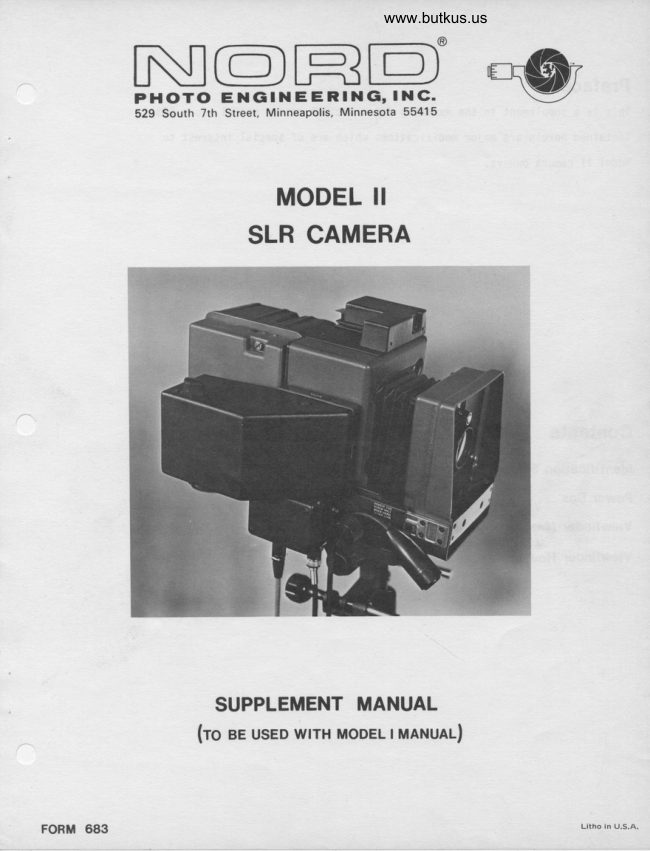
NORD Model II SLR Camera User manual
User manual for NORD Model II SLR Camera. 33 pages in English. Read the original PDF, download or print a copy without registration.
33 pagesEnglish4.9 MB PDF
Loading your manual…Open PDF directly
Document details
- Brand
- Nord
- Model / document
- NORD Model II SLR Camera
- Document type
- User manual
- Language
- English
- Pages
- 33
- File size
- 4.9 MB
- Category
- Film cameras
- Document date
- Not specified in catalog
Search available document text
Find a term, then jump to its page in the original PDF. Image-only pages may not be searchable; check the PDF for exact wording and diagrams.
Page 1 · Read text
www.butkus.us

                                                                        \-,/  N|@n=D',-\wPHCDTO ENGtNEERING, lNC.
            529 South 7th Street, Minneapolis, Minnesota 55415


             MODEL II
             SLR CAMERA


             SUPPLEMENT MANUAL
                   (ro ee usED wrrH MoDEL TMANUAL)


FORM 683
View original page 1Page 2 · Read text
Preface
This is a supplement to the existing Automatic SLR camera manual (Form 553).
Contained herein are major modifications which are of special interest to
Model II camera owners.


Contents                                                  page
ldentification System linstallationl                                   1-9
Power Box                                                              10-11
Viewf inder Mask linstallationl                                     12-13
Viewfinder Housing Assembly                                       14-15
View original page 2
Page 3 · Read text
www.butkus.us


                       ldentification System


                                                           I NTRODUCTION
 Image frames on roll film used with the Nord SLR Roll Camera can
be identified using either of two optional identification (1.0.)
systems.
Negative I.D.System allows information to be recorded in a space
between image frames. Information to be recorded on film is print-ed in a 3/B in X 2 1/4 in. space on a I.D.* card. Prior to exposurethis card is inserted into card holder (top of camera). Card infor-
mation is projected through a periscope onto the image frame during
expos ure  .
Pose I.D. System similiar to the negative I.D. system, but provides
individual pose identification. A pose character (A thru K ex-
cept I) and I. D. card information in a (3/B in. X 1 7lB in. space)*is projected through a periscope onto the image frame during ex-
posure. The pose characters advance automatically after each ex-
posure. Manual advance button is provided for re-orientation of
pose cnaracters.
Each fi lm size requires a matching periscope. If no identificationis necessary, then a "dummy" periscope must be used to prevent the
film from fogging.
Note: All lvlodel II cameras are wired for easy installation of I.D.
      systems. No soldering is required.


                           UNPAC KI NG

Irnediately upon shipment arrival, unpack the contents of the cartonand compare items received with the packing list, and the original
order. Inspect for any visible damage. If a claim is necessary,
file  it  immediately with the camier.
Caution: Do not Iift  camera by pose I.D. cover, viewfinder or front
          projection mounting bracket. Always lift  using both hands
          beneath main body of camera.

Tools required for I.D. System Installation

.Phi11ips screwdriver
.3/16 flat blade screwdriver
.Needle nose pliers
View original page 3Page 4 · Read text
Special Notes
 .Use I.D. equipped cameras with I.D. equipped magazines, and a
  peri scope.
 .Use non-I.D. cameras with non-I.D. magazines, and no periscope.
 .ln emergency cases, a non-I.D.magazine may be used with an I.D. camera. However, no periscope is to be used, otherwise part of
 the image will be blocked. No data can be recorded with this
  combi nati on.
 .An I.D. magazine (having a longer film advance) could be used
 with a non-I.D. camera. However, this combjnation wastes the
 space that would normally be filled with I.D. data.


            Negative I.D. Attachment Assembly

A. Disassembly of camera Prior to Installation.
    l.  Detach film magazine if  afixed to camera (see step E of
       Assembly section in manual and reverse the order of the
        steps).
  2. Pull out back plate and mirror assy. by removing the six
       phillips screws (see Parts Fig. 3 in rnanual ).  3. Lay back plate and mirror assy. so that the plate is face
        00wn.
      CAUTI0N: Handle back plate and mirror assy. with care.
                Avoid fingerprints on mimors and ground 91ass.
                     It is not necessary to disconnect the connector
                joining the main camera body with the back p1ate.
  4.  Lift off the cover plate from the top of the camera by
       first removing five screws. Leave the gasket in p1ace.
  The camera is now ready for the negative I.D. attachment. Check
   to make sure you have all the necessary parts.


                              2
View original page 4Page 6 · Read text
www.butkus.us


B. Installatlon of Negative I.D. Attachrcnt Systen.


                            Flg.l
      NEGATM I.D. ATTACHI'IENT ASSEI,IBLY. (Neccessary
       parts lqyed out before installation).
    Upon receiving the assembly, you will find the card holder
    conpletely assenbled. All that is shlpped loose are the screws
    necessary for fastening the card holder to the cannra, and the    lanp housing assembly (see the parts 'list).
     l.  Larp Housing assembly.
       a. Sllde the lamp housing assembly into the holder located
          next to the mirror assembly (see fig.2 ).  Insert so          that the bulbs are facing the mlrror.
           (Note: Do not pullnouslng by wlre leads.)
      b. Join the female connector on the lamp assembly with the
           male connector leading from the camera.       c.  Reinstal'l the back plate to the camera housing using the            six phillips scFews.
          Note: Before doing so, you nny ryant to change masks if                  the film size necessitates it  (see mask change                      'supplement).
           Caution: l'lhen reinsta'lling the camera back, be careful
                    of clearances between the bottom of the mirror
                      assembly and the printed circuit boards. Also
                    be sure that no plugs or wiring protrude into
                     the optical path.
View original page 6Page 7 · Read text
2.  Card Holder
       a. Position gasket over opeing in the camera top.
       b. Place assembly on top of gasket, Line up the holes in
          the card holder plate with those in the gasket and camera
            top.
       c. Insert the five screws shipoed loose with the attachment          (see Fig.1 for screw placement) and tighten just enough
         so as to make it  snuq.


                    www.butkus.us


                           Fig.2
                INSTALLING I.D. HOUSING ASSEMBLY.
C. Installing Negative I.D. Periscope,
    '1. Select the correct periscope for the film size used (size
        is marked on the periscope body).
   2.  Insert the periscope in the opening beneath the bronze lock-
        ing strip on the camera back plate, and push it upward until
        the strio locks with an audible click.
        For removal, gently lift  the strip while pulling downward
       on the periscope.

D. I.D. Card Format.
    Identification data is most conveniently written on a 3 x 5
    index card. The area reproduced on film is shown in the dia-
    grams below:


                          4
View original page 7Page 9 · Read text
Pose Counter Assembly

A.  Disassemblv Prior to Installation.
    (see step A of Negative I.D. installation)
B.  Installation of Pose Counter System.


                          Fls.3
       P0SE COUNTER ASSEBLY.  '. (Neccessary parts layed
       out before installatlon).
   Upon receiving the pose counter assembly, you trill flnd the   most parts have a'lready been assemb'led. (see the parts list
   on the folloving page).
    However, the cover is attached to the pose counter when shipped.
    Therefore, remove the cover (four screws and a switch collar)
   before installing to the camera. Use a needlenose pliers to
   unscrew the collar on the reset button.
     'l. Lamo Housino assemblv.
       (se! step g]l ot Hegitive I.D. installa'tion).
   2. Pose counter.
     Note: The pose counter should be handled with care, since
             certain parts cou'ld be easily damaged. Take note
             also of the four-pronged male connector 'located on
             the bottom of the counter base p1ate. Again, avoid
                  mi shandl  i ng .
                       6
View original page 9Page 10 · Read text
www.butkus.us


a.  Position the gasket over the lamp opening in the camera
     top.
b.  Guide the four-prong connector on the bottom of the pose
    counter assembly into the fernale plug-in-on.the camera
   top. Press dowit gently until the assembly base plate    seats on top of the camera.c.  Line-up the'holes in the base plate with those in the gas-
     ket.
    CAUTION: Be caveful not to twist the counter assembly
              while plugged into the camera top. This could
              damage the prongs on the connector.
 d.   Insert the four screws shipped loose. (see parts list)    Tighten just enough so as to make it  snug.
    Note: If you have access to an offset screwdriver, use              it to tighten the phillips screw beneath the
               sol enoi d .
 e.  Check to make sure the rachet mechanism is working prop-.                                                             (see- fig.a )    erly. To do so, press the rachet escapement     towards the solenoid several times. Observe if the rachet
    wheel turns to each consecutive letter as the excapement
    ls pressed each time.
 f.  Afix counter assembly cover by'lining up the four holes in
    the cover with the four hold-down bracket holes on the coun-
     ter assembly. Use the 2-56 x 3/16 screws, and tighten gently.
 9.  Replace the collar for the reset button.


     posE couNTER tsT$,iln rachet assembly).
View original page 10Page 11 · Read text
C. Instal  I i ng the  I .C. Peri scope.
    (see step C of Negative I.D. installation)
D. I.D. Card Fonnat.
    (see step D of Negative I.D. installation)
E. Using the Pose I.D. System.
    Before proceeding, be sure the camera is plugged in for power.
   1.  Install the proper size periscope (see step C of Negative
        I.D. installation).
   2. Make sure the rachet mechanism is working proper'ly. Push
        the reset button on the counter and release so that the
        rachet wheel is set on the letter A (as it appears through
        the view window in the counter cover). Now trigger the
       camera tripper several times to make sure the rachet wheel
        turns to a new letter for each exposure.
        (It is advised that you check the escapement arm on the rachet
'       assembly before the cover is replaced. The excapement arm
       on the lettenvheel gear teeth should seat firmly for each
        movement).
   3.  Insert an I.D. data card face down in the card slot on too
     .   of the camera.   4. Push the reset button and release until the letter A appears
       in the window.
   5. Make an exposure. A green indicator on the camera back will        light, indicating exposure of the data.


                         8
View original page 11Page 13 · Read text
Power Box
                                  '120 Volt.  . ..0051-031922
                           240 Volt....005l-031923

The power box (.|20 volt or 240 volt available) serves both as the power
control to the canera, and as a junction box.  Located belovl and adiacent
to the viewfinder, the bower box has seperate receptacles for each of the
following camera connections: Tripper cord, film magazine, and power cord'
Although assembled to the camera when shipped, the power box can be easily
removed for convenience of servicing.
A circuit breaker reset button is located on the front side of the box.

1, Power box removal.
    CAUTI0N: Disconnect the power from
    the outlet before proceeding.
    When removing the power box for service,
    or when changing power requirements,
    perform the following steps:
    a.  Remove the viewfinder for ease of
        working space (see Viewfinder section).
    b. Place the camera left side down (side
        opposite the viewfinder).
        Observe that the box is mounted to the
        bottom side of the side rail by means of
       a mounting bracket. Rennve the two
        screws from the bracket.
    c. A fema'le connector on the side of the
        power box plugs into a ma1e connector on
        the camera. Use care when removing the
        power box to avoid damaging the connector.
    d.  Gently lift  up on the side of the box
       where two receptacles are side by side.
       The power box connector is located near
        this side.
   e. While lifting the connector side of the
       box away from the camera, at the same
        time slide out the opposite side of the
        power box mounting bracket (L-shaped
        bracket feet) from under the hoid-downs                 Fis's
        (see Fig.5 ).                                     REMOVING POl.lER BOX.


                                     10
View original page 13Page 14 · Read text
www.butkus.us


2.  Replacing power box on camera.
   a. Slide bracket feet under the hold-downs while simultaneously aligning
       and lowering power box into the camera connector mate.
.  b. Push the connectors together until the box is tight against the cam-
       era Dooy.
    c.  Replace the two screws holding the power box bracket to the bottom side
       of the side rail.
When in doubt about a camera probiem, consult a local NORD representative for
assistance.


                                             11
View original page 14Page 15 · Read text
Viewflnder Mask


Changing viewfinder masks no longer necessitates removing the back plate
from the canera. Access is now possible through the vlewflnder base.
A viewfinder mask matching the film format must be installed at the ground
glass surface (except for-70rm, for which none is needed). .The size-of the
mask aperature must match the film format/image size. The table belor lists
the aperature sizes for ease of identifying nasks.
To install a mask:
l.  Select the corr€ct mask for the film size used from the table below.


                        Viewfinder mask aperature sizes
                       Full 70nm.....  llo mask required
          0051-013635 Ideal format.. 2-114 in. x 2-314 in.
          0051-013638 Split 7Om....1-314 in. x 2-3ltl in.          0051-013537 46nm...    I-3/4 in. x 2-314 in.          005]-013639 35nrn unperf... l-l/1 in. x 'l-3/4 in.          0051-013640 35nm perf..... l5/16 in. x l-7l16 in.

2. Remove the vielfinder.3. Remove the ttto screY{s from the field     'lens frame. Lift the lens assembly
    off of the vietvfinder base.
CAUTI0N: Be careful not to scratch or                                         -soil the lens. Grasp by the sides of
the 'lens.
                                ground4. Now you have access to the
    glass surface. The selected mask
    will rest on the frame of the ground
5. Graspgl ass. the mask by the attached knob.
                               selected    (see Fig.6 ).  Place the    mask so that one edge seats against                www.butkus.us
    the two locating posts opposite the
    nylon hold-in clip.


                                                       Flg.6
                                    12       INSTALLING VIEWFINDER  I.IASK.
View original page 15Page 16 · Read text
www.butkus.us


   CAUTI0N: Handle with care so as not to mark the ground glass surface.
6.  Press down the other edge so that it locks in under the c1ip. The mask
    is held in place also by the four locating posts, one at each corner of
    the mask.
7. Replace the field lens assembly. (No need to be concerned about reinstal'l-
    ing backwards.
8. Reattach the viewfinder.
   Note: Before replacing field lens, be sure no particles are on the ground
          glass surface.


                                      13
View original page 16Page 17 · Read text
Viewfinder Housing AssemblY
                                    (0051 -03.l 976)

The Viewfinder Housing Assembly for the Model II SLR camera is now easily
removed for fixing in any of three different positions. In addition,
each viewfinder housing is manufactured with a magnifier assembly already
attached.
To reposition the viewfinder housing:
l.  Depress one of the housing lock buttons with your thumb while at the
    same time gripping the top of the housing. This disengages one of
    the two housing locks from the viewfinder base slot.
2.  Still holding the one button in, lift  the disengaged side of the housing
    up and slide out the opposite locking wing from the base slot,(See figure
     bel ow )
3. When repositioning the housing, always slide one Iocking wing into its
    mated slot first and then depress the opposite button, and drop that
    side into place.
4.  Reiease thb button. The viewfinder housing is now locked into the base.


                                 Fis'7
             VIEWFINDER HOUSING ASSEMBLY.   (Removing viewfinder
            hood from base),

                                     14
View original page 17Page 19 · Read text
Find your part in the photos, take the
KEY NUMBER and look it up in the parts
Iist at the end of this section. Check
the name and order the quantity needed
by the N0RD part number. Do not order
parts by key numbers

     PARTS:          _'

Page No.       Parts Figure
    I      Parts Figure Reference
  ?     Front Body
  2     Rear Body
  3     Back Plate
  3     Back Plate & Mirror
  4     Negative Identification System
  4      Shutter
  5     Power Box
  5      Viewfinder
  6      Lenses
  6     120 Roll Film Adapter
  7      Cassette
  8      Drive
  B     Revolving Base
View original page 19Page 22 · Read text
www.butkus.us


     Parts Figure 3.  Back Plate


Parts Figure 4.  Back Plate & Mirror


                      3
View original page 22Page 23 · Read text
@e""y


Parts Figure 5. Negative ldentification System


          Parts Figure 6.  Shutter


                          4
View original page 23Page 24 · Read text
www.butkus.us

@ Eoattio/coleman
@
@c"t"tt
@@
@@
@@


@ tripper Cord assy
@@
@@

                   Parts Figure 7.  Power Box


                   Parts Figure B. Viewfinder
View original page 24Page 27 · Read text
OAseYWo Meterins cam
@4""y
            Parts Figure 12. Drive


         Parts Figure 13. Revolving Base
View original page 27Related documents and language editions
From the M. Butkus archive. Original publisher and archive notices are retained.
Check the model and edition against your equipment.
PDF verified 2026-10-10.