Film cameras
OPTIX Camera - Pt. 1 User manual
User manual for OPTIX Camera - Pt. 1. 58 pages in English. Read the original PDF, download or print a copy without registration.
58 pagesEnglish4.8 MB PDF
Loading your manual…Open PDF directly
Document details
- Brand
- Optix
- Model / document
- OPTIX Camera - Pt. 1
- Document type
- User manual
- Language
- English
- Pages
- 58
- File size
- 4.8 MB
- Category
- Film cameras
- Document date
- Not specified in catalog
Search available document text
Find a term, then jump to its page in the original PDF. Image-only pages may not be searchable; check the PDF for exact wording and diagrams.
Page 1 · Read text
www.butkus.us
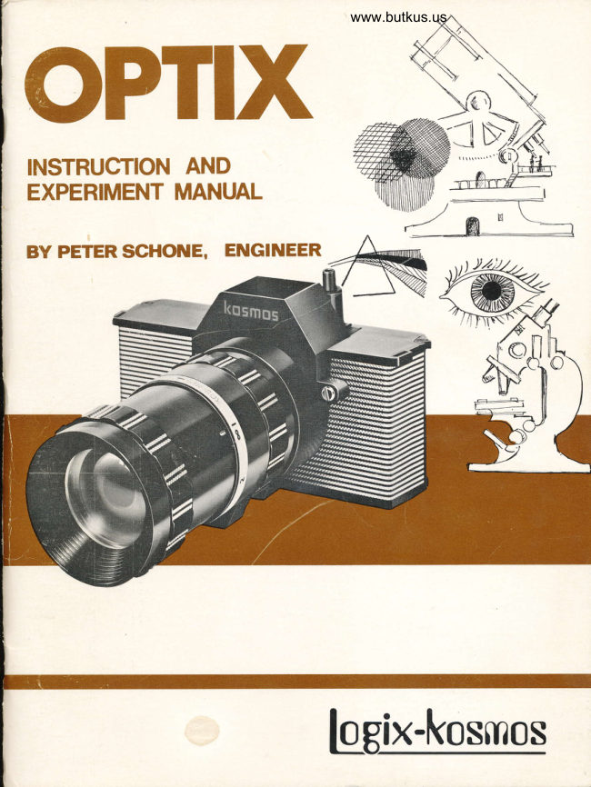
OPTIX
INSTRUCTION AND
EXPERIMENT MANUAL

BY PETER SCHONE, ENGINEER


                 loBix-kosmos
View original page 1Page 2 · Read text
'(.1
              165 66 67 68 69 72 73 74 7s77 78 76l|


                                                                                       52    @
  ffiffi# @@
  1. Objective Holding Ring.     28. Mirror  Support.              56. Laree Obturator I
 Z. Glass Mirrors  (Zl   .         29. Picture -Counting Dial.            ( 387, Hole tz/1l
  3. Glas s Sheet.                  30.  Dial S uppo rt.                 57. Large Obturator II
 4. Converging Lenses (5)   .    31. Half Shells (8)                       ( 387, Hote t6. 4/l    .
      ( Planar-Convex Igfi      .      32.  Daylight Obturator.           58. Srnall Obturator I
  5. Divergent Lehses (Zl       33. Red Filter.                             ( IBd, Hote 7 . 5/l    .
         ( Planar -Concave L86l      34. Green Filte r.                59. Srnall Obturator II
  6. Srnall Converging r,€os.    35. Yellow Filter.                        ( rs/, Hote Lodl ( zl  ..      ( Planar Convex I0/)    .      36. Blue Filter.                    60.  Slit Diaphragrn F ( l8l)    .
  7 . Large Converging Lens.    37, Transparent Mat Screen.    61. Converging Lensesl
      ( Bi-eonvex 37 .961  .         38.  Articulation Axis (Z)  .         Support Rings ( 4l   .
  8. Lar ge Dive rgent Len s.     39. Plastic Bolt.                  62.  Elastic Rubber Band.
      ( Convex-Concave Zl .9ll    40. Filrn Advancernent Pe g.     63.  Felt Band.
  9, Mat Piece of Glass.         4L. Irriage Guide,                 64. Bag with Cornponents
10. Lurninous Screen.            42. Support Bracket.             65 - 78.
 I l.  Flexible Mirror.             43. Nut.                          65. Obturation Ratchet.
LZ. Universal Adjusting         44. Filrn Advance rnent Wheel,   66. Large Traction Spring.
    C ornponent.                  45. Vis ion F rarne.                67.  Srnall Traction Springs ( Zl
13a. Microrneter.                 46.  Pedestal.                      59.  B olting Le ve r  .
13b. Photornete r.                 47. Square Conver ging Lens.    69. Expos ure Leve r.
L4. Front Lens Support.                ( Planar-Convex ZZ. 8    )  .  7 0. Wheel Catch.
I 5. Diaphragrn Suppo rt Ar c s .  48. Obje ctive Half- Shells ( Z)   71. Picture C ounting Catch.
16. Strap,                       49. Red Potas s ium Fe r ric       72. Mounting Screws ( 8)  .
17. Ey" Lens Support.             Cyanide  (III) K3 (Fe (CN)O ).   73. Strap Buttons ( Zl  .
18. Field Lens Support.        50.  Fe(III)   -Arnrnoniurn       74. Shutter Base.
19. Deflecting Prisrn.               Citrate.                     75. Pres sure Spring.
ZZ. Carnera Casitrg.             51. Pre s sure Sensitive           76. Shutte r Spring Support.
23. rrRapidrr Filrn Cassette.       Sheets ( Zl  .                 77" Shutte r Button.
24. Tele scopic Tube.           52. Camera Back Panel.         78. Shutte r Button Support.
25, Diaphragm Adjustrnent     53. Sliding Tubes ( 3)  .          79. Pierced Disk I(1 8y'Ho1e .8y'.1  .
    Ring.                        54. B"g with Cornponents        80. Pierced Disk II(18/HoIe 361  .26. Diaphragrn Ring.              55-63 and ?9-80.         Adh esive Strip.  Cut-Out Sheet.Z7 . Obturato r.                   55. Obturation Arcs  ( 4l   ,        Ins t ruction Manual.
View original page 2Page 5 · Read text
I.  HANDLING YOUR LENSES
    It is impossible to damage one of the parts throush   lack of experience,  if yo-u carefully  iii.r-rrrJ"-ri?"""t.
  From         the                start,                  you                        learn-the appropriate                                    way                                                      of hand-   ling all           the               parts.                       The,,follow!ng'parts                                       are                                               especially
   delicate:  rnat rnirror  #9, .and instrurnents #l3a and   l3b.  Their surfaces ,.ro"t ,r...""  b" ;;";h;;";i;;;""
  hands, as grease stains- or finger rnarks a."  i.rpJs"iUt"   to rernove. As fo.r the le-nses, yoo rnust only hoid them  by their edges. Be carefut ,roi io touch their surface!
    I_f you e-ver^drop a lens, consult the nCleaning Lenses
   f::"1   the Optix Kitil chapter at the end. of this manual.
  This last chapter also d6scribes how ro prepare an or-         smSt]                paint                   brush                                       ( you                                   rnust                                        cerLiniy  have one   l_t"1"trn your          paint              box) to                        clean                           your                                    lenses.
  You rnust under no circurnstances wipe or rub any lens  with a cloth, with- your fingers,  o" *ith  the palm,oi  your hand. The dust.you were trying to get  would scratch the polish of the surfa-...  "a  "fJ  "i,-
  of grease that would be invisible  at first,     "figni-i.y",*itt  time,  tarnish the lensr surface.           "oofE,
  Cleanliness in optics must truly be the first  cornmand_  rnent!   It is with good reason tiat the big optical lab_  oratories have cleansing'units at their J"t"L""u".  --
 In these laboratories,  the operators are dressed in special_overalls,                                          their                                      shoes,                   1.d rnust ihange street        dust is not introduced                                       into- the                                   working                                                 area."o-ifr", During particularly  delicate experirnent",             put on fine white gloves, and wear *t  lt.         "Ei"rrii"is                                             ""p".
 You donr t have to attire yourself s-o ceremoniously; how_ ever, when you are working with glue or when your'hands
 are greasy,  it would be a good idea to wash your hands        continuing                       with. youi                           experiments.                                                       d;;;;i=  *l:::,sclentlst,           experimenting                          with                                  prisrns,  lenses,                                                     reflectors and rnirrors,  as you are now ibout to do, finds his re_ y?.rd in clear pictures which he can view through-;.;"_ fully cleaned lenses and apparati.

 Z. IMAGES REFLECTED BY A MIRROR
 If you place a mirror  between two lines of a book text, you will  notice that the lines are reversed in the mirror, In reality,  a rnirror  reverses irnages in the following
way:  objects which are situated in front are placed tehind,
 and are thus upside down in appearance, as in the lineunder the word OVER.
                                                              {Can we see the lines back in their proper position  if weplace the rnirror  between lines whi.'ch are already opsia.down? If you try this by turning the book upside'd";;,                :i
it is seen that this works.  Howlver,  because we have
reversed the book, the line rnust be read from  righi toleft rather than in the usual way.

                                                                                                                                           i
                                                                                                                                                                                                                                                 "n'{
View original page 5Page 6 · Read text
www.butkus.us
Not only the words, but the letters too are written   f rorn
right to left.
You will also get ieversed writing   if you place the rnirror
Iaterally  along the edge of the text.  Then, and if the
rnirror  is placed on the right end of the text,  letters  sit-
uated far from the mirror   - on the left  - aPpear to the
rear,  or on the extrerne right in the rnirror  irnage.
Since the rnirror  is placed laterally,  there is a back to
front permutation, and a left to right permutation:  we
thus obtain rrreversed writingrr.
If you want to see how a rnirror  perrnutes or changes
back to  f ront,  simply place the rnirror  in front of you,
and draw a line with a pencil - a line drawn away frorn
you and towards the rnirror;  now, in the rnirror  you see
a pencil which is corning frorn the back and towards you.
If you draw a V in front of the rnirror,    it is seen as an
incornplete A in the rnirror.   T"y to write the word OVER
so that it can be read norrnally in the rnirror:   you will
notice that you rnust write your original word in reverse.

3. SECRET WRITING
If you place the rnirror  between the lines of a book, which
is upside down, you will no longer be able to read the
writing  in the rnirror,  even  if you are aware that it is
reversed writing,   This fact has been known since the
tirne of Leonardo Da Vinci  ( the farned physicist and
painter)  and exploited by scientists, who wished to write
their results of their research in a writing which only
they could understand.
You too can cornrrrunicate in a similar  secret writing.
You rnight argue that it would be too difficult,  to write
letters  in reverse.  Well , not if you know a little  trickl
Take an ordinary piece of carbon PaPer ( with the carbon
side up) , and place two thin sheets of paper on top of
this carbon paper. On the top sheet, write norrnally
with a pen or pencil, and on the back of the bottom sheet
you will  find that your writing has been reversed.
When you wish to read the letter,  you only have to place
 it in front of a rnirror  in order to read  it norrnally.

4. SELF-PORTRAIT OR NOT?
 If you stand in front of a rnirror  and rub your right eye
with your right hand, what is your irnage doing in the
 rnirror?    It is obviously rubbing the eye which is located
 exactly in front of your right eye.   If this were not a
 rnirror  irnage, but a real person standing behind a pane
 of glass, then that person would have to be rubbing his
 left eye in order to irnitate exactly your rnirror  irnage.
In a later experirnent, you will see what rnust be done
 for the rnirror  irnage not to be reversed.  For the mom-
 ent you can hardly imagine this,  but on the other hand,
 you will  certainly be able to tell which of the three rnen
 in the sketch painted his own portrait and which had his
done by another artist.
                                                                    5
View original page 6Page 7 · Read text
Generally, a painter holds his brush in his right hano.
                                  But what happens when the painter is left-handed? This
                                            is very simple:    if we can spot any buttons or button
                                  holes on a shirt,  a jacket, or a coat' we can decipher
                                whether we are dealing with a rnirror  irnage or not -
                                       sirnply by observing the position of these objects.

                                       5. OBSERVING WITI{OUT BEING NOTICED
                        A detective who has been inforrned of a planned robbery
                                         in a seashore hotell s garage, wanting to capture the
                                      criminals,  would not place himself in front of the garage
                               and overtly observe the door.   If he did this, the robbers
                               would certainly be suspicious and postpone their plans
                                         for another day.  But,  if sorrleone at a certain distance
                                from the garage was looking out over the open sea with
                             a telescope, aPParently viewing sail boats, then the
                                 robbers would believe thernselves to be totally unobserved.
                               They would not know ( thanks to a reflecting rnirror
                                   placed in  f ront of the telescope),  that the image of the
                                   garage door was reflected to the detectiver s eye.
                             You can build such a device  if you ir-rsert the three sliding
                                   tubes #53 into each other, and then place thern in front of                                      vision frarne #45, which would serve as an trairning frarnerr'
                           On this rraiming frametr you pLace glass reflector  #2
                                    attached with three pieces of adhesive tape, as seen in
                                     the diagrarn to the left.

                                       6. INVERSING THE IMAGE A SECOND TIME
                                       In the event that sorneone were to place a sign on the door
                                       of the garage which the detective frorn the previous chap-
                                          ter was observing with his rrdeflectionrr instrurnent,  the
                                         Digitally                                         signed                                           by Mike                                                      Butkus    detective would find hirnself in difficulty'   His rnirror                               DN: cn=Mike                                                 Butkus,                                                 o=Butkus                                                                               But a                                                                                 only.                                                       reversed                                                                           writing                                                      sign in                               camera                                        manuals,                                                  ou=butkus.org,                                     show the                               wouldMike Butkus                                 email=mike@butkus.org,                                                c=US                                                                                      problerns.                                                                         these                                             how                                           knows                                                                   to overcorrre                                       real detective                                    Date: 2021.08.01                                                    23:06:59                                                                    -04'00'
                           He would simply take a second reflector,  through which
                                 he would be able to perceive the reflected irnage of the
                                                  first  reflector.  Because the objects which are inversed
                                by the first  reflection are inversed again by the second
                                         reflection,  the image therefore aPPears in its norrnal
                                       position.
                             Our detective consequently, would place a second re-
                                          flector  at the opening of his instrurnent, as shown in the
                                     diagrarn.  This rrdouble reflectorrrtelescope has the
                                   advantage that our detective could now turn his back on
                                                  tJre object he is observing.

                                       7. A SURPRISE RESULT
                                  This is sornething that we do not see daily, and that does
                                   not go by unnoticed!  Irnagine sorneone looking through
                               an instrurnent placed at an angle in front of his face!
                                  This is why our detective would think that he should hold
                                     the instrurnent verticallv  and above his head, and look
View original page 7Page 8 · Read text
www.butkus.us
                                        through the lower reflector,  thus seeing the area behind
                                            hirn a-nd over his head. Holding his instrurnent this way,
                                       the detective would be able to stand behind a wall and
                                    remain unseen.
                                       But whatr s happening? Now everything is once again
                                       upside down!

                                            8. HOW ARE RAYS DEFLECTED?
                                  The detective draws hirnself a diagram which shows
                                  him how the rays are deviated by the reflectors'
                                               First  of all, he draws a diagram shwoing how light from
                                   an image is deflected by a single rnirror  towards the
                                                  right.  The light corning frorn the sign with the letter.s
                                 L?nd R is dellected onio a screen' which shows what
                                          the eye would see if  it were the screen'
                                      Here, we can clearly see how the rays comingJrom L
                                   and Ii cross each other and change sides after being
                                           deflected by the rnirror,  A second perrnutatigl  ( or
                                    change) is produced with two rnirrors   - the sides are
                                        again exchanged bY the new mirror.
                                       Next, our detective rnakes a second diagrarn showing
                                how the rays are deviated to different heights by two
                                            mirrors.  We easily notice how the instrument used by
                                          the detective ( chapter ?) gives reversed irnages  if  it
                                                   is held in a verticil  position. We realize that what'the
                                            detective had in rnind to improve his instrurnent was to
                                            deflect the light as in a subrnarine periscope'  Now,                                                  'after                                             having turned the bottorn rnirror,  the detective
                                               really can rnake observations over a wall without
                                        being noticed. He can also, look at the spectators
                                       behind hirn while in the midst of a crowd watching a
                                              football game.  This type of periscope shows norrnal
                                          pictures even if  it is held in a lateral  position.

                                             g. ANGULAR MIRRORS
                               Two rnirrors,  whose edges touch, while they are oblique
                                             to one another, are termed Angular Mirrors.   In each
                                             of these rnirrors  you see the reflected irnage of the
                                            other, and naturally,  the inversed image of anything
                                             that is reflected in the other mirror.
                                     Place the Angular Mirror  behind the word OVER, printed
                                        upside down. Having done this, you first  see the word
                           ABER on the left and right,  in reversed letters.  On
                                        the right mirror,  the beginning of the word is at the
                                       lowest point; and on the left one, the beginning of the
                                  word is at the top-most point.  At the center, you see
                                           the rnirrors  reflecting one another, as well as the in-
                                     versed images of the word.   If you have adjusted the
                                               rnirrors  correctly,    it is astonishing that these inverted,
                                            reflected images end up as one word - OVER -  normally
                                            written and in the correct  posttion.

lt
View original page 8Page 9 · Read text
10. THE IMAGE PRODUCED BY THE INVERTING
    MIRROR
  If you have a dresser or washroorn rnirror  at horne on
 which there is a triple  mirror  with adjustable sides, you
 can then place one of the side rnirrors.on  a slant re-
 lative to the central rnirror.     If you do not own one of
 these, all you need is another mirror  (as large as
 possible), which you can hold next to any wall rnirror.
 By looking into the corner of the rnirror,  you will  see
 a reflected irnage, cornposed of two images which are
 inverted,  reflectbd, and re-united,  co.tslqoently dis-
 playing a normal image.
  If yo.u now lift  your right hand while holding a comb, the rrinverted reflected irnagerr will not lift  the hand
 which is irnrnediately in {ront of your right hand., but
 the one which faces your left hand - just as if you were
 not facing a rnirror  irnage, but rather a living person
 who is also lifting the right hand as you are doing....
 You are now seeing yourself as others see you. An
 Angular Mirror  then solves the problern we encount-
 ered in chapter 4.

  II.  AN EYE THAT CONSTANTLY WATCHES YOU
 AIl angular mirrors,   includin-g the one you can assernble
with two glass reflectors #2, possess one peculiarity:
 if with one eye you watch the point of contatt of the two
 rnirrors,  the reflection will always be such that the eye
 will be watching you - whether you are gazing into the
Angular Mirror,  or either of the side rnirrors.
Of cour-se, for you to observe this characteristic,  you
rnust adjust the rnirrors  at a very precise oblique
angle to one another. However, this is not very difficult!
Sirnply hold thern so that the contacting edge passes
exactly through the reflected irnage of the pupll of the
eye, and each rnirror  contains half the eye.  This way,
you can see the whole eye between the tw-o of them.   If
you then liold the rnirrors  firrnly  in place, foo will  beable to move your head in eitherra lateral or horizontal
direction;  the eye will always remain behind the con-
tacting edges of the two rnirrors.  Do you want to know
how this is possible? Very simply: an Angular Mirror
sends back each bearn of light that strikes  it  ( and pre-
cisely in the direction frorn which it arrives)   , as iongas it cornes frorn a horizontal direction and not on a
slant,  The next two chapters will show you exactly
why this is so.

IZ, HOW IS LIGHT REFLECTED BY A MIRROR?
_We already know that a mirror  reflects light r3ys.
Now we wish to know in what manner, or in wfrilfr ai-
rection this occurs.   If you draw a line with a ruler,
the rnirror  irnage of this line seems to run backwards_
As soon as you turn the rnirror  slightly sideways, the
View original page 9Page 10 · Read text
www.butkus.us                      line appears to break when it reaches the plane of the
                   mirror  and pursues a different direction.
                 Place a mirror  on the thick black line in the drawing
                on the left.    It is rernarkable that lines oblique to one
                   another extend thernselves without breaks in their re-
                    flected irnage s !
                    Starting near the mirror,  go over the line ending in an
                 arrowhead, and go right up to the arrowhead,
                               If, while doing this you can look sideways in the rnirtor,
                  you will see how the pencilr s rnovernent is reflected in
                    the rnir-ror.  The actual direction in which you are
                   rnoving your pencil , shows the actual rnovernent of the
                   entering light ray, once it has been obliquely deflected
                 by the rnirror.
               You see then, that a line directed towards the rnirror
                 always continues in a straight line in the reflected irnage
                          ( single arrow)  , which is equal to the angle forrned by
                   the arrowed line that leaves the surface of the rnirror
                            ( double arrow)  A ball, kicked at an angle against a
                      wall,  also bounces in the opposite direction and at the
                    sarne angle with which it originally  hit the wal1.w                The law that states that these two angles (the one de-
                  noted by a single arrow in the diagrarn, and the one
                  denoted by a double arrow)  are equal, is outlined for
                 you in greater detail in chapter 33.   It holds true for
                 any light ray hitting a reflecting surface ( scientists
                  say th;t this ray is reflected)  , no rnatter  if the ray
                      hits the surface at a srnall angle ( a) or at a greater
                 one ( b) .   If  it hits the rnirror  directly  frorn the front
                                   it is thrown back along its own path.
                               If you place a rnirror  on the thick black line on the
                    drawirlg on the left,  you will see how each line is re-
                     flected as a straight line in the rnirror.  You can tell
                 which line is which by running your pencil along thern
                  and, at the sarne time, watching the mirror'abt\             You will then notice that the trajectory  of the ray is
                     reversible.  You see the li'ne drawn as an incident ray
                            ( the angle rnarked by a single arrow in the diagrarn
                  above) f just as clearly as the extension of the -refl'ec -
                      tion angle ( the one denoted by a double arrow in the
                    sarne diagrarn in the reflected irnage)  ,   if you look
                       trbehindrr in the rnirror  along the angle of reflection'

                   13. 14/HEN LIGHT FALLS INTO THE ANGULAR MIRROR
                     In this diagrarn you can see how the light rays falling
                      into an Angular Mirror,  leave in exactly the sarne
                     direction by which they carne' When the rays fall
                     obliquely, the angle they forrn with the first  surface
                     of thl  rnirror  is small , and the one they lorrn with tle
                  second surface is greater.  As the bearn straightens
                     out and hits the mirror  rrlore directly,  the angle on the
                            first  rnirror  becornes greater, and the one in the second
View original page 10Page 11 · Read text
bepornes srnaller,  The bold lines show the beams
                                        hiitting the rnirror  straight on. When this happens, all                                 four angles are equal.

                               14, A THREE MIRROR REFLECTOR
                     A reflector  rnust send back light received in the sarne
                                  direction frorn which it carne; a driver  of a car,  seated
                                    directly  behind the headlights, is therefore reached by
                                 the light reflected by the reflector  of the car ahead.
                              This is the desired effect.
                              'Would the Angular Mirror  of chapter  ll rnake a good.
                                  reflector?  After  all,   it does return rays in the direc-
                                   tion frorn which they corne ( as you saw in chapter 13)  .
                                                   If you point the Angular Mirror  in your friendis  direction
                                                   ( who is rneanwhile pointing a flashlight at it)  , you will                            soon realise that the rnirror  works, only if  it is held
                                exactly at your friendr s height.
                                                   If you turn the rnirror  so that the two side rnirrors  are
                                pointed at each other, a difference in the height and
                                 position of your friend would not rnatter; butLn the
                               other hand, he wou_ld not see the light bearns being
                                 reflected  - unless hisposition was exactly adjustJd to
                                the rnirror.
                              fhe best idea is to transform the Angular Mirror,   so
                                  that it possesses the characteristics  of this type of
                                     rnirror  and also those of rnirrors  set side by Jide and
                           on top of each other.  This is achieved by providing
                                                        it with a reflecting surface.  To do this,  simply place
                                                        it on flexible mirror   #11.
                              This cornbination of 'rnirrors   ( cornposed of three
                                mirrors  placed vertically on top of each other ),  is                                called a triple  mirror.   You rnay prove that this triple
                                     rnirror  throws back all the light which hits  it obliquely,
                               with a visual test:    if you glance into the triple  rnirror,
                          so that the pupil of your eye appears to be piaced be-
                              hind the corner where the three rnirrors  rneet, you
                            can rnove your head in any direction without this eye
                             ever changing place.  Once again, you can use this
                             phenornenon in adjusting the mirrors.   Just before the
                                   rnirrors  are perfectly in place, you notice six eyes
                             forming a crown set about the central point; after a
                                    slight re-adjustrnent of the rnirrors,  the crown will
                              becorne one single eye.
                                                  If you cornpare this irnage with the one we previously
                               obtained in the Angular Mirror,  you will  rrotic" that in
                                    this case the eyebrow is below the eye. Top and bottom
                             are thus perrnuted in the triple  rnirror.     If you observe
                                the irnage reversed, the top and bottorn then appear
                                    in the correct position, but the sides are then dis-
                              placed,  In any case, you cannot rnake this observation
                               with the eye, for, when you perforrn the experirnent
                                    in which you view the image reversed, youi eye is also
                             then reversed.  This experirnent can only be done wittr
                         a sheet of paper on the corner of which you inscribe,
t0
                                                                                                                                                                                                                                                                                                                                                                             II

                                                                                                                                J
View original page 11Page 12 · Read text
www.butkus.us
                                          for instance, the word OVEFL  If you hold this PaPer
                                    upside down near your eye, you will see the word
                         OVER in the mirror  inverted'
                                    Seeing that one mirror  grye: an inverted image and
                                two rriirrors  give a normal irnage,  it is not too surp-
                                          rising that three rnirrors  produce an inverted irnage'
                                 For use as a reflector,   it is unirnportant that the rays
                                   are sent back inverted.  aw
                                                            If you observe a reflector  carefully,  Yotr will-notice.
                                                                        iijiit     .o""i"t"   of small shining triangular  cells'  Each
                                        of these cells is nothing rnore than a triple  rnirror.
                                      consisting of three triangular sides of cornbined'mirrors
                               Most oftei however, the rnirrorsr  surfaces cannot be                                   touched for they are located behind a smooth and trans-
                                          ;;;;;i;";face'made      of glass or of svnthetic matter'
                           On July Zl' 1969, the Arnerican astronauts who landed on
                                    the moon left behind a laser  reflector.  The reflector,
                                   very rnuch like the reflector we have discussed in this
                                      chaptet,  is being used by scientists to bounce laser light
                               beahs frorn the surface of the mrron back to earth' Even
                                                                   if the reflector  is not pointed directly  at the earth,  it
                                                will  reflect the light to its source.

                                    15. A KALEIDOSCOPE
                                                            If you once again combine the two glass mirrors'
                                                    ."i[i"g  a si.tt--ple Angular Mirror,    ( as you learned to
                                do in Jhapter 9) , yoo can then pl1,c-e a mounting screw
                                   #tZ U"*rien them,  This screw will be reflected three                                                       iirrr"".  We will then see four adjoining screws arranged                                                                                                     the   'A,'A            ir,   ."o*n  shape.  If you enlarge the angle which
                                 two" rnirrors  forrn,  you will  see only three screws -    IAN [Kil       the screw itself and twoof its reflections'
                                                             If, however, you reduce the angle, more inverted
                                   screws will appear, and a rnagnificent drawing will     -
                                            result.  When yoo at.  finished this experirnent'  donr t
                                   throw the screw aw?f r as you will need it later'
                               The instrument with which reflected irnages are assernbled
                                         to form drawi.ngs is called attkaleidoscoperr'   If you
                                   place a nurnber of rnulti-coloured PaPers, in randorn,
                                                itJu.,   between the mirrors,  a geornetric drawing which
                                  can co.tstantly be rnodified ( if you ruffle the bits of
                                       pape r)  wiII aPPear.
il                                   16. A DRAWING INSTRUMENT
                                                             If you stand in front of the window looking down on-glass
                                                       strl.t  #3, (which you should lean towards the wi'ndow)   '                                    you will be able to see everything that is going on in
                                            iront of the window, just as if you were using a mirror'
                                    This segrnent of glass has a polished surface, and is
                                           th,refoie  smooth, so that it reflects  aII the light rays'rl                                     Furtherrnore,   it is also transParent, so that the light
                                          iay"  fto.rr a sheet of paper, (which you shoul-d P1":"
                                                     o.ri..   it)  , can also rlach  yorrr eyes'   If you hold the
                                                                                                                                                                                            ll
View original page 12Page 13 · Read text
glass sheet very near your eyer fou should be able to
                               reproduce on the paper, outlines of objects reflected
                                     in the glass sheet. However, you will soon realize
                                  that this procedure cannot succeed for three reasons:
                                       Firstly,  the reflected images shift relative to the tip
                                  of a pencil held near the paper.  This occurs even  ii
                            you modify the inclination of the mirror  only slightly.
                             Secondly, the reflected irnage is usually so brigfit
                                  that the pencil tip becornes invisible.   Thirdly,  since
                                 the irnages are reversed when they come into view.
                                they present an inverted drawing when  it is turned
                                 around.
                       Why abandon our experirnents already, just because
                                  of a drawing instrument?  Actually,   it  ii  possible to
                          remedy these three unfavourable characteristics  bv
                            making use of a few rrrore trtricks of the tra6"rr.         '

                                      I7.  IMPROVING THE DRAWING INSTRUMENT


                                                                                                                                                                                                                                                                                                                                                                                                                                                                                                                                                                                                                        'jl                        To irnprove the drawing instrurnent, you must deviate
                                       light frorn the window by using rnirror  #2, before the
                                       light goes through glass sheet #3.  In other words,
                            send it onto the glass sheet via a detour - by having.it
                                        hit the rnirror  first.  To accornplish  this, yoo                                hold the mirror  with its reflecting side towards-o"ithe
                           window, so that the light beams are repelled towards
                                the floor with only srnall angles of incidence and re-
                                     flection.   You then direct these beams towards vour
                             eye with the help of the glass sheet, which is held at
                           an oblique angle in front of the mirror.     It does not
                                  rnatter  if the bearns of light pass through the glass
                              during their trajectory from the window to thJ mirror.

                                                                                                                                                                                                                                                                                                                                                                                                         :                          So that you can easily rnaintain the glass sheet and the
                                                                                                                                                                                                                                                                                                                                                   ,j                                mirror  at the correct angles, we have drawn a mirror
                             support on the cut-out sheet.
                                    A,{ter having cut out this support, you put a thin layer
                                  of glue on one side of the contour"-opor which the edges
                                 of the glass sheet and the mirror  must be stuck.  piess
                              these firrnly  into place,  ( the rnirror,  with the reflec-
          www.butkus.us            ting surface turned towards the glass .sheet)   Then,
                               wait until they are dry.   Finally,  apply sorne glue to
                                       the- o-ppgsite edges of the mirror  arrd tir. glass sheet,
                            and fold the other side of the support whiih  is  still
                                   free.  Press until this section ii  al so dry.
                          The diagrarn on the left shows you the completed draw-
                               ing instrurnent ready for use. you can recbgnize the
                             gpper part of the new instrument by the turned down
                                  flap of the central piece.  you must observe the gtass
                              sheet from above.
                           Are you asking yourself how this new instrurnent
                               eliminates the disadvantages, encountered in the pre-
                              ceding chapter? The first  disadvantage is now co-rrected
                            by the double reflection;  therefore, a rnodification of
                               the inclination,  in which the instrument is held, can no
l2
View original page 13Page 14 · Read text
www.butkus.us
longer have any effect on the examined image. As long
as the angle between the glass sheet and the rnirror
rernains unchanged ( and these two have now been glued)  ,
the bearn of incident light forms relatively  to the beam
of reflecting light.  This provides an angle which is
invariable, and upon which the inclination of the drawing
apparatus has no influence.  Only a horizontal  ( or
lateral)  rnotion would cause the irnage to shift.
The over-bright  quality of the irnages viewed through
the drawing apparatus is now irnproved by the glass
sheet - which deflects certain bearns so that they
neve r ente r the ins trument.    It a1s o abs orbs othe r
bearns, with the same result.
Finally,  the images are in their normal position and
level, due to this double reflection phenornenon.t

18. A MIRRORIS THICKNESS
You now know that polished, shiny, surfaces reflect
light.  However, sornetirnesr fou may not be sure
whether a certain object reflects because its surface
is naturally shiny, or because  it consists of a glass with
a layer of foil on its back surface.  You rnight also want
to know the thickness of a certain frarned mirror
without having to rernove the frame.  This can be done
easily.  Just touch the glistening surface with the tip
of your pencil.  You can easily notice whether the tip
is in contact with its reflected irnage or not.   If  it is
not in contact, this is because the shiny surface is
behind a transparent coating, such as a pane of g1ass.
Try this out with glass reflector  #2.
Flexible mirror  #11, on the other hand, has a polished
rnetallic surface.  Here the object and its reflection,
touch when the object is brought up to the mirror.
This  I touchingr is a valid criterion  for  all reflecting
s urface s.
You might think that the space between the tip of your
pencil and the reflected image in a pane of glass with
a layer  of foil behind it,  is equal to twice the thickness
of the pane of glass ( ie: the thickness of the glass
added to the thickness of its reflected image) .  This
is not so. A pane of glass always seerns thinner when
we look through  it.  We will  later exarnine the meaning
behind this optical illusion.  A11 wetll  say for now, is
that the distance between the tip of the pencil and its
reflection  is only slightly greater than the thickness
of the pane of glass, measured when the tip touches
the pane of glass.

19. A CURVED MIRROR
Place flexible mirror  #tt,  1 with its polished, glisten-
ing, surface face up) on sliding tube #53 and press its
edges down. You then have a curved mirror.      lf you take
a look at yourself in it,  your face will seern stretched
                                                               l3
View original page 14Page 15 · Read text
and narrow.  In this type of rnirror,   all objects appear
                             narrower than they really are.   Its advantage is that
                         more objects can be seen in  it at once than in a flat
                                      rnirror.  A curved rnirror  directs light rays ( captured   uffi             frorn the sides) towards the viewer standing in  f ront
    ----N<4L*          Iiquely,of it.  In relativethis typetoofthernirror,axis aboutall objectswhich theappearrnirrorob- is                              curved.  They also appear rnore cornpressed.   '
                          The rnirror  rnust be curved evenly for objects to be
                           narrowed proportionately.   Its bent edges are in fact,
                                the arcs of a circle.  Such rrreduction rnirrorsrr are
                            used on cars as rear-view  rnirrors.   Their field of
                                     vj.sion is rnuch greater than that of flat rnirrors.

              www.butkus.us
                           ZO. A CONCAVE MIRROR
                      Now take fl.exible rnirror  #11 again and place  it over l/1l\lW                                   sliding tube #53, Bend  it so that the shiny surface is
                                                                                 I          on the interior.     If you place any object near enough        I nn               to this arched rnirror,  the object will  seern larger
                               than it really  is.   If you hold the tip of your pencil
                              close to the rnirror,    it will appear laterally  stretched  ryN              out,
                      How is this effect in the reflected irnage produced?
                          The diagram on the left shows how the rays leaving
               b         frorn points A and B rneet at a relatively narrow angle
                           These rays are drawn with dashes. The rays which
                               leave frorn points A and B ( indicated by a solid line)
                                 rneet at a wider angle, since the mirror  is curved.
                               Therefore,  the distance between A and B will  seerrr
                              rnuch greater in the latter case, than in direct ob-
                                 servation, A real concave rnirror   - for exarnple a
                                   circular  shaving rnirror   - is evenly curved on all
                                sides.  Thus it is a fraction of the interior  of a re-
                                   flecting sphere.

                             ZL, A CONCAVE MIRROR AS A LAMP REFLECTOR
                                                   If you want the light from a larnp to shine in only one
                                   direction,  you can obviously place a rnirror  behind the
                                  larnp.  In this way, the light rays, which are otherwise
                                    lost in every direction,  are projected in the desired
                                   direction.
                                                   If the larnp is placed in front of a flat rnirror,    ( as in
                              the diagrarn on the left)  , the rays are  still  scattered.
                                                   If, on the other hand, the lamp is placed in front of aZfiMM    concave mirror,  the rays cluster together.   If the                             curve of the rnirror  is circular,  the best concentration
                                  of rays is obtained when the larnp,is placed at a dis-
                              tance from the surface equal to l/2 radius of the sphere
                                  of this surface.  The rays do not leave the surface of
                                the rnirror  in parallel lines.  Rays which aie directed
                                  farther  out and into the rnirror,   cluster together, so
                                  that the group becornes narrower.  The further  out
                              the rays are projected frorn their source onto the sur-

l4
View original page 15Page 16 · Read text
www.butkus.us
face of the mirror,  the closer their meeting point
will be to the rnirror.   After the rays have rnet, they
disperse again.
If a projector has to throw light at a great distance,
the rays involved should be as parallel as possible.
The way to achieve this,  is to use a concave rnirror,
the edge of which is not as curved as the central part.
This is called a parabolical rnirror,  and is used in
car headlights.

22. MIRRORS WHICH MELT METAL
This seems unbelievable, but itr s true!  Unfortun-
ately we cannot dernonstrate  it with the three mirfors
that we have in our Optix kit,    If we listen to stories
of olden tirnes, we find that rnirrors were once used
in battle to burn the sails of enerny ships. No doubt
you wonder how this was possible!
Take flexible rnirror  #11 ( which has been curved into
a concave shape) and direct  its shiny side towards the
window or a lamp.  You will be able to see a bright
spot forrned, after which the rays disperse.  The rays
merge when they fall parallel to one another onto a
concave rnirror.     If the rays enter a parabolical rnirror
directly by the front,  they unite at a single point.
In aiming this type of rnirror  at the sun, all the rays
which hit the rnirror,  unite at a eertain point.  This
one point is very hot, because solar heat rays also
corne together at this point. We can easily light rnat-
ches with srnall parabolical rnirrors   if we hold the
inflarnmable end at the raysr point of convergence.
If the surface size of a mirror  directed towards the
sun is 1,000 tirnes that of the spot of light produced,
that spot then receives I,000 tirnes the arnount of heat
it would norrnally receive.  We would obtain intense
heat if a concave rnirror  several rneters in diarneter
were used.
Try to irnagine thousands of people seated at a football
game.   If each of these spectators had a large wall
mirror,  and all of thern directed their rnirrors  at the
sarrre spot, the grass at that spot would gertainly burn
irnrne diately  !
In the Mediterranean area, where the sun is very hot,
such a mirror  actually exists!   It consists of a great
nurnber of srnall rnirrors  which can be turned towards
the sun. Even though the diarneter of this mirror  is
not as great as that of a football field,  rnetal bars rnelt
instantly  if they are held at the point where the rays
conve rge.

 23. CHECKING THE MIRROR
You already know how the images reflected frorn a
                                                               I5
View original page 16Page 17 · Read text
curved rnirror  differ from those produced by a flat
                                      rnirror.  Now you are about to find out how undulated
                                mirrors   ( rnirrors  with uneven shiny surfaces) , give
                                 distorted reflected images, We say that such rnirrors                                             ttlierr. Do our glass reflectors  tell the tltruthrt?  If
                              you look carefully at glass rnirrors  #2, you will  not
                                spot any defects, for they give perfectly good irnages.
                           However, in reality,  there are very few perfectly
                             shaped glass pa-nes - whether they be window panes
                                or panes used to'cover mirrors.   However, usually theee
                                 defects are so insignificant  that we must take a very close
                               look to be able to discern thern at all.  How can we check                                  'our                                  glass reflectors  for whatever defects they rnight
                               have ?
                           Take one of these reflectors and simply place  it flat in
                                   front of you at a footts distance.
                            Then, extend your arm while holding a pencil before
                                the mirror,  so that you can see the pencilt s reflected
                                irnage when you look flat along the mirror.     If there
                                       is an undulation  ( or wavy motion) then the straight
                                pencil will   seerrr warped, and will appear to be rnoving
                                                        if you change the position of either the pencil or the @N             mirror.   To spot other undulations (those running in
                                   different directions along the surface of the rnirror)     ,
                                  sirnply check the mirror  frorn different  sides.

                              24, THE REFLECTOR TUNNEL
                        When you are not using your drawing instrurnent,
                               rernove the reflector  frorn  it.  Check it as we have
                                outlined in the previous chapter.   If the two rnirrors
                             are of different quality, keep the best one ( the one in
                           which the central part is better)   You will need it
                                    later  for the photographic apparatus, so be careful                                                    'ri1i
                               with  it!  On the other, draw two lines   f rorn its corners,                                Yt!                            so that they intersect at the center. Do this on the back                            I
                                  of the mirror  and scratch the foil-coating away at the                                                'l
                                 intersection point of the two lines.  Use a sharp point                       {                                  to obtain a hole with a Z rnm. diarneter.  Place both #Z
                                  reflectors  facing one another, and to help you keep
                                thern in the correct position, place the half-shell  #31
                             between thern. You can tie this part on with rubber
                            bpnd #52 wrapped around twice.  Each surface alter-
                               nately reflects that which is present in the other sur-
                                face.  This happens an infinite nurnber of times, and
                                                                                                                                                                                                                                                                                                                     I  tW          through the hole you have rnade, you can observe this.                                                                                                                                                                                                                                                                                                                                                                                                                                                                                                                         I.i
                                                                                                J
                              25. THE HIDDEN COIN
                           Very  little  light can penetrate a tall,  dark, and narrow
                               tube,  This is why your friend would not be able to
                                distinguish which coin has been placed on the table,
                                                       if you have covered  it with a long tube consisting of
                              three sliding tubes #53 and vision f.rarne #45.  The
                        more he bends over the tube, the less he can see the
                                 coin.  This is because his shadows are also penetra-
                                                                                                                                                                                                                                                                                                                                                                                                                                                                                .                                  ting the tube.  Bring the tube nearer to the window,
r6
View original page 17Page 18 · Read text
www.butkus.us
 so that the light which is reflected frorn your friendr s
 face, can light up the tubet s interior.     If he wishes
 to let the light penetrate the tube, heril think that he
 must remove his head frorn the opening. Then, of
 course, he will no longer be able to look inside!
 You, on the other hand, knowing how to use mirrors,
 know what to do. The rnirror  with the hole laterally
 directs light into the tube. However, tour eys, peer- ing through the hole, can follow the light down to the
 coin.   If the hole is a little  srnall ( seeing                                              -over'theas you must hold this mirror  at an angle)  , then look          upper
 edge of the rnirror  and shift  it a little  to the side,  yoo
 will then notice the coin, brilliantly  flooded with light.

 26. THE BENT SPOON
 Surely you have noticed how a spoon or a straw appears
 broken or bent when you place  il in a glass filled;ith
 wate r.
You can continue these observations with a large bowl
 filled with water.  An object placed at the bottolm of
 the bowl appears to rise from the bottom of the bowl,
    your eyes approach the edges of the bowl and as you -aslook flatly along the surface of the warer,
 If you go swirnrning you are aware that in order to pick
up a stone from the bottom of the lake, you must al-ways
probe more deeply with your hand than you had origin-
 ally expected. When you look into water,  stones app"a"
 remarkably flat and at a very shallow depth.
As you can see from the diagram, each ray of light
 that enters the water, bends ( or is refracied)  , -and
enters into a steeper slope below the surface.   If your
glance is centered, for example, on ray  t ar , you willsee that it bends as it enters the water at point I and
that it is directed towards stone S which liLs at the
bottom of the bowl.  Of course, you dont t notice this
deviation in norrnal observation, and usually you would
think this stone lies at the extension of your trajectory
of vision   I ar  ( at point A)   .
You will no doubt be surprised to know that the distance
cover.ed by the light frorn point l to stone S is longer on
our diagram than the extension predicted from e.rt"y
point 1 up to the virtual  position of the stone at poini A.
This is true however, becau.se in water all objects seem
closer to the observer by I/a  of their real disiance.
Therefore,   if you take 3/4 of the d.istance  f rom point
l to stone S and compare this to the extension of the
trajectory  of vision a, you then reach the apparent
position of the Stone at point A.  This is due to the
fact that A is perpendicularly above S.
If you follow trajectory  b, you then reach position B
where stone S is apparently situated. B is also located
perpendicularly above S and is 3/a of the distance be-
tween 2 and S, frorn point 2. You then will  notice that
                                                              t7
View original page 18Page 19 · Read text
the apparent position of the stone always becomes
                              deeper as your trajectory  of vision becornes steeper.

                               27. AT WHAT DEPTH IS THE bTONET
                                                    If you look vertically  into the water, the actual distahce
                             towards the stone and the virtual one ( caused by the
                                   trajectory   of, vision)  , become one. you see the stone
                                  resting at 3/4 of its actual depth.  Therefore, a stone
                                  resting at a depth of I meter under the surface of the
                             water seems to be at a depth of only Z5 cm.
                                                        1A.n-d. n9w let us pose ?- problem.  place yourself on a                               bridge and photograph with the rtRefle* it carrre"a vou
                                         will  build from the eeparate parts of your kit,  frorn
                            above and vertically,  a stone resting at the bottom of
                           a lake.  Hold the instrument 80 cm. above the surface
                                   of the water.   If,  for inetance, the distance finder on
                               the carnera indicates 2, at what depth is the stone under
                               the surface of the water? Here is a little  clue to help
                              you figure this out for yourself.  When a known dis-
                               tance ( for exarnple, 75 cm. )  is t/+ less than the
                                 distance we are looking for,   it is 3/4 of the distance.                                          'W'e                                        find the desired,distance by increasing the known
                               distance by l/3.    t/l  ot ?5 crn. is 25 crn.l  and Z5 crn.
                               plus 25 crn. is equal to 100 cm.
                        Now for the solution!  you hold the instrument g0 cm.
                           above the surface of the water.  As the instrument is
                                regulated for a dislance of 2 rneters, there are Z rrreters
                          minus .8 rneters,  ( or  l. Z0 rneters left for the traiec_
                                  tory in the water)   This is the apparent or virtuai
                                distance frorn the surface of the *"t.,   to the stone,
                            and it represents 3/a of the actual distance.  The actual
                               drstance is l/3 greater than the apparent distance, and
                                    this thergfgre,  gives  l. Z0 rnete"" pto" 40 crn.,  *hi.h   i"
                              equal to 1. 60 rneters.  The stone co.rseque.rtly rests at                                              1. 60 meters, under the surface of the wit...    Inciden_
                                         tally,   if an instrurnent with reflecting rhirrors  has a
                                distance finder,  you can easily measure the distance
                                 of the instrurnent from the surface of the water.  For
                           example, by placing a sheet of paper on the surface of the                            water  ( -so that this sheet passes vertically         Uru
                              lens of ihe ca.nera) , youihen only have to focus""a"i  the
                                distance finder precisLly onto the street of paper,
                          and you are able to read the distance.

                              28. THE DIVERIS WORLD
                         You already know that light rays striking the surface
                                 of a lake frorn above are reflected by thJ water.  B;
                                    c-an light rays also be reflected. under the surface of
                               the water? You donrt have to be a diver to find out
                               the answer! Now, just place a mirror  in a bathtub                                        filled with water.  you ian look vertically down onto
                               the rnirror  held in the water,  since light rays faif ing
                                   vertically  into the water do not break.  Then hold thZ
                                    rnirror  sufficiently sideways, so you can then see in                                                      it part of the bottorn of the bathtub.  This is possible
l8
View original page 19Page 20 · Read text
www.butkus.us
                         because the light rays are sent back by the water on
                          the surface,   If you now slowly turn the mirror  in
                     a rrrore horizontal position, you at first  see only a
                          greater part of the bottorn at the center of the bath-
                             tub.  Objects which are situated near the edges of
                          the bathtub but ouside of the water, suddenly appear.
                     You rnust then remember that light rays entering
                        water break upon penetration.  Since all light rays
                             trajectories  are reversible,  a diver who is in the water,
                          looking up obliquely has the consequent possibility  of
                          seeing the sides above the water.  He can therefore
                       see the bushes on the shore above hirn.  On a greater
                          angle above hirn, he can see the sky and the other
                           side the opposite shore.  But,  if he looks rnore ob-
                             liquely upwards, he will see the reflection of the bottorn
                       which is extended frorn the shores. A diver,  therefore,
                       has above hinn (on the surface of the water) an entire
                         zone in which he can see all that goes on either on the
                           surface, or in the neighborhood of the stretch of water
                              in                              he                           which                                               is diving.                                               This                                                   zone acts                                                          as a circular----                          opening                                        in                                which                                                         reflected                                            the entire                                                                 irnage                                                                           of the \ _-r                            bottorn of this stretch of water is incorporated.  At
                         the crest of this zone, the bottorn of the reflected
                            stretch of water confuses itself with the image of the
                         shores in an incredibly cornpact and hazy rrranner,
                         At this point, the outline of objects appear colored,

                          29. A FINGERTIP WITHOUT THE FINGER
                                          If you once again place a mirror  obliquely in the water
                        and look down upon it,  you will notice a very special
                            optical illusion.  For best resultsr  a' tr4nsparent con-
                            tainer should be used. Let your friend look into the
                                rnirror.  He will not notice that what he sees in the
                             'mirror  is the bottom of the tank. He will,  on the
                           contrary,  think that he is seeing part of the ceiling
                        above him being reflecr"ed on the mirror.  Now, stick
                        your index finger in the water and find the area where
                       you can spot your finger in the rnirror.   In the rnirror,
                                               it now seerrrs that the tip of your finger is floating
                                                              f reely in the water.  What you are really seeing in
                         the rnirror  is the bottorn of the tank being reflected
                       by the rrrass o{ water situated under the surface,  The
                                 tip of your finger breaks into this image projected by
                          the lower mass of water, so that you can only see the
                                 tip of your finger in the rnirror.  You cannot see the
                       hand to which this finger belongs, for this hand is
                           outside the reflected rnass oI water.  The rays tiat
                        your eyes are following to the surface of the water
                                          ( where this finger tip is located) , cannot leave the
                         water.  This is because they are travelling  at such
                      an oblique angle that they are once again reflected
                             into the tank.

                         30. OBSERVING OBLIQUELY THROUGH A GLASS
                       SHEET
                     You now know that you can only obgeive obliquely
                         through a conrpact substance ( optically speaking)  ,
                                                                                      I9
View original page 20Page 21 · Read text
such as water and glass,  if the angle formed by the
                                     light rays and the surface is sufficiently open. There-
                                  fore, you rnight be surprised to learn that in spite of
                                   this fact we can obderve obliquely through a sheet
                                of glass, without the intervention of a total reflection
                           back into the glass! How is  it that light rays, which
                          have penetrated obliquely through the side of a sheet
                                of glass, always corne out on the other side? The
                           answer is sirnple!  In a glass sheet, we cannot see
                                   in a rnore oblique direction than that represented by
                               the light beams sliding through  it.  In each case, after
                               the bend following the penetration into the interior  of
                               the glass sheet, the light rays develop steeper trajec-
                                 tories relative to the exterior  surfaces. As a result
                                 of this, they are not reflected,    If they exit   f rom the
                             glass sheet on the other side, they are broken and
                               return to their forrner direction.  A light ray always
                            leaves on the other side of the glass sheet at the sarne
                              angle by which it entered.   It exists at a sPot which has
                                 shifted sideways relative to the extension of the enter-
                               ing light ray.  This shifting depends on the thickness
                               oflhe-glass and the angle of incidence. However, all
                                   this is valid only when the two surfaces of the glass
                              sheet are parallel to one another.  Lf you have a block
                                 of glass whose surfaces are oblique to one another,
                              the result is alrnost certainly a total reflection.  These
                             blocks ( made of glass or synthetic substances) are
                               called prisrns, when a rninimurn of three surfaces are
                                  parallel  to one another.

                             31. THE PASSAGE OF LIGHT THROUGH TRANSPARENT
                          BLOCKS
                            Transparent blocks do not allow iight to pass .hrough,
                                 at least in one direction.   Deflecting prism #19 acts as
                         a reflector  entirely covered with foil (thus reflecting
                                         all light)  , for rays which stri'<e sorrre of its outlined                            II
                              surfaces.  To see this, take a deflecting prisrn by its                     I
                             handle.   If you look onto the deflecting prisrn in the
                       way shown on the diagrarn, you seerrr to be looking
                              onto a rnetallic surface, no rnatter what is on the other
                              side of the deflecting prisrn.  The cause of this pheno-
                        menon is a total refleition,  and to be exact, two total
                                  reflections.  You will  get a clearer understanding of
                                   this in the following experirnent.
                -/4            32, OUR PRISM INVERSES RAYS                                                                                IIi
                         You rnust certainl.y want to know why our prisrn is
                                called a deflecting prisrn, and if  it can inverse an                                              {:I
                                irnage.  To test this out, place the border of the red
                                            filter  #33 on the srnall step of the deflecting prisrn.
                        Now, look down onto the slightly inclined surface at
                              the upper part of the prisrn.  This surface is now also
                                red.  When you rrrove the filter  towards the right,  you
                               notice that the reflected irnage of the red filter  dis-
                            appears towards the left.  As you have already-learned
                               in-chapter 10, this can only happen when there has been
                         a double reflection.  The following experirnent  will

z0
View original page 21Page 22 · Read text
www.butkus.us
                                           confirrn this,  W'rite a very srnall nurnber ( say a 5)
                                    on the edge of a piece of paper.  Place this #5 on the
                                        step on the deflecting prism.  As in the case of the red
                                                         filter,    if you have written the 5 correctly,    it is now
                                          reflected and inversed, on the same surface which has
                                        previously reflected the red filter.   The diagrarn on
                                         the left shows how the light rays are inversed at the
                                    two neighboring surfaces at the bottom of the prism.
                                      At each step, there is total reflection.'  Cbrefully
                                      replace the deflecting prisrn and the red filter.   you
                                                   will need thern again later!

                                      33. THE SHORTEST DISTANCE
                                           In observing the trajectory  of the rays in the deflecting
                                       prism,  you notice that the rays of deflection proceed
                                      along oblique angles relative to the incident rays.
                                        Actually the two reflecting surfaces at the extrernity of
                                      the deflecting prism,  do not {orrn a right angle.  The
                                      angle which they form is greater than a right angle
                                                         ( exactly 94ol .   This is why, in the diagram,  tf,e in-
                                        cident rays falling vertically  onto the first  surfaceI                                     (from which they had been repelled_) , do not forrn an
                                      angle of 45" - but rather, one of.47".  In chapter 12we
                                      prornised to explain the fact that a reflected light ray
                               when leaving the reflecting surface, always forrns an
                                      angle which is equal to that of the incident ray.  On the
                                        opposite diagrarh, you can see the different traiectories
                                   which the reflected rays take from A to B.   If you then
                                      rneasure the length of the different trajectories,  which
                                        the light should cover frorn A to the mirror  and.frorn
                                       there to B, you will discover that the trajectories which
                             we have drawn in broken lines are longer than those
                                  which are indicated by a solid line.  In this latter case,
                                        the two angles that we have drawn in, are equal,
                                         Light always finds the quickest trajectory,  which in
                                             this case, is also the shortest one,

                                      34. THE QUICKEST WAY
                                                               If you have read the last sentence of the preceding
                                     chapter carefully,  you will presume that the quickest
                               way for light to travel does not always have to be the
                                         shortest.  This is true!
                               You had an example of this in chapter 26: the breaking
                                          of the light ray which we called refraction.  The oppo-
                                             site diagrarn will again describe this case.
                                Here a light ray travels frorn A to C.  point A is in
                                        the air,  and point C rests in the water. We know now
                                          that light travels quicker in air than in water.  The
                                                light going from A does not choose the shortest path
                                   from A to C via B but rather the quickest trajeclory.
                                   Thus, the path goes through D, because this rneans
                                          that the light can stay longer in air.   Therefore,  the
                                           trajectory  through the denser water is shortened.
                                 Even though this adds distance to the trajectory  as
                                         well as a detour, the light 3rrives  rrrore quickly at
                                                                                                      zt
View original page 22Related documents and language editions
From the M. Butkus archive. Original publisher and archive notices are retained.
Check the model and edition against your equipment.
PDF verified 2026-10-10.