Film cameras
OPTIX Camera - Pt. 2 User manual
User manual for OPTIX Camera - Pt. 2. 57 pages in English. Read the original PDF, download or print a copy without registration.
57 pagesEnglish4.5 MB PDF
Loading your manual…Open PDF directly
Document details
- Brand
- Optix
- Model / document
- OPTIX Camera - Pt. 2
- Document type
- User manual
- Language
- English
- Pages
- 57
- File size
- 4.5 MB
- Category
- Film cameras
- Document date
- Not specified in catalog
Search available document text
Find a term, then jump to its page in the original PDF. Image-only pages may not be searchable; check the PDF for exact wording and diagrams.
Page 1 · Read text
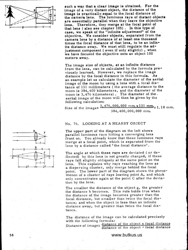
such a way that a clear image iE obtained. For the
                       image of a very digtant object, the dietance of the
                        image is pra-ctically.equal  to the, focal dietance of.
                                      The luminous rays of dietant objectr-t:i"'-                     the camera lene.                        are esEentially parallel when they leave the objective
                         lena. Therefore, they merge at the focal point of
                              that lenE ( aleo see chapter 105) .  In this type of                                                              ttinfinite adjuetmentrr of the                          case, we epeak of the
                           objective. We coneider objecte, separated from the
                        camera lens by a dietance of at leaet one thoueand
                          timee the focal distance of that lens, to be an infin'
                                ite dietance away. We muet still regulate the ad-
                          justment component ( even if only slightly) , when
                     we have focueed the objective onto an object 100
                         meters away.
                       The image size of objects, at an infinite distance
                                                              f rom the lens' can be calculated by the formula pre-
                             viously learned. However, we replace the image
                             distance by the focal distance in this formula. Ae
                        an example let us calculate the diameter of the aerial
                       image of the moon by using a lens with a focal dis-
                           tance of 131 millimeters ( the average distance to the
                     moon is 384r 400 kilometers, and the diameter of the
                       moon is 3,476 kilometers) .  Tbe diameter of the.
                             aerial irnage of the moon will then be given by the
                             following calculation:
                                                              3 476 000 000 rn   x 131                          Size of the image.                                = l. 18 rnm.                                                  384,400,000,000  rnrn

                        No. 76. LOOKING AT A NEARBY OBJECT
                       The upper part of the diagram on the left shows
                               parallel lurninous rays hitting a converging lens
                               front on. You already know that these lurninous rays
                      merge at a focal point, which is separated from the
                            lens by a distance called  I the focal distancer.
                       The angle at which these rays are deviated  ( or de-
                               flected) by this lens is not greatly changed,  if these
                           rays fall  slightly obliquely at the same point on the
                              lens.  This explains why rays reaching the lens as
                        a dispersing cluster,  only rnerge behind the focal
                               point.  The lower part of the diagram shows the pheno-
                      menon of a cluster of rays leaving point A, and which
                            only concentrates again at the point C after the devia-
                               tion by the lens.
                       The srnaller the distance of the object g, the greater
                             the distance b becornes. This rule holds true when
                             the distance of the irnage becomes greater than the
                              focal distance, but srnaUer than twice the focal dis-
                            tance; and when the object is less than an infinite
                             distance away, but greater than twice the focal dis-
                                tanc e.
                      The distance of the irnage can be calculated precisely
                             with the following formula:
                            Distance of irnage:- 4istancedGtatr-ce o{of lhethe oFiec!object x- {oca}focal 4islgncedistance
                                         www.butkus.us


                                                                                                                                                                                                                                                                                                                                                                                                    .!
View original page 1Page 2 · Read text
According to this formula, for an object that iE at a
                                         dietance of.2,75L meters ( or Z, T5I mm. ) , the distance                                              of the image is 13?.55 mm. if the focal dietance of tho                                            objective lene ie 131 mm.
                                  You now understand  (if a clear image of cloee objecte
                                                is deeired) , why the objective musisufficiently p"o-                                               trude.

   I
                                     No. 7?. THE OBJECTM  AS A TELEMETER
                                                                     If you direct the.objective at an object (and adjust the
                                              resulting aerial image with precision)  ,  it is possible
                                                 for you to calculate the distance from the obiective
                                                              t_9 the object (therefore,  the d.istance of the object)  .
                                         This is possible as long as you know the objectiver's
                                             focal distance, as well as the digtance between the
                                            objective and the aerial irnage ( therefore,  the dis-
                                                 tan-ce of the image which we have just adjusted)  .  The                                            following formula is to be used:
                                       Distance of object - Distance of imase x focal distance
                                                          Distance of irnage - focal distance.
                                                                    It is preferable to place a graduated scale in meters
                                      on the objective right away.
                                        This is why you have been provided with a printed
                                         scale e on the cut-out sheet.  Stick it onto ihe edee of                                           the universal adjusting component.
 I                                                                  It would be a good idea, first  of all,  to turn the ob-                                              jective in the universal adjusting component so that
                                         the scaler s lines are to the right and lo the left,  for I
                                           the initial and final positions.  Having cornpleted this,
                                       focus the lens on an object as far away as possible.
                                     Then, place the scale so that you can read the line                                    above the mark rinfinitel  .  The other nurnbers 10, 5
           www.butkus.us                 and 3 are meter readings, and you can draw in their                                       exact reference lines.
                                             In order to facilitate  the preparation of your tele-
                                           rneter attach  it to the back of a chair  ( use support #42,                                     as described at the end of chapter 103) .  ptace ttre
                                           chair a fair distance frorn a newspaper suspend.ed.
                                             frorn a door.  The distances 10, S a.ra 3 rneiers are
                                            useful, in this case, to adjust the distance frorn the
                                    newspaper to the front of the achromatic lens.  The
                                       iSage -can be adjusted rrrore precisely  if you look                                      through a magnifying glass ( see chapter g5) , holding                                          large obturator  I in front of the objective fens ( part'                                      #55 with a 12 rnm. opening)

I                                   No. 78. A LENS WITH VARIABLE FOCAL DISTANCEI
l                              No lensr maker has ever been able to construct one                                            of these.  Stil1, each hurnan being has two such lenses-                                     one in each eye.
                                To the left of the opposite diagram you see how parallel
                                     luminous r?ISr deviated by the lens of the eye, rneet

                                                                                                           59
View original page 2Page 4 · Read text
at a certain point behind the eYe.
                         To the right, you see an eye in which the lens is
                                thicker and its surface bulge rnore accentuated, than
                               the one on the left.  This is because its focal distance
                                      is so short that rays frorn point A rneet behind the eye
                                 at a precise point,   If the lens shown on the right re-
                          mained as flat as the one in the eye shown on the left,
                              then the rays could meet behind the eye only if they
                         were parallel  to one another.
                         The following diagram on the left shows you the ocular
                              lens L on a larger  scale, in its flat resting stage
                                            ( to the left)  , and in its tense or active state ( to the
                                    right)    .
                             Notice the rnuscles M, which , because of certain
                             nerves, can produce a tension on the edge of the lene.
                             This causes an alteration in the lens, shortening  its
                                focal distance.  Naturally,  these muscles are not
                              only placed above and below the lens( as shown in our
                              cross-section diagrarn)   They surround the entire
                             eye lens, forrning a rnuscular ring,
                             This adjustment of the ocular lens ( professionals call
                                                       it  accomrnodation to near objects)  tires the eye rnore
                              than the observation of distant objects, since the lensl
                               rnuscles are used to Droduce tension.
                          There is more to see in the diagrarn:  Notice that the
                              lenses are not on the outside surface of the eye, but
                                 rather,  behind and towards the rear.  There is,  first
                                 of all,  the outside layer  - the transParent cornea
                                            ( rnarked H) .  Behind the cornea is a transparent
                                   iiquid called the aqueous hurnor ( rnarked K on the
                               diagrarn) .  This liquid bathes the front surface of
                               the lens L, and its suspension systern.  The rear
                             surface of the lens rests on the ocular globe ( labelled
                         G) on a concave reinforcernent of the aqueous and
                               vitreous body, filling  the other parts of the eye.
                                 In front of lens L, there is the iris,  J.   It acts as
                         a diaphragm ( obturator)  with a variable opening.
                         The pupil  ( K)  is its opening, allowing the free entry
                                 of iight.
                         The iris works automatically:  the stronger the inci-
                              dent light,  the rnore  it closes.  The diarneter of the
                                pupil varies frorn 7 or 8 rnrn. ( when it is dark)  , to
                              1.5 or Z rnrn.(when the light is intense)   ..
                        You can observe the rnobility of the pupil openingl
                                     First,  place yourself in a dark corner  ( where there                                     i
                                      is only very dirn lighting)  , and look at your irnage
                                   in a rnirror.  Now, shine a bright light on your face.
                             Notice                                        that your pupils contract when exposed to                 {                                 bright light.
                         You can also test the rraccornrnodationrr of the ocular
                                lens.  HoId a pencil about 25 crn in front of your right                             eye, and close your left eye.  Place yourself in front          f
                                            www.butkus.us
60
View original page 4Page 5 · Read text
of a painting, while holding a pencil before your eyes.
               Now, focus on the pencil tip  - you should see it
                     clearly.  Then, glance at a point on the painting ( right
                  beside the pencil tip)  , without rnoving.   If you allow
                 your eye to shift to the point on the painting, Iou                        will notice that the pencil tip now appears very hazy.
                  This is caused by your eye adjusting its focus to the
                  rnore distant painting.

                No. 79. AT NIGHT ALL CATS ARE GREY
                The opposite diagrarn shows you a cross-section  of
               a right eye. You see the well defined line indicating
                    that the back of the eye is covered by a filrn.   This
                       is the retina  ( N) , and has a thicknes s of. l/Z  rnrn.
                The retina surface is cornposed of nurnerous ultra
                     light-sensitive  cells.
                The are.a of the retina,  directly  before the pupil is
                  indented.  This indentation, called the rcavity of the
                      retinal  is the center of vision.  At point B, on the
                  other hand, light-sensitive  vision .Llls are entirely
                  absent, for  it is from here that the optical nerve
                  Ieaves for the brain.  Looking at the diagrarn, you
                    rnust be asking youself what this cross and this large
                      circle,  both frarned by a rectangle, can pbssibly mean!
                You will see its use imrnediately.  Close your left
                 eye, and look at the center of the cross with your
                     right eye ( from above and at a distance of approxi-
                 mately 40 cm.) .   If you slowly bring your dyb closer
                    to the cross - while  still focusing on it  - the black
                  spot suddenly disappears, but the frarne rernains
                     visible.  How is this possible?o                             If you refer to the preceding diagrarn, everything
                      wiII becorne clear.  When a cluster of rays hit your
                     right eye front on, these rays can rrrerge precisely
                    at that point of the eye where the vision cells are
                   cornpletely absent.  This point is labelled B in the
                  cross-section diagram of the eye.  Consequently,
            B represents the blind spot in the eye.  Fractions
                    of irnages touching this spot rernain invisible and
                             itr s arnazing that the irnage is not jolted or inter-
                 rupted at this spot.  Only the irnage part that happens
                    to be located over the blind spot smoothly disappears,
                             If  ( instead of a black spot on a white background)  ,
                  there were a white spot on a black background, the
                 white spot would then disappear and black frarnework
                would remain visible,+
                   Naturally,  the left eye also has a blind spot.  Test
                 your left eye by placing this rnanual upside down in
                    front of you.
              On a starry night,  it is possible to perform a similar
                 experiment.   If you stare at a certain star that glows
                 very weakly, you may suddenly see it disappear.
               However, this time, the disappearance takes place
                    at the precise moment that you were gazing very
                    fixedly at the star.  As soon as you glance sideways,
                                                                               5l
View original page 5Page 6 · Read text
the star reaPPears - exactly as though there were
                             also a blind spot at the center of your line of vision,
                                  er,  at the indentation area of the retina.  This is
                                aciually the case!  But isnr t there a contradiction in
                             saying that there is a blind spot in the center of your
                                  line of vision?
                          No, because there are two types of vision cells in-the
                         eye - the cone-shaped ones ( cone cells)  and the
                             stick-shaped ones ( rod cells)   .
                          Cones are less sensitive to light rays ernitted by weak
                                 stars.  They donlt even register these rays!   Further-
                                   rrrore, the cones are particularly  dense in the retina
                               indentation.  In fact, there are 41 000 of them in that
                              area, each with a thickness of only .00I5 mm. !  There-
                                  fore,  in this area, there is no space for rod cells
                                                 ( which are ultra-sensitive  to light)  .  Hence, because
                                of weak light rays, a second blind spot aPpears in the
                                retina indentation.
                      Do you wish to know why the retina indentation is the
                             cenfe" of our vision?  This is simple.  The light-
                               sensitive rod cells are far thicker than the cone cells.
                                                If a section of the retina were cornposed exclusively
                                of rod cells, images would be very crude and have no
                                 de tail.
                                                If we wish to view objects with precision  ( as in the
                                retina indentation) , then the thin cone cells are rrrore
                                  practical,  for they ate far more nurrrerous in that
                               indentation.  Lurninous raysr corning frorn two dis-
                                     tinct points situated very close to one another, can
                           reach two separate cone cells.  The rod cells are so
                                large,  that the rays would reach the sarne cell.  Con-
                              sequently, they would be seen only as one light source.
                        The cone cells donr t work in a shady arear since we
                           can only perceive images registered by the thick rod
                                    cells.
                         The cones ( which need a strong intensity  of light in
                             order to work efficiently)  have another advantage.
                          They make visual perception of colors possible. How
                     we see colors is one of the rnost fascinating questions
                            explored by naturalists  in the last 150 years.  Thanks
                                 to the research work of Professor Dr. George Wald
                                                 ( who received the Nobel prize in medicine with two
                              other scientists in 196?) , we now know the answer.
                          There are three different tyPes of cone cells.  One is
                                sensitive to blue raysr one to green rays and another
                                 to red rays.  Therefore, the color image is forrned in
                            our eye approximately the same way as in a TV.
                                            ( You are farniliar  with the TV rnechanism from
                              chapter 40. )  You can now understand what color-
                               blindness  is. A color-blind Person has only two types
                                 of cone cells  - or one or two of the cone cell types
                       may not work properly.    ( You know what this rneans
                           from chapter 39.)
                                            www.butkus.us
6Z
View original page 6Page 7 · Read text
The rod cells, however, react principally  to bluish
                                        light.  Since they do not reproduce shades of colors,
                      we see everything with a bluish-gray  tint in dirn
                                        light.  The popular expression,  rrat night all cats
                             are greyrr, here is thus scientifically  explained.
                                                   If you consider that the retina has rnore than one
                             hundred million rod cells and more than six million
                            cone cells, you will understand that the TV carnera
                              (which we consider to be a technological triumph)  ,
                                       is actually a very primitive  instrument in comparison
                                with the human eye.
                           However,  it is  still  true that fro^m the visual angle of
                                the eye ( which is I40o) , only ?o are useful for ihe
                                 clear observation and deciphering of. a given object.
                              This is because the density of small cones dwindles
                                  rapidly from the center of the retina towards the
                                   exterior,  so that the very edge of the retina consists
                               only of rod cells.

                           No. 80. EYESIGHT AND GLASSES
                          Have you already checked to see if the lenses of a
                                  pair of glasses are converging or divergent?  If so,
                                   yourll  have noticed that glasses worn only for reading
                             are usually made with converging lenses, and have a
                              very small bulge.  Usually, elderly people use these
       Norrnal vision          type of glasses, With age, the strength of the eye
                                rnuscles dwindle, and the lensr contraction also de--@               creases.  The result is that only distant objects are                                  clearly visible.  We say then that the eye is pres-
                             byopic - or that the person is far-sighted.
       PresbYoPic@@      For presbyopic eyes, the eye lensr focal length is
                              longer than its distance from the retina.  Naturally,
                               there are also people born with an ocular globe too
                       www.butlkus.ussmall for the focal distance of the lens.  These poople
                                therefore suffer from a  I congenital presbyoilic
         Myopic                  afflictionr   .@1@
                             Far-sightedness can be corrected by glasses with
                              converging lenses.  Such glasses deviate the incident
                            luminous rays so that ae soon as rays reach the
                               glasses they begin to merge.  This type of lens, there-
                                   fore,  shortens the focal distance of the eye lens.
                                Instead of  t the focal distance of the lener , opticians                            use a number called a rrdiopterrr. Do you want to know
                                 the.focal distance of the lens of a pair of glasaes? To
                           do this,  divide the number, one, by the diopters given,
                           and you will thus obtain the focal distance in meters.
                              Therefore, __l_         .  Focal dietance in meters.                                          Diopter
                            For example, the lens of a pair of glassee of two
                                 diopters, have a focal distance of l/Z m" or 500 mm.
                            Of couree, there are also glassea with divergent lene.
                           They are used for rnybpic ( or near-sighted)  people.
                                  In this case, the focal distance of the eye length is so

                                                                                         63
View original page 7Page 8 · Read text
short, that the incident rays hitting the eye merge
                              before they reach the retina  ( as you can sqe in the
                            diagram) .  Either the ocular globe is too large,  or the
                              lens is too curved.                Visual acuitv
             when read    Divergent lenses used in a pair of glasses, affect the
               from a          light rays so that they begin to disperse before hitting
                distance of    the eye. The result is a greater distance between the
     -                         eye lens and the image situated behind the lens.  The
                               divergent lens lengthens the focal distance of the eye       --,2m.        -.                         lens.  Whether someone needs.to wear glasses or not,
                            depends on his acuity ( or, sharpness) of vision.  L'
                    We check visual acuity with sheets of paper on which
                             broken lines of varying length are drawn. We say
                                 that a person has a normal visual acuity of 1.0 if
                          he can still perceive a .75 rnrn. space between Z broken
                                                                        see                                                                    rn.                                                                    Ifhe                                                                     a dis-                                                  ofZ                                                            can only                                     a                                              distance                                         frorn      -JI                     or3            lines,     I                                                   Z                                                                               eyesight                                              between                                                                              his                                                        broken                                                rnrn.                                                                             lines,                                      1.5                              tance of             -                                       is only half as good and consequently, he has a visual
                                acuity of .5.     -Z
                            With the diagram on the left,  you will be able to test
                             your visual acuity.  You must check each eye separatel.y
                            so be sure to close your other eye.  W-hen you can per-
                              ceive the position of the spaces in the circles,  Iook to o                 the right of the page for your visual acuity score.  Of
                              course, you rnust look at the page from a distance of
                          Z rn.  Your visual acuity corresponds to the line in whichoo                           you can see the separations in the srnall circles  perfectly. oco                                   0.50        The hurnan eye is not, however, the most perfect eye. occ        0.70         Birds have a far greater visual acuity.  Therefore,  a oooo               falcon can very distinctly notice a hole in the ground
                                               t.0          with a 2.5 crn. diarneter frorn a height of 500 rneters.  ccoo                     A hurnan being with normal eyesight, cannot even see   ooooo                                                      I,L         an 8 cm. hole from this height. He can only see a hole
    oocco                     2.0            distinctly   if  it has a 15 crn. diameter.

                           No. 81. USING A MAGNIFYING GLASS
                        To see a certain object clearer, we place  it under a mag-
                                  nifying glass.  So, take your converging lens #4 and hold
                                                        it 1 or 2 crn, above this page. Part of the print  will
                            appear larger than it actually is:  the converging lens
                              acts as a magnifying g1ass.
                                                  If you bring your eye very close to the rnagnifying glass,
                              the image remains clear as long as you vary the dis-
                              tance between the magnifying glass and the printed text.
                            Presbyopic people, not wanting to wear glasses, use a
                             magniiying glass for reading, not because of the larger
                                      print,  but bicause the magnifying glaee provides better
                                          ilarity    if  it is used in a normal reading position.. Other-
                               wise, they could not read unless they held tJre printed
                            page at arml s length.


                                           www.butkus.us
64
View original page 8Page 9 · Read text
r-
                                                               If you bring the page too close to the magnifying glass,
                                   you only see a very h.azy picture.
                                                               If you need a gmall magnifying glass, but you donr t
                                  have a converging lens, simply place a drop of water
                                    on a clean piece of glass or on the flat surface of a
I                                     transparent ruler.    If the drop of water does not
                                                 trickle,  you will have a small converging lens with
                                 a focal distance of approxirnately 15 rnrn.   It can be
                                    used as a rnagnifying glass if you bring your eye
                                       cloee to it.  Even though  it magnifies print more
                                      than a norrnal reading magnifying glass,  it is not
                                      appropriate for reading because of its small diameter.

                                  No. 82. THE ENLARGEMENT CAPACITY OF A
                                    MAGNIFYING GLASS
                                      'When you see an object enlarged 8 tirnes by a rnagni-
                                         fying glass, this means that you see tJre object 8 tirres
                                         larger than it actually is.  By  I actual sizer , we rrrean
                                        the dimensions which an object usually seems to have
                                          at observation distance of 250 rnm.
                                                                   Itl s easy to perform an experirnent determining the
                                    degree of enlargement produced by converging lens
                                     #+. HoId screw #72 with a pair of tweezers and look
                                          at it through the lens.  While looking with both eyes
                                   open, focus one eye on the part of the wall in front
                                          of you that coincides lengthwise with the enlarged
                                  image of the screw.
                                  Then, hold a ruler at a distance of 250 mm. in front
                                          of your eyes without rnoving.  Check the length in-
                                        dicated on the ruler  to find the length you had pre-
                                        viously noted on the wall in front of you.
                                           Letl s say you saw an enlarged irnage of the screw
                                      6.7 crn. in length, and the screw itself has a length of
                                   8 mm.  You then saw  it enlarged 8.3 times, and the
                                      converging lens #4 therefore, has an enlargernent
                                      capacity of 8.3.  However, you can also easily cal-
                                       culate the enlargernent of the magnifying glass with
                                        the following formula:
                                       Enlargernent of magnifying glass :___ 359 mm,
                                                                 Focal distance in rnm.
                              To the left of the diagram, you see how screw AB is
                                    reproduced as CD on the eye retina, when it is at a
                                        point 250 mm. from the eye. The center drawing
                                 shows that the larger irnage FE would be situated
                                             far behind the retina,   if the distance between the eye
                                 and the screw was diminished to length b. On the retina
                                                   itself , only a vety hazy picture of the screw would
                                    appear.  The right-hand side of the diagram shows
                                  you that by placing a magnifying glass between the
                                 screw and the eye, the irnage CD is reproduced with
                                               clarity on the retina, you can also see at what size
                          GH is, seen 250 mrn. from the eye.
                              From what has preceded, you will understand that
                                image GH is a virtual image, gince it is seen in the

                                                                                                 65
View original page 9Page 10 · Read text
direction of the extensio4 of the deviated rays ( see
                             chapter 38 and the end of chapter 73)  .
                                                 If you hold the scale from rnicrorneter #l3a under
                              converging lens #4 instead of screw AB in the right-
                          hand side of the diagram and place the millimeter
                               scale from the front of the book on a table 250 mm.
                            below your eyer )rou will see both scales super-
                           imposed.  The rnicrometer divisions consist of 60
                                sub-divisions.  Each group of 10 sub-divisions
                              equals 1 mm.;  therefore,  the rnicrometer divisions
                          measure 6 mrn.  'W'ith an 8. 3 enlargement this divi-
                              sion ( seen enlarged through converging lens #4)  ,
                            covers 50 mrn. of the millirneter  scale.  This is
                           seen gimultaneously with your free eye, at a dis-
                              tance of 250 mm.

                          No. 83. DISTAI\CE OF THE EYE FROM THE
                              MAGNTFYING GLASS
         250nn                  Observe the screw through the magnifying glass held
                             close to your eye ( Ieft side of diagram)  , and then
                               bring your eye slowly away frorn the magnifying glass
                                         ( right side of diagram)   The enlarged part GH be-
                                   corrres smaller and smaller.  The points A and B
                                            ( from which the lurninous rays hitting the eye are
                              emitted)  , come closer and closer together as the
                           eye is brought further away from the rnagnifying
                                glass.  When the eye is far enough frorn the magni-
                                 fying glass, the rays are nearly parallel between
                              the rnagnifying glass and the eye.  In this case,
                               points A and B rneet at the focal point of the magni-
                                 fying glaes ( if the magnifying glass is rnaintained
                            above the observed area at a distance equal to its
                                 focal distance)  .
                         The largest visual field is obtained when your eye
      -A   A                is as close as possible to the rnagnifying glass.  You
       ..1-\     .:IN               will see that the image is too distinct   if you look into                                the planar surface of the lens rather than the bulging
                                one.

                           No. 84. SMALL LENSES WHICH ARE STRONGER THAN
                            LARGER ONES
                        Now, use srnall converging lens #6 as a rnagnifying
                              glass rather than converging lens #4. You can see
                                 that it enlarges rrrore strongly.  This is not sur-
                                  prising,  since  it has a smaller focal distance and
                               therefore gives a greater enlargement.   ( It enlarges
                          by 16. 7 tirnes - see chapter 82.  )                                                                           {
                         The srnaller the focal distance of a lens, the greater is
                               the bulging of its gurface.  The sphere ( of which the
                              lens is a part)  therefore has a smaller diarneter when
                               the focal distance of the lens is srnaller.  That is why
                               the diarneter of a lens which greatly enlarges, cannot
                          be as long as that of a lens which enlarges only slightly
                            and which has a nearly flat surface.
                                         www.butkus.us
66                                            I
View original page 10Page 11 · Read text
For easier handling in tests corning up, srnall converging
                                         lens #6 will be placed in support #17.  If lens #5 is  still  in
                                            part # 17, rernove it.  On the KOSMOS side of support #I?,
                                       are six ribs at the center holers edge: three are tall and
                                                  thin; three are thicker but shorter.  Lens #6r s edge should
                                             rest on these latter  ribs.  Part #I7 is injection-moulded
                                              frorn plastic and srnall bits rnay rernain on these ribs when     @-'s                                           the rnould is lifted.  Scrape this off with a pen-knife.   IfrI                                         lens #6 is not in position,  it distorts the picture.  Place          *gr;fl                  Iens #6t s flat side on wheel #Z9r s hub.  Bring the hubhole                         -'            to exactly the lensr center.  Before placing part #l? over
                                           the wheel, check that the lens is in the center under the
                                       upside-down support - otherwise the lens could be lopsided
                                    and the support darnaged.

                                    No. 85. THE IMAGE ON THE SMALL MAT DISK SEEN
                                    THROUGH A MAGNIFYING GLASS
                                       Using the magnifying glass ( forrned. by lens support  f 17
                                    and srnall converging lens #6) , you can observe the image
                                    on the rnat side of the disk ( cut frorn rnat screen #371 in
                                           the telerneter frorn chapter 77. When you hold the eye lens
                                        support by its open side (on the extrernity of the telemeter
                                         tube) , you have the correct distance with which to pre-
                                             cisely observe the image.  Naturally,  the exterior side of
                                         the eye lens support is turned towards the eye.
                                  You now see the irnage on the mat disk enlarged by 16.7
                                           times.    If you point the telemeter towards the rnoon, you
                                         then see it with a.diameter of approximately 19.7 rnm.
                                                         ( see chapter ?5)  .
                                                                    If, on the other hand, you hold a ruler 250 mrn. in front
                                             of your eye, and deterrnine the diarneter of the rnoon
                                 when measured in this way, you discover that it is 2.26
                                             rrrm.  If you cornpare the diarneter of the moon as seen
                                                 in the rnat disk, with the diarneter seen with the naked eye,
                                        you will  realize that you see it 8.? times larger through
                                           the telemeter.
                                To calculate this you must only check how rnany tirnes
                                       2.25 is contained in I9. ?.  Therefore,  divide Ip.7 by
                                            z.26.

                                No. 86. KEPLERT S TELESCOPE SIMPLIFIED
                                As you rernernber, we used the rnat surface of the disk
                                              in order to see the aerial irnages projected by the ob-
                                            jective lens ( see chapter 74) . We should be able to
                                        observe the aerial image just as well by using the rnag-
                                              nifying glass directly. To try this, remove the rnat
                                           disk with its moveable support from the sliding tube,
                                           but leave the telerneter as it is. So that the support of
                                         the eye lens is rnaintained at the correct distance from

                                                introduce the eye lens support ( with its srn311      .47                  theFirst,aerial image, use field lens support #18.                                         converging lens) into lens support #18 as indicated in      -t,                                         the diagrarn. You will notice a reference line between

                                                                                                    67
View original page 11Page 12 · Read text
the eye lens support and support #18.  Introduce lens
                               support #18 into the sliding tube of the telemeter until
                           you have reached this reference line.  Make sure that
                                the eye lens support still  protrudes.
                             At this point, you are ready to observe the aerial image
                              through the small converging lens #6 which is now acting
                          as a magnifying glass, and which we shall now call the
                           eye lens.  The irnage seen through the eye lens appears
                              8.7 tirnes larger than in reality.  The instrurnent which
                           has been built from the objective lens and the eye lens
                                      is therefore a magnifying glass which enlarges 8.7 times.
                             This telescope is different from Keplerr s telescope since
                                         its eye lens is a converging lens, and it produces rever-
                           sed irnages.  Instrurnents of this nature are called
                                   rrKeplerl s telescopesrr, because the discovery of a tele-
                           scope in which the objective lens and the eye lens were
                              converging lenses, is attributed to the famous Gerrnan
                                  naturalist Johannes Kepler.
                             Kepler is especially famous as an astronorner, and ob-
                             served the heavens with his telescopes. He did not
                             consider the problem of the reversed irnages irnportant
                             because when observing celestial bodies,  it does not
                             matter  if the images are reversed.  Moreover, he
                           wanted to avoid any loss of lurninosity and tJre danger of
                                errors  in representation that rrstraightened outrr reversed
                                    irnage s .
                         The Kepler telescopea are  still used today.  Naturally,
                             Kepler had corrective instruments added to sorne of his
                              telescopes.  These telescopes are called rterrestrial
                                telescopesl  , for they are different than  I astronornical
            www.butkus.us         telescopesl.
                              Unlike your simplified Keplerr s telescope  ( the cross
                              section of which is represented by the diagram)  , Keplerr s
                              telescopes did not have an achrornatic lens, but had only
                         a simple converging lens at the objective.
                        When you focus the telescope on a certain object, you
                                        will  certainly notice how the adjustment can be modified
                                within certain limits   ( without thg clarity  of the irnage
                              being diminished)  . How can this be done ?
                                                 It is actually very easy! When the magnifying glass,
                              through which you observe the aerial irrnge ( in this
                           example the srnall converging lens #6) , is separated
                                 frorn this aerial image by a distance equal to its focal
                               distance, the rays corning frorn a point in the aerial
                               irnage are parallel to one another.  This image is then
                           seen clearly  ( to the eye)  if we adjust the lens to infin-
                                           ity.  The nearer the magnifying glass is to the aerial
                           image, the rnore the luminous rays (while coming frorn
                              the aerial image) diverge.  Despite this divergence,
                               they always rnerge on sorne part of the retina when the
                           eye adjusts to vieyv a close object.
                              Consequently, the eye compensates for certain differ-
                           ences in telescope adjustment.  The eye muscles are
                                             www.butkus.us68
View original page 12Page 13 · Read text
very much in use when the telescope is not properly
             adjusted.
             In order to observe for a long time without tiring  the
           eyes, when viewing a very clear image, the telescope
          must be adjusted so that the distance between the ob-
             jective lens and the eye lens is as great as possible.
           This is valid for  all telescopes, theatre binoculars,
           and ordinary binoculars.  You will be able to adjust your
            telescope more easily  if you turn the objective tighter
           and then try to obtain a clear irnage by unscrewing  it.
             In this way your eyes will be relaxed after the initial
            blurred image.
           People who wea! glasses can use binocularg without
           wearing their own glasses since they can adjust the
            binoculars.

          No. 87. THE PRECISE ADJUSTMENT OF KEPLERT S
               TELESCOPE
         As you have learned in chapter 68, we cannot obtain
          a clear image with the telescopes unless the parallel
            lurninous rays, reaching the objective lens, are still
             parallel when they leave the eye lens.  These rays are
            only inclined relative to one another between the camera
            lens and the eye lens.
             In Keplerl s telescope, this condition is always fulfilled
         when the rear focus of the objective lens LI coincides
            with the front focus of the eye lens L2.  On the diagrarn,
              this common focus point is shown as Fg. By adjusting
            Keplerl s telescope to infinity, we obtain the necessary
            distance to do this.  Add the focal distance of eye lens
         FZ to the focal distance of the carrrera lens Fl between
           the objective lens and the eye lens.  For your sirnplified
            Keplerl s telescope, the totat distance is therefore,
                l3l mm.  t 15 mm.   146 rnrn. You already know (from
           chapter 76) that the =length of the telescope increases if
         we focus  it on nearby objects, due to the fact that the
            distance between the objective Iens and the image pro-
            jected by it, becomes greater.

          No. 88. HOW THE ENLARGEMENT IS PRODUCED IN
               KEPLERIS TELESCOPE
         You already know ( frorn chapter 69, which dealt with
            the adjustrnent of the telescope to infinity)  that parallel
            lurninous rays, leaving the eye piece, parallel to one
            another, have nothing to do with the enlargernent of the
            telescope. The enlargement depends on the cluster of
             parallel rays hitting the objective at a small angle and
            Ieaving the eye lens at an even more oblique angle.
          However,  it does not deterrnine the enlarging properties
             of the telescope  if the cluster of parallel lurninous rays,
             exiting frorn the eye lens, has a srnaller diarneter than
                  of the incident ( or entering)  cluster.'iiir""      that
         On the oppoeite diagram we have drawn only one tay of

                                                                    69


                                               a.,:
View original page 13Page 14 · Read text
the cluster,  becauae we are dealing with the angle at
                          which the lurninous rays reach the objective lens, and
                             the angle at which they leave the eye lens.
                            Notice how the lurninous incident ray ( or entering ray)
                          forms a small angle with the axis of the telescope at Fl.
                              Since we have chosen a ray which crosses the front focus
                              FI  of lens L1,  it is clear that, the ray travels parallel
                                to the axis of the telescope between lens Ll  and L2.
                         However, this ray is then refracted  ( or broken) by
                          eye lens L2 so that it crosses the rear focus FZ.   If the
                               focal distance of. LZ is shorter than that of Ll,  then the
                                optical angle at FZ is greater than the one at Fl.    If
                                 tiee A catt be seen through the telescope with a larger
                                optical angle ( C) than with the naked eye,-it is.because
                                      tie telescope enlarges objects on which it has been focused.
                         The enlargement occurs when the focal distance of lens
                                  Ll  is g".Jte"  than that of lens L2.  So, we can say ( as
                      we did for the GaLilean telescope)  : Enlargernent of the
                            telescope = Focal distance !f  the objgctivq lene                                          Focal distance of the eYe lens.
                                             'ffith this forrnula you can check  if the enlargement  ( which                         had been previousiy calculated)  for your Kepler tele-
                           scope is the sarne.  Enlargernerrt of the telescoPe':
                           131 rnm. 3  8. ?3 times, or ( in round numbers) 8.7-  '
                            15 rnm.
                       When comparing the trajectory  of the rays in Kepler.r s
                              telescope *itn   tft" diagrarn of the trajectory  of rays in
                             the Galilean telescope, your11 understand why the images
                                   in the Kepler telescope are upside down. The irnage seen
                            through the Kepler telescope is of course, a virtual  one.

                          No. 89. IMPROVING THE EYE LENS
                         The Kep1er telescope described in chapter 86 obviously
                              doesnr f produce very clear images.  This is why wel ll
                              irnprove this telescope step by step, until  ( by chapter
                              94) , we finally  obtain absolutely perfect images.
                                 Letl s start with the eye lens.  Undoubtedly, you have
                               noticed that the field of vision is foggy if you even glance
                               obliquely into the eye lens.  This problem really bother-
                           ea the firnous Dutch physicist Christian Huygens, who
                          woiked at improving the Kepler telescope.
                         Huygens perfected the eye glass of Keplerl s telescope
                              Uyloining  it to a second lens.  This lens is called the
                                             ttii;Id  lens", and its focal distance, and distance from
                             the eye lens, are synchronized. You can improve the
                             eye lLns of your own Kepler telescoPe by placing this
                                     field lens into it.@o                                   First  of all, remove the eye lens.  At this point,  it is
                              cornposed of an ernpty field lens support in which we g_,.ffi                            havJintroduced the eye lens support containing the eye
                              lens from the Kep1er telescope.  Rernove the field lens
                              support, the eye lens support, and its eye lens, and@-,M                             put thern aside.
                                            www.butkus.us
70
View original page 14Page 15 · Read text
'To incorporate the field lens into the field lens support,
                                         it is preferable to use picture-counting dial suppori
                     #30.  Place converging lens #4, with its bulged surface,
                     on the upper edge of the round hole of part #30 ( as shown
ffi-,r-,               in the diagram) .  Then, hold field lens support #18 r{Fr  ffi          andexactlylookoverinto thesethe obturation(its  largestholeend( whichtowardsis onthethebottom)field      ,                      Iens support) , to check that the lens is situated exactly
                         at the center of the support.   If this is so, place the fieldkJ-''-ElL,                   lens support exactly on the planar surface of the lens and
                     press firmly  until the lens is well fixed onto the 3 grooves
                         of this support.
                   To ensure that the field lens is not lopsided, the planar
                      surface of this lens must rest all around on the slightly
                     grooved interior  surface of the field lens support.
                          Finally,  replace eye lens support #1? with eye lens #6
                      onto the field lens support.  'We have thus improved
                      Keplerr s telescope according to Huygensl ideas.

                   No. 90. MODIFYING KEPLERT S TELESCOPE
                  Now, place Huygenst eye piece into the sliding tube of
                      Keplerr s telescope until the separation between the field
                      lens support and the eye lens support is ( as before)  ,
                      barely visible.  The adjustrnent cornpleted, you will
                       notice that the iheage appears very stable.  Moreover,  if
                     you look into the eye lens obliquely, you will see that
                       the field of vision has been widened.  This, however,
                            is produced at the cost of sorne properties of enlarge-                     ment.
                   The image is now much clearer than it waEwithdut the
                           field lens.  Unlike the single lens, this new eye piece
                   even corrects colors  ( as you will see later on) , al-                     though it is not achromatic ( and is cornposed of-two
                     lenses made of the same material)    .

                   No. 91. THE FIELD LENS IMPROVES THE IMAGE
                                   If you would like to know what opinion Christian Huygens
                   had of the eye piece he had just invented., look at thele
                    two diagrarns.  The upper one shows a very simple
                        Ke-pler telescope with 3 parallel lurninous rays tatting
                    sideways on its objective lens.  Having been deviateiUy
                       objective lens Ll,  these rays cross ejch other at one
                       point in the interrnediary irnage Zw ( tihe aerial image
                    between the 2 lenses of the telescope)  .  The center-of
                         this interrnediary image is focal point fg.   AJter having
                    crossed one another at this point, the rays disperse once
                        again.
                    Using eye lens LZ as a magnifying glass,  it is possible
                       to observe this interrnediary image.  However, we can
                     only see rays which have been deviated from LZ towards   r
                     the eye ( for example ray 3) .  Rays Z and I pass beside                 LZ and disappear.

                                                                                        ?l


                                  :  i..
View original page 15Page 16 · Read text
If we place field leng L3 in front  of' LZ in the trajectory
                   L: Lz         Ja        of the rays ( see the diagram) , then the rays are deviated
                                                                                                                                                    'l                            sooner than before slightly towards the center, and before
                                     F2          the intermediary  itnage Zw.  Rays 2 and I also reach the
                  7w Ft          eye by way of L2.  With a field lens, more rnarginal rays
                            are deviated towards the eye, so you can now look rnore
                               obliquely than before at the eye lens-
                           Moreover,  tJre image is clear,  since therrspherical
                                  defectrr ( see chapter 95) is largely compensated  for by
                               the {act that the rays cross between the two lenges.
                         The marginal rays, that cross field lens L3, pass through
                       LZ as mediatt rays.  The rays that cross L3 as median
                               rays, pass through LZ as marginal rays.
                                 Finalty,  the chrornatic aberration caused by field lens L3
                                     is compensated for by L2, so that the ocular globe is
                                  chrornitically  corrected.  This was not the case when we
                          had lens LZ alone!  This chromatic correction  ( color
                                correction)   is always produced when two converging
                             Ienses rnade from ideniical substances, are placed beside
                          each other at a deterrnined distance from one another'
                       From this we get the formula:
                            Distance between lenses  I                                                                             .
                                         Focal distance  ( f) gf  lst lens * f of ZESI lens
                                                                                 z
                                In the case of Huygensl eyepiece, this chromatic
                               correction can be explained as follows:
                         Red rays are more weakly deviated than blue tays by
                               the field lens ( which acts as the first  lens of the eyepiece)
                         The red and blue rays ( into which the incident white ray
                          has been decornposed)  , consequently disperse between
                               the field lens and the eye lens of the eye piece.  The
                            eye lens of the eye piece which acts as a second lens
                             behind the field lens is therefore,  hit rnore frequently
                           by the red rays than by the blue ones. However, each
                             lens deviates more rays touching  it on the edge than
                             those touching  it as medians.  Thus, in the second lens,
                             the red rays are more strongly deviated than the blue
                            ones, and they leave the second lens parallel  to the blue
                               ones.
                             This is why the chromatic correction  is first  effected in
                               the eye. The lurninous rays entering the eye parallel
                                 to one another, are concentrated by the lens of the eye
                                 at a focal point situated precisely on the retina.  Thus'
                            red rays and blue rays rneet on the retina at a single
                               point of a given image, whereupon they again-merge as
                             white light.
                          There is only one disadvantage with Huygensr eye piece.
                          Enlargement by the sirnple magnifying glass cannot be
                                attained, since the field lens deviates the rays a little
                           towards the center, and in front of the intermediary
                           image, so that the intermediary image contracts'  When
                       we jdd the field lens, the enlargement which we had pre-
                               viously attained with the magnifying glass, becornes lZ. 5
                                            www.butkus.us
7Z
View original page 16Page 17 · Read text
times rather than 16.7 times ( approximately 3/4 of its
 previous value) .  The Kepler telescope, when used
with the Huygensr eye piece, enlarges objects only by
approximately 6. 5 times.

No. 92. THE AERIAL IMAGE BEHIND THE TELESCOPE
 It seems peculiar,  but the eye piece can function as an
 objective.  W'e are not referring here to the case in
which you look into the wrong side of your telescope and
 thus see shrunken images.  'W'e are thinking now of an
 aerial irnage occurrence ( of the opening of the objective)  ,
which is produced outside the telescope by the eye piece.
 This image is seen from the interior,  and appears to
you in the forrn of a clear floating disk, a few 4m.  in
front of the eye lens.  You may calculate the diarneter
 of this small disk, which we call therrexit pupilrr ( or
ocular circle)  with the following formula:
Diameter of the e*it pupil=liemeter  of th.-ca*e
                        Enlargement of the telescope.
The diameter of the exit pupil is equal to the diarneter of
the cluster of rays which have passed through the eye.
The dimension of the exit pupil thus indicates the lurnin-
osity of the irnage seen. For observations during the
day or observations of a clear object ( for exarnple, the
lunar surface) , the exit pupil must have a diarneter of
3/4 rnrn. r- otherwise the irnage is too dark.  For
Huntersr binoculars  ( used after nightfall)  , or astrono-
rnersl telescopes, the exit pupil must obviously be rnuch
larger.  However,  it is useless to make it larger than
the diarneter of the eye pupil when  it is cornpletely open
in the dark ( approximateLy 7 rnrn. )  .

No. 93. PLACING THE DIAPHRAGMS
Notice that the exit pupil of your Kepler telescope is
surrounded by a clear border.  Looking at it more
closely, you realize that this is caused by light reflected
into the telescope by the interior  walls of the objectiver s
half shells. We rnust rernove this secondary light for  it
causes the dark points of the image to turn pale.  The
good quality of the telescope image is darnaged by light
emitted.frorn a point laterally  outside itre field of vision.
This secondary oblique light can easily be elirninated
when the diarneter of the tube is greater than that of
the cluster of luminous rays,  contributing to the forma-
tion of the image.   If we only need an exit pupil diameter
of 1.8 rnrn., the diameter given by the eye piece does
not need to be over 12 rnrn. An obturator  ( diaphragm)
with a hole of 12 mm. (part #561 , gives quite a bit of
shadow, so we place  it just behind the objective lens.
We then place a second obturator further behind ( part
#57, with a hole of diametet 16.4 mm.)  , and this is
our interrnediary obturator.  In this way, the narrower
sliding tube is also darkened on the interior.


                                                        73
View original page 17Page 18 · Read text
For the placement of the obturators, we must take the
                               objective apart.   First,  remove universal adjusting
                                  corrlponent #I2 frorn the objective.  This is easy if
                           you simply turn the objective cornpletely.but slowly to
                             the right, as if  it had to be unscrewed in the wrong
                                  direction.  Place the tip of a small screwdriver  into
                          one of the notches at the separation crack between
                               obturator #32 and the half shells of the camera piece
                            #48.  Then, turn the screwdriver clockwise until the
                               obturator can be removed.
                        You must now place large obtuartor  II  ( exterior  dia-
                           meter 38 rnrn., hole diarneter 16.4 mm. , part #57
                              with its mat surface forward)  into the opening of tele-
                             scopic tube #24.  After we have finished the asse:nbly,
                                   this obturator will be secured by the tube of adjusting
                               cornponent #lZ.
                        Now, place large obturator  I ( exterior  diarneter 38 rnrn.
                            diameter of hole 12 mm. , part #56) into half shell #48,
                             behind the achromatic lens,   It is situated inside the
                              telescope directly beside large converging lens #7 of
                               the achromatic lens.  The mat surface of the obturator
                                rnust be turned towards the achrornatic lens.  When you
                           have made sure that the srnall protrusion,  rnarked y,
                                 of telescopic tube #24 is well placed into the spiral groove
                                 of the objectivel s lower half shell, you will be able to
                            place the upper half shell of the objective.  Refer to
                             chapter 64 to rernind you how to close the objective
                                containing the obturator.
                                 FinaIIy,  introduce the telescopic tube and check that
                               the large obturator  II  ( part #57) is  still well placed.
                         Then place the universal adjusting cornponent by turning
                                                       it to the right as if  it had to be screwed on. Make sure
                                 that the universal adjusting component is secure and in
                             the correct position ( observe the reference rnark z,
                             see diagrarn in chapter 641  .

                          No. 94. A VERY CLEAR IMAGE IN KEPLERT S
                             TELESCOPE
                             AJter having incorporated both obturators into the ob-
                                   jective,  introduce once again sliding tube #53, with its
                                 thicker end in the hole of universal adjusting component
                                #tZ.  Then, push the Huygenst .yu piece ( described in
                             chapter 8$) into the groove between the eye lens support
                            and the field lens support, at the free end of sliding
                              tube #53.
                            Thus, the Kepler telescope, with its Huygens' .y"  piece
                                      is completed.  Itgives a clearpicture.    Its enlargernent
                                      is 6. 5 tirnes and its opening is 12 mrn,  Specialists
                                  refer to it as a 6.5 x 1Z rnrn. telescope.  The first
                              nurnber denotes the enlargernent while the second number
                                   in mrn. refers to the camera lensl  diarneter.

                          No. 95. OBTURATORS A.FFECT THE IMAGE
                          The quality of image in yourwww.butkus.usKepler telescope is con-
74
View original page 18Page 19 · Read text
siderably improved by the incorporation of the two ob-
turators.   This is essentially due to the fact that no
secondary light can penetrate the telescope. The irn-
provernent is effected with the obturator of the objective
lens, since  it repels rnarginal rays from the objective
lens.  On the opposite diagram, observe that the only
rays, which cross the converging lens, rneet at focal
point F; near the center.  On the other hand, the rnar-
ginal rays meet before, as if the edge of the lens be-
longed to a lens with a smaller focal distance.  More
precisely  it seerns that the marginal zones of the lens
have a focal distance which becornes shorter and shorter
as they are placed farther towards the exterior  of the lens.
Frorn your study of the concave mirror,  you already know
that the rnarginal rays concentrate at different points
than those closer to the center,  However, this phenorrrenor
cannot be produced with concave parabolical mirrors.
This effect does appear with converging lenses though:
the marginal rays rnerge before they focus, because the
lenses are parts of spheres. We therefore speak of
 llspherical  defectslr when referring  to the divergence
of focal distances of marginal rays.
On the right of the diagrarn, the rnarginal rays are re-
pelled by the obturator of the lens.   If the obturation does
not take place, the rays do not strike the points of the
irnage as a function of their departure points, but rather,
touch the neighboring parts of the irnages ( since the rays
cross each other before the interrnediary image) ,.and
disperse at a fair distance from the interrnediary image.
The image consequently, is sornewhat hazy and cannot be
regulated with precision.  You know ( from chapter pI)
that the ttspherical defectrr is not compensated for
only by the obturation of the marginal rays.
On the opposite diagram, you see that an obturator which
must retain the marginal rays, has to be placed near the
objective lens.   If you place it too far behind,  it obturates
the obliquely arriving  incident rays
Certainly,  youl ve already noticed that the image size'in
your Kepler telescope has not been modified by the in-
corporation of the objectivers obturator.  This did occur
with the Galilean telescope ( chapter 70) , when you held
the objectiver s obturator in front of the telescope.  The
explanation is very simple.  In your Kepler telescope,
the interrnediary irnage totally appears, whether you have
an obturator or not. An obturator in the objective only
prevents the rays frorn becorning too numerous at different
points on the irnager The luminosity of the image is con-
sequently, decreased. On the other hand, the size of the
image is not reduced.  This would only occur if an inter-
rnediary obturator were placed at a greater distance be-
hind the objective lens.
The reason why an obturator in the objective ghrinke the
irnage of the Galilean telescope can be seen quite clearly
in the diagrarn.  You will find the explanation fairly  simple,
There is no intermediary image in the Galilean telescope

                                                         75
View original page 19Page 20 · Read text
becauee, with  tJ,.e eye lens the eye ia eituated before the
                         interrnediary image.  Observe point A in our diagram.
                      Without an obturator  ( and starting frorn point A) , we can
                     see obliquely towards the top, through-the o-bjective.Iens.
                       However-rhavingplacedtheobturatorintotheobjective,
                            this direction  is now blocked.  Starting from A, we can
                       only see through the objective-I-ens if we look through
                         the obturdtor,  opening at an oblique angle'  In-the
                        Galilean telescope, the objectivel s obturator therefore
                       rnasks part of the PersPective.

                     No. 96. TwO LENSES INSTEAD OF ONE
                          Previousllr,  .the enlargernent capacity of an eye piece                      magnifying glass was Iessened when a second lens was
                        intioduced ( see the end of chapter !1)  .  This drop frorn
                      16.? times to lZ.5 tirnes ( in the enlargement of the
                      magnifying glass) , is shown as being the extension from
                      15 to 20 rnm. of the eye piecer s focal distance. You can
                           verify  this by using the forrnula in chaptet 82.  Therefore,
                     two individual lenses can be assernbled into one systern
                     which acts as a single lens.  The focal distance of a lens
                         systern cornposed of two individual lenses can be calcu-
                         lated if we multiply the focal distances of both lenses
                         together, and then divide the result by the sum of the two
                              foial  distances diminished by the distance between the
                            lens es :
                      Focal distance ; focal distance  fI x f2,                                                                                                                   ,
                                            (focal distance  f.I + f'Zl - distance between
                                                                   the lense s.
                   As youl ve seen  ( in the example of the achrornatic lens
                      and Huygensr eye piece) , instead of a single lens, we
                         frequently use lens systems composed of rnany lenses,
                        having the same focal distance.  In this way, we cornPen:
                        sate for chrorratic aberration defects, rtspherical
                           defectstr, and other lensl defects of which you are
                        not yet aware; all you need to do is appropriately
                         adjust the lens system with the single lens.

                     No. 9?. A DOUBLE LENS! MAGNIFYING GLASS
                A magnifying glass always has two disadvantages:  It
                          rnust be held close to the object observed, and this object
                        then appears dark and the visual field is relatively  srnall.
                    The rnagnifying glass you are about to build consists of
                      two lenses.  The bottom lens rests on a transparent
                        pedestal, so that light can easily reach the object to be
                        observed.
                      Place square converging lens #47 ( with its bulging sur-
                       face upriard)  , in transparent pedestal #46.  This pedestal
                         rnust rest on its smaller surface.  Place vision f'tarne #45
                                    lr7        over the magnifying glass and insert converging lens #4                                                                                           this                                                                              into                                                  downward)                                                   facing                                        surface                                 bulging                                          its                                     ( withtr                                                                                                                                                                '                                                                         The                                                                loosening.                                                      prevent                                                                    will                                 part.                                Support                                                ring #6I                    new    @y*lr----1|                                                                                         the                                                                   on                                                                          is assembled                                                    glass                                part                                       of the magnifying                      uppet@                tiinsparent  pedestal ( upon which we have fixed the square
                                       www.butkus.us
View original page 20Page 21 · Read text
@-or                               converging lens) .  The double lens magnifying glass is
                         now completed.     9--'
                              This                                  magnifying                                              glass shows                                                                            distance                                                                  that the focal                                                                                          of a
                                 need       I.-F--Hil-*-'S-:N    <Ltwww.butkus.us lens                                           not be longer                                            when assembled                                                                         with                                                              a second
                               lens ( and thus forrns a lens systern)  .  This rnagnifying  LN/\:o,                    glass ( in which the individual lenses have focal dis-      NN                              tances of 30.0 mm. and 73.6 rnrn. ) , has - in effect - a
                               tota1focaIdistanceofonlyZ5.0rnm.Verifythisby
                                  inserting the individual focal distances into the formula
                                  frorn the preceding chapter, and take 15.3 mm. as the@6!                  distance between lenses ( see the cross-section diagram)  .
                             According to the forrnula frorn chapter 82, an enlargernent
                                  of l0 tirnes is produced.   'ffi*
                           No. 98. OPTIC BENCH
                              'We give this narne to an instrurnent in which rnany lenses
                             are placed one behind the other, so that their order,  and
                                distances between them, can be modified.  You will  find
                                          all the necessary pieces in your kit to build this  I optic
                              benchr.  The lenses must be placed in sliding supports
                           and introuced into a tube rnade by assernbling the sliding
                                   tube s.
                          The diagrams show you the assembling procedure and how
                                  to go about introducing the lenses and obturators into the
                                   sliding supports formed by two haE shells #3I.  In groove
                            s ( which is located on the side of reference hole x) , there
                                       is space for divergent lens #5, and a srnall obturator,  or
                                    for converging lens #4 with holding ring #61 , and a small                                 obturator.
                                 In grooves  t andw, there is also space for smaIl divergent
                              lens #5 or converging lens #4 witln a holding ring #61.
                            Small obturators or color filters  can be placed in grooves
I     rl    l=lE!-il               u and v.
  S'trGzry,v     The diagrarn shows (as an exarnple)  , a double lensr rnagni- (                                 fying glass composed of two converging lenses #4 ( whose
                                bulging surfaces face each other) , with a7.5 mrn. ob-
                                  turator placed between them.  The distance between the
                             lenses is 4. I mm.  Therefore,  tJre total focal distance is
                             16.6 mm. and the enlargement  is l5 times.

                           No. 99. CALCULATING THE FOCAL DISTANCE
                        To calculate the distance between lensesr fou must know                                  frorn which point of the lens to measure this distance.  you
                            need only realize that there can be planar convex lenses of
                                   different thicknesses ( with the same focal distances) , in
                              order to understand that the center between the two surfaceg
                                 of a lens is not used as a starting point for our measurernent.   -ffi           In a very thin planar convex lens, the focal distance is
                                 naturally calculated from the highest point on the bulging
                               surface.  This is also true for thick planar-convex lenses,
                         where the focal distance must be rneasured to the focus
                            towards the direction of the bulging surface.  #;r
                                                                                   ?7
View original page 21Related documents and language editions
From the M. Butkus archive. Original publisher and archive notices are retained.
Check the model and edition against your equipment.
PDF verified 2026-10-10.