Film cameras
Pentacon TTL Prism User manual
User manual for Pentacon TTL Prism. 36 pages in French, Spanish. Read the original PDF, download or print a copy without registration.
36 pagesFrench, Spanish4.3 MB PDF

Loading your manual…Open PDF directly
Document details
- Brand
- Pentacon
- Model / document
- Pentacon TTL Prism
- Document type
- User manual
- Language
- French, Spanish
- Pages
- 36
- File size
- 4.3 MB
- Category
- Film cameras
- Document date
- Not specified in catalog
Search available document text
Find a term, then jump to its page in the original PDF. Image-only pages may not be searchable; check the PDF for exact wording and diagrams.
Page 1 · Read text
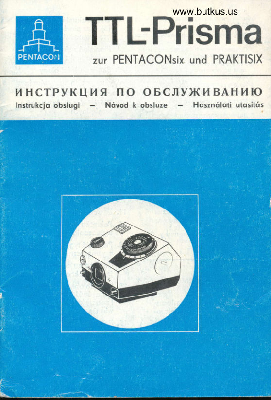
TTL-Prisma----f-il              zur PENTACONs|x und PRAKTISIX[s[p[|
BEDIENUNGSANLEITUNG
lnstructions for Use - Mode d' emploi -  Instrucciones poro el uso
View original page 1
Page 3 · Read text
Der TTL-Prismenoufsotz wird on Stelle des Lichtschochtes oder des
iiblichen Umkehrprismos in Verbindung mit der PENTACONsix
oder der PRAKTISIX verwendet. Er ermoglicht die Belichtungsmes-
sung noch dem modernen, technisch exokten InnenmeBverfohrerr
ols Teilintegrolmessung. Dobei werden olle die Belichtung beein-
flussenden Foktoren outomotisch beriicksichtigt. Korrekturwerte,
wie sie z. B. bei Nohoufnohmen oder bei Verwendung von Licht-
filtern erforderlich sind, entfollen.
Wir bitten Sie, die Hinweise dieser Anleitung sorgfciltig zu be-
ochten. Schciden, die durch unsochgemciBe Behondlung der MeB-
einrichtung entstehen, liegen ouBeiholb unserer Gorontieleistung.

                             !


                                                             aa


                             www.butkus.us
View original page 3Page 5 · Read text
Bezeidrnung der Eedlenteile         llomenclolure des orgones de commonde:
  I   Scholtcr fOr MeBstromkrels                                    I  Commutoteur du clrcult de mesure
 2  Zelgerfenster mtt Zelger und Festmo*e      2  Fenttre de locture ovec otgullle et
                                                 repdre flxe     Elnstcllknopf,                        ous Innentell mtt                bestehend 3                                                 de rrigloge comportont une pqrtle                                                 (4)     3  Bouton    Skolen                      Belichtungszeltenrtng           (5) und                                                             Int6rleure ovec 6cfielles (5) et une bogue 4  Bellchtungszeltenrlng                          des temps de pose (41
 5  Filmempftndltclrkeitsskolen                      1  Bogue des temps de pose
 6  Morke zum Elnstellen der Filmempftnd-        5  Echelles de senstbilit6
       lrcfiketr                                  6  Rep€re pour I'olftchoge de lo senslblllt6
 7  Blendenring mtt Skolo der Blendenzohlen      7  Bogue de dtophrogme ovec 6chelle en
  I  Morke f0r Messung mtt Aufnohmeblende          tndlces de dlophrogme                                                       pour                                                                 ovec le dio-                                                                  lo mesure                                                          I  RepBre                         ftlr Blendenzohlen. 9  Elnstellmorke                                              phrogme                                                          de vue                                               de prlse     Bellchtungszeiten                   oder Morke 8                                               9  Repdre pour lndtces de dlophrogme,
to  Okulorfossung                               temps de pose ou repire 8
t1   OkulcrverschluS                             l0  Monture d'oculolre
12  Bedienungsknopf f0r Okulorverschlul]      11 Vc let d'oculolre
t3   RlegelkniSpfe                       12 Bouton de ccmmonde du volct d'oculolre
14  Elementenroum  mlt Deckel              13 Boutons de verroullloge
t5  Zetgerfeld mit MeBwerkzelger und        11 Chombre de plle ovec boudlon filet6     Festmorke                                   l5  Chomp d'oscllotion de l'olguille, olguille                                                 et repdre flxe
t6  Morkierung des MeBfeldes lm Sucher      16  D6limitotlon de  l'oire de mesure dons
17  Hondobblendhebel om Aufnohmeobjekttv          le viseur
                                  17  Levler de commonde monuelle du dlo-
                                              phrogme sur I'obJectlf de prlse de vue

  Control ports:                         Denominori6n de los elementos de soruicio:
  I  Swltch knob for meosurtng c:rcult                       I   Interruptor poro el clrculto de medlcl6n
 2 Wtndow showlng meter needle ond         2  Ventonlllo Indlcodoro con lndicodor y
     centerlng mork                              morco ftio
                                               3  Bot6n                                          de groduocl6n,                                                              compu€sto                                                             de lo            knob,                   conslstrng                                  Inner                                        sectlon    Control                           of 3                                                  portc lnterlor                                                                                  (5) y ontllos                                                    con escolor                                                 (4)          scoles                       exposure                              speed     wlth                  (5) ond                                           rlng                                           de tlempos de exposlct6n (4) 4  Erposure speed rlng                         4  Anlllo de tl€mpos de exposltl6n
 5  Fllm speed scoles                           5  Escolos de lo senstbilldod de pellculo
 6  Inder mork for setttng film speeds          6  Morco poro grqduor lo sensibiltdod de
 7  Aperture rtng with scole of f numbers             peliculo
 I   lnder mork for meosurlng wlth lens ot       7  Antllo de dlofrogmo con escolo de los
    toklng operture                              ntmeros de dtofrogmo
                                              Morco poro lo medlci6n con el dlofrogmo 9  Index mork {or f numbers, exposure speeds,       I   fotogroflco
    or mork I                               9  Morco de groduocl6n poro nrimeros de dlo-
t0  Oculor mount                                    frogmo, tl€mpos de exposlcl6n o morco IIt  Mosk for eyeplece of vlewflnder         10 Monduro del oculor
12  Control knob for mork                11 Clerre del oculor
13  Locklng knobs                      12 Boton poro monejor el clerre del oculor
14  Bottery chomber wlth cover             13 Botones de cerroJo                                        Cdmoro                                  14                                              de elementos                                                               con topot5  Sectton           showlng                  meter needle qnd                                                            tndicodor                                  15 Compo                                                           con tndlcodor                                                                              dcl ne-    centerlng             mork                                                conismo de medlci6n y morco fijo
16  Boundory lines ol meosured or€o tn                      I 6 Morcoct6n del compo de medlct6n en el vlsor
     vlewf tnder                        17 Polonco dlofrogmodoro o mono cn el
17  Monuol stop-down lever on toklng lens           objettvo fotogr6flco                              www.butkus.us
View original page 5Page 6 · Read text
The TTL Prism Attochment con be used insteod of the finder hood
or the usuol pentoprism in connection with the PENTACONs|x or
the PRAKTISIX comero. lt enobles portiolly integrol light metering
to be performed, bosed on the modern, technicolly oc_curote inter-
nol meosuring system. All foctors moking ony difference with
regord to the exposure ore outomoticolly token into occount.
Correctior: of exposure volues is no longer necessory, for instonce
in connection with close-up bellows or with filters.
We request you to study these instructions with greo! core, since
we con occept no liobility for ony domoge coused by improper
hondling of the equipment.

L'ensemble de prisme TTL s'emploie en lieu et ploce du copuchon
de vis6e ou du prisme redresseur ordinoire sur le PENTACONsIx
ou sur le PRAKTISIX.  ll permet lo mesure de l'exposition por l'op-
plicotion de lo m6thode moderne, exocte du point de vue techni'
gue, de lo mesure de l'int6rieur, sous forme de mesure portielle-
rnent int6gr6e. Ce proc6d6 tient compte outomotiquement de
tousles focteurs qui influent sur I'exposition.  ll n'est plus n6ces-
soire d'oppliquer les co6fficients de correction qu'exigent, por
 exemple, les prises de vues en mocrophotogrophie ou ovec filtres.
Nous vous prions de lire ottentivement les prescriptions du pr6-
 sent mode d'emploi. Les d6t6riorotions dues d une monipulotion
 inod6quote du dispositif de mesure ne sont pos couvertes por
notre gorontie.


 El oditomento prismdtico TTL se empleo en lugor del conducto de
luz o del prismo inversor corriente en conrbinoci6n con lo PENTA-
 CONsix o de lo PRAKTISIX. Posibilito medir lo exposici6n seg{n
el moderno procedimiento de lo medici6n interior t6cnicomente
exocto en formo de uno medici6n integrol porciol. En ello, outo-
mdticomente se tomon en cuento todos los foctores influyentes en
lo exposici5n. No se requieren volores de correcci6n, necesqrios
 p. ej. en los fotogrofios de cerco o en el empleo de filtros de luz.
Rogomos otenerse estrictomente o los indicociones contenidos en
estos instrucciones, puesto que no cumpliremos con lo gorontio
dodo ol trotorse de monejos incorrectos del dispositivo de medi-
 ci6n.
View original page 6Page 7 · Read text
pefestisen des fn-Piiimenoufsotzes on der Komero- ;fr
 lu1  B.e{e.stige-n om Komerokorper sind die beiden Riegelknopfe (13) gleichzeitig einzudriicken. Dobei wird der Aufsotz ion oben
 ouf die vier Holtebolzen der Komero oufgesetzt. Noch Loslossen
 der Knopfe ist der Aufsotz fest mit der Komero verbunden.
 Bei Verwendung der Bereitschoftstosche zur PENTAcoNsix oder
 PRAKTISIX mit Umkehrprismo konn der TTl-Aufsotz on der
 Komerq' verbleiben.

 How to fix the TTL Prism Attqchment to the comero
To fix the ottochment to the comero, depress the two locking knobs
 (13) simultcneously. Now ploce the ottochment from obove-on the
four connecting bolts of the comero. Leove hold of the knobs, ond
the ottochment is fixed_tightly to the comero. lf the Everreody cose
for PENTACoNsix or PRAKTISIX with pentoprism is being used the
TTL Prism Attochment con remoin on the comero.

Mise en ploce de l'ensembte de prisme TTL sur l'opporeil
Pour plocer I'ensemble de prisme sur I'opporeil, oppuyer simulto-
nEment sur les deux boutons de verrouilloge (13). En m6me temps,
on enfonce, du hout, I'ensemble sur les quotre bourons de moin-
tien de l'opporeil. Lorsqu'on rel6che lo pression sur res boutons,
l'ensemble_de prisme foit solidement corps ovec I'opporeir. En cos
d'emploi du soc "toujours-pr6t" ovec le pENTAC'ONsix ou le
PRAKTISIX muni du prisme, l'ensemble TTL peut rester sur I'oppo-
reil.

sujeci5n del oditomento prismdtico TTL o lo c6moro
Poro lo sujeci6n ol cuerpo de cdmoro es preciso introducir qt
mismo tiempo los dos botones de cerrojo (ts). rn eilo, el odito-
me.nto llego o ponerse desde orribq sobre los cuotro pivotes suje-
todores de lo c6moro. Al soltor los botones, el oditomento que-
dord fijomente unido con lo cdmoro.
Al usor el estuche pronto uso poro lo PENTACONs|x o poro lo
PRAKTISIX con prismo de inversi6n, el oditomento TTL' puede
permonecer en lo c6moro.
                             www.butkus.us
View original page 7Page 9 · Read text
irkungsweise

Dos im TTL-MeBoufsotz  befindliche Pentodochkont-Prismo bietet
ciem Benutzer ein seitenrichtiges,  ouf rechtstehendes Sucherbiid,
dos mit der etwo 2,5-foch vergroBernden Okulorlupe betrochtet
wird. Bei Verwendung des Normolobjektivs von B0 mm Brennweite
ergibt sich eine etwo O,8-foche GesomtvergroBerung des optischen
5,v'stems.
Wie beim Prismenoufsotz ohne MeBeinrichtung  ist die Okulor-
fossung ols Zubeh6rwechselstelle zum Ansetzen von Steckschuh,
Augenmuschel, Korrekturglosfossung, Winkelsucher und Einstell-
fernrohr o usgebildet.

Functioning ond design of the TTL Prism Attochment
The roof-shoped pentoprism incorporoted in the TTL Meter Attoch-
ment reveols to the comero user o correct-sided, upright finder
imoge, viewed through the oculor lens which gives on opproxi-
nrotely 2.5-fold mognificotion. With the stondord 80 mm lens in
 the comero, this meons o totol mognificotion of the opticol system
of obout 0.8 times.
Like on the pentoprism without exposure meter, the mou'nt of the
oculor is designed to occept extro devices, such os Accessory Shoe,
Eyecup, Mount for correcting lens, Angle Finder, or Focusing Teles-
cope.

Fonctionnement et montqge de l'ensemble
de prisme TTL
 Ie pentoprisme en toit qui se trouve dons l'ensemble TTL fournit
une imoge de vis6e redress6e lot6rolement et verticolement, que
 I'on peut exominer sous lo loupe d'oculoire donnont environ 2,5
gi'ossissements. Lorsqu'on utilise I'objectif normol de 80 mm de
focole, on obtient un grossissement d'ensemble de 0,8x du sys-
tdme optique.
 Comme pour le prisme soirs dispositif de mesure de l'exposition,
 c'est lo monture d'oculoire qui sert de support pour occessoires
 pour le plocement de lo griffe d occessoires, de I'oeilldre, de lo
 monture pour verres correcteurs, du viseui" coud6 et de lo lune+te
de vis6e.
 4                           www.butkus.us
View original page 9
Page 10 · Read text
Funcionomiento y diseffo del oditomento
prismdtico TTL
El, prismo pentogonol en el oditomento de medici6n TTL brinds      I
 ol usuorio uno imogen derecho y de lodos no invertidos en el visor
que se observo con lo lupo oculor de 2,s oumentos. Al utilizor-ei              II
objetivo normol de 80 mm de distoncio focol r"tulto un oumento                      itotol de unos 0,8 veces del sistemo 6ptico.
Lo mismo gue en el.prismo pentogonot sin dispositivo de medici6n,                  It
lo monturo del oculor sirve de luggr de combio poro odoptor lo        Izopoto de enchufe, lo concho-oculor, lo monturo poro cristoles
correctores de lo visto, el visor ongulor y el onteojo de enfoque.
View original page 10
Page 11 · Read text
MeBprinzip
Die fotoelektrische MeBeinrichtdng des TTL:Aufsotzes'orbeitet noch
dem Prinzip der Teilintegrolmessung, d. h., es wird im Bereich
eines im Sucher gekennzeichneten  Feldes von 25 mm Durchmesser
(16) integrierend gemessen. Der Vorteil dieser Anordnung besteht
dorin, bildwichtige Portien besonders beriicksichtigen zu k6nnen.
Die MeBeinrichtung ist so oufgebout, doB dos MeBlicht on der
biidoufrichtenden Flciche des Umkehrprismos entnommen und dem
CdS-Fotowiderstond zugeleitet wird. Als Energiequelle dient ein
Quecksilberoxidelement vom Typ Mollory PX 13.
Die Messung selbst ist schnell und einfoch ouszufiihren, do ledig-
fich der Teiger des MeBwerkes durch Drehen des Einstellknopfes
(3) einer Festmorke gegentiberzustellen ist. Dobei konn der MeB-
werkzeiger wohlweise innerholb des Zeigerfeldes (15) neben dem
Sucherfeld beim Einblick in dos Okulor oder durch dos Zeiger'
fenster (2) ouf der Oberseite des TTl-Aufsotzes beobochtet wer-
den.
Der TTl-Aufsotz bietet zwei Moglichkeiterr der Innenmessung:
      o) dos Messen mit Offenblende,
      b) dos Messen mit Aufnohmeblende.
Skqlen flir Filmempfindlichkeit, Blendenzohlen und Belichtungszeit
Am Knopf (g) befinden sich die beiden Skolen  fiir die Filmempfind-
                                                                        Einstell-lichkeit. Der Ring ( ) trcigt die Belichtungszeiten und diemorke (6) zum Einstellen der Filmempfindlichkeit' Auf dem dorun-
terliegenden vom Knopf (3) getrennten Ring (7) sind die Blenden-
zohlen sowie die Einstellmorke 8 ongegeben'
Filmempf    i ndlichkeitssko len
Der Einstellknopf (3) besitzt zwei Skolen zum Einstellen der Film-
empfindlichkeit noch DIN- und ASA-Werten. Durch oxioles Anhe-
ben des Belichtungszeitenringes (4) wird ouf die dem verwendeten
Aufnohmemoteriol entsprechlnde Empfindlichkeit  eingestellt. Der
Ring (a) rostet bei jedem DIN-Wert - d. h,, ouch bei den Zwi-schlnwerten der ouf den Skolen ongegebenen Werte -  ein.
Scirntliche in der folgencien Tobelle ongegebenen Werte konnen
om TTl-Aufsotz eingestellt werden.
6
                             www.butkus.us
View original page 11Page 13 · Read text
Die im Druck hervorgehobenen Empfindlichkeitswerte stellen die
 ouf den Skolen ongegebenen Zohlen dor.
     DIN    ASA        DIN
           9             d              2l              100
          10             8            22             125
            11              10             23             160
          12            l2            21            200
          13             16             25             250
          14            20             26            320
         15           2s            27            f00
          16           32             28            500
         17           40             29             650
          t8            50             30            800
          19            64                31                    1 000
         20            80            32            1250
                                    33            r600
 Vt/ird in der Komero die unmqttierte Bildfeldlinse 207350 verwen-
 det, so ist die Filmcrnpfindlichkeit mit 2 DIN weniger einzustellen.
 Die Energiequelle
AJs. Energiequelle_  ftir die fotcelektrische MeBeinrichtung wird ein
Mollory-Element PX 13 verwendet, Es wird noch Abschriuben des
Deckels mit Hilfe einer Mlinze in den seitlich om TTL-Aufsotz
befindlichen Elementroum (1+) eingesetzt. Der mit dem pluszeichen
(+)gekennzeichnete Boden des Elements zeigt dobei noch ouBen
zlrm Deckel, der ouf seiner lnnenseite dos gleiche Zeichen trcigt.
Dos Ein- und Ausscholten der BelichtungsmeBeinrichtung  wird mit
dem Knopf (1) vorgenommen. wird diesei Knopf noch recfits bis zum
Anschlog gedreht, so dcB der dorouf ongebrochte pfeil ouf den
gr.tinen Morkierungspunkt zeigt, so ist die MeBeinrichtung einge-
scho ltet.
Der rote Punkt kennzeichnet die Ausscholtstellung. Es ist dorouf zu
ochten, doB noch Beendigung der Belichtunqrr-.ssunq der Schol-
terknopf wieder durch Linksdrehen in stellung ,Au's" gebrochtwird.
Do bei der MeBeinrichtung eine Briickenschortung ongewondt wird,
ist eine Kontrolleinrichtung  fi.ir die Betriebssponn-ung  iicht notwen-
{yg. Es_empfiehlt sich jedbch, noch etwo eln bis iwei Johren dosPX-13-Element gegen ein neues zu ersetzen. Dos verbrouchte
Quecksilberoxidelement  dorf nicht ins Feuer geworfen werden, do
E.vplosionsgefohr  besteht.
8                            www.butkus.us
View original page 13Page 14 · Read text
The Exposure Meter System
The measuring principle
The photoelectric exposure meter in the TTL Attochment works oc-
cording to the principle of portiolly integrol meosuring, i. e., meos-
uring tokes ploce integrolly within the oreo, 25 mm in diometer
(15), os morked in the viewfinder. This orrongement hos the od-
vontoge of enobling speciol ollowonce to be mode for importont
sections o{ the imoge,
The exposure meter system is constructed in such monner thot the
 light required for meosuring is picked up on the imoge-erecting
surfoce of the pentoprism ond conducted to the CdS photo re-
sistor, Power source is o mercury-oxide bottery Mollory PX 13.
The metering process is quick ond simple. The meter needle hos
only to be moved to coincide with o fixed mork by rotqtion of
control knob (3).
Movement of the meter needle moy be wotched either through the
oculor, in the section (i5) next to the viewfinder, or in the windour
(2) on the top of the TTL Attochment.
There ore two possibilities of internol meosuring with the TTL
Attochment:
   o) meosuring with lens of full operture,
   b) meosuring with lens ot toking operture.
Scqles for film speed, f stops, onC exposure speed
On knob (3) ore the two scoles indicoting the film speeds. Ring
(4) beors the exposure speed numbers ond the index mork (6)
for setting the film speeds. The seporote ring (7) below knob (3)     lf
shows the f numbers ond the index mork 8.
Film speed scoles
Control knob (3) is provided wiih two scoles for setting the film
speeds in DIN ond ASA volues. Lift the exposure speed ring (4) in
oxiol direction ond move it to set the speed of the negotive
moteriol in the comero. Ring (a) clicks in ot every DIN volue, olso
ot the intermediote stops between the volues on the scoles.
All the volues listed in the toble below ore odjustoble on the TTL
Attochment.
The film speed volues printed in speciol type indicote the num-
bers morked on the scoles.                 ej
View original page 14Page 15 · Read text
DIN                      DIN         ASA
      96                             21              100     10              I             22             125
     11            10             23             160
     12            12             24            200
     13            16             25             250
     14           20             26             320
     15           25             27            400
     16           32             28            500
     17           40             29             650
     18           50             30             800
                                                                                            1 000     19           64                31
     20           80             32            1250
                                    33            r600
 lf the cleor-gloss field lens 207350 is being used in the comero,
the film speed setting hos to be lower by 2 DlN.
The power source
Power source for the photoelectric metering system is o Mollory
bottery of the PX 13 type. The cover of the bottery chomber (14)
on the side of the TTL Attochment is u'nscrewed with the oid of
c coin ond the bottery inserted. The plote of the bottery beoring
the plus sign (*)  must foce the cover which beors the some sign
on the inside.
The exposure meter device is switched on ond off by meons of
knob (1). Turn the knob to the right os for os it will go, so thot
its orrow points to the green mork, ond the exposure meter  is
sraiitched on.
The red dot indicotes the "off" position' After the lightmeter reod-
ing hos been token, pleose do not forget to switch off by moving
the knob bock in the onti-clockwise direction.
A bridge circuit is employed in the metering system, thus elimi-
noting the necessity for checking the working voltoge of the bot-
tery. Nevertheless, it is odvisoble to insert o new PX 13 bottery
ofter 1 or 2 yeors. Owing to donger of explosion, the discorded
mercury oxide bottery must not be thrown into the fire'


 t0                           www.butkus.us
View original page 15Page 16 · Read text
Le dispositif de mesure de l'exposition
Le principe
Le dispositif photo6lectrique de l'ensemble TTL est bos6 sur le
principe de lo mesure poitiellement. int6gr6e,..-d-g' que, sur une      t
                                                                          estIon.'J" 25 mm de diomAtre (16) d6limit6e dons le viseur, il
proc6de o une mesure por int6grotion. Ce systdme.offre  I'ovon-
iog" a" permettre de tenir compte sp6ciolement..de  porties du
sujet qui sont essentielles pour lo composition de I'imoge'
Le dispositif de mesure est mont6 de moni6re telle que lo lumidre                                                         ipotii.ipont a lq mesure est copt6e sur lo foce redresseuse du
                                                                                                                                                                                                                                    rllbiirr"' et, de ld, dirig6e vers lo photor6sistonce ou CdS. Le cou'ront est fourni por rtiu pile d l'oxyde de mercure du type Mollory
PX 13, Lo mesure proprement dite s'effectue focilement et ropide-
ment, puisqu'il sufiit d'orene]. l'oiguille de l'instrument de mesure
 ;;  r;g';ri d'un repdre fixe en toulnont le bouton de r6gloge (3)'pour Ielo, on p"ui, d volont6, observer l'oiguille d trovers l'ocu-
 toir", Jont les'limiies de son chomp d'oscillotion (15), d c6t6 du
.no.p de vis6e, ou por lo fenetre de lecture (2) dons le hout deiense'mble TTL. L'ensemble TTL offre deux possibilit6s de mesure
 irrt6rieure   :
      o) lo mesure d pleirre ouvertu're du diophrogme,
      b) lo mesure ovec diophrogme de prise de vue'
 Echelles de sensibilit6, d'indices de diophrogme et de temps
de pose
 Le bouton (3) porte les deux 6chelles de sensibilit6. Lo bogue (4)
 porte les temps de pose et le repdle (6) dg.r6gloge de lo sensi-
 bitite. Lo bog'ue (7), situ6e sous lo bogue (a) et s6por6e du bou-
 ton (3), portJ les indices de diophrogme oinsi que le repdre B'
 Echelles de sensibilit6
 Le bouton de r6gloge (3) porte deux echelles de sensibilit6, en
 voleurs DIN et en n-SR' On souldve lo bogue des temps de pose,
 (4) selon son oxe et l'on rdgle sur o sensibilit6 correspondonte,oul
 mot6riel photosensible utilis6, Lo bogue (4) s'encronte.pour  ..ho-l
 que voleur DlN, c'est-d-dire qu'elle s'encronte oussi sur les voleurs'
 interm6dioires comprises entre les voleurs grov6es sur les 6chelles.
 Toutes les voleurs reprises ou tobleou ci-dessous peuvent 6tre
 of{ich6es sur l'ensemble TTL'
                                                                                                Il
View original page 16Page 17 · Read text
Celles qui sont soulign6es ou tobleou sont celles qui sont gro-
v6es sur les 6chelles de l'instrument.
        DIN        ASA         DIN
      96                            2l              100
     10            8             22             125
     11            10             23             160
     12           12             2l            200
     13            16             25             250
     14           20             26             320                 1     15          25            27            400                                                                                                                         i
     16          32             28            500
     17           40             29            650
     18          50            30            800
     19          64               31             1000
     20           80             32            1250
                                    33            r600
Si I'on emploie sur I'opporeil une lentille de chomp cloire 207350,
lo sensibilit6 offich6e doit 6tre r6duite de 2 DlN.
Lo source d'6nergie
On emploie comme source d'6nergie pour le dispositif de mesure
photo6lectrique une pile Mollory PX 13. Aprds ovoir d6viss6 d    1
I'oide d'une pi6ce de monnoie le bouchon filet6 de lq, chombre de
pile (1a) situ6e sur le c6t6 de l'ensemble TTL, on d6pose lo  pile
dons son logement. Le tond de lo pile, morqu6 du signe (*)  po-          Iisitif, doit 6tre dirig6 vers, l'ext6rieur, foce ou couvercle, qui porte
le mOme signe sur sq foce int6rieure.
Lo mise en circuit et hors-circuit du dispositif de mesure se foit ou
moyen du bouton (1). Lorsqu'on tourne ce bouton d fond vers la
droite, de monidre d ce que sq, fldche soit en regord du point de
repdre vert, le dispositif de mesure enclench6. Le point rouge indi-
que lo mise hors-circuit. Lo mesure termin6e, on ouro bien soin de
tourner le bouton vers lo gouche sur so position hors-circuit.
Un circuit en pont oyont 6t6 utilis6 pour le dispositif de mesure,
tout dispositif de contr6le de lo tension de service est inutile.  ll
est d conseiller, toutefois, de remplocer lo pile PX 13 por une pile
froiche oprds 1 ou 2 ons. On 6vitero de jeter o pile usog6e ou
feu, en roison du donger d'explosion.

 l2                            www.butkus.us
View original page 17Page 19 · Read text
Escolos poro lo sensibilidod de peliculo
 El bot6n de groduoci6n (3) tiene dos escoros poro ro groduoci6n
 de lo sensibilidod de. pe.liculo segrin vorores ottt v ASA. po. ele- voci6n oxiol del on,illo de los tie-mpos de explosi.ian-(+),; g;;- duord o lo sensibilidod correspondiente ol moteriol roiogrdii.L.
  El onillo (4) es retenido    .odo volor DlN, .t J".ii tombi6n en  los volores intermedios de"nlos volores indicodos sobie los escolos.
 En el oditomento TTL pueden groduorse todos los volores indi-
 codos en lo tqblo sigu,iente;
 Los volores de sensibilidod subroyodos representon los volores
 indicodos sobre los escolos
      DIN    ASA        DIN         ASA
             I         62r                         100
           10        822                       125
            11       10            23             160
           12       12            24             200
          13       16            25             250
          14       20            26             320
          t5       25            27            400
          16       32            28            500
          17       40            29             650
          r8       50           30             800
          19       64              31                      1 000
         20         80'           32            1250
                                    33            1600
Al utilizor en lo cdmoro ro tente der cornpo de imogen no ms-
 teodq 207350, es menester groduor lo senfiLiria"J JJ peliculo o un volor disminuido por 2 DlN,
Lo fuente de energio
como fuente de energio poro er dispositivo de medici6n foto-
el6ctrico se empleo un eremento pX ts oe voirorv. s.  introduce
en lo cdmoro de elemento (14) que se encuentro roterolmente en
el oditomento TTL y cuyo topo se desenrosco con ouxirio de uno
monedo. En ello, el fondo del elemento morcodo con el signopositivo (+) sefrolo hocio, fuero en direcci6n de lo topo que llivoen su lodo interior el mismo signo.
74                            www.butkus.us
View original page 19Page 20 · Read text
Lo conexi6n y desconexi6n del dispositivo exposim6trico se efec-
    t(o con el bot6n (1). Al giror dicho bot6n hocio lo derecho hosto
     el tope, de modo que lo flecho sobre dicho bot6n seffolo hocio
     el punto morcodor verde, es pruebo de hober conectodo el dis-
      positivo de medici5n.
     El punto rojo morco lo posici6n de desconexi5n. Uno vez medido
     el tiempo de exposici6n, hoy que fijorse en giror el bot6n inter-
     ruptor otro vez hocio lo izquierdo o lo posici6n "Aus" (desconec-
     tcdo).
I    errPuestopuente,quenoenseel necesitodispositivoun dedispositivomedici6ndesecontroloplicoporou'noloconexi6ntensi6n
    de servicio, No obstonte, es recomendoble reemplozor el elemento
   PX 13 por otro nuevo despu6s de 1 o 2 ofros, EI elemento de
I    6r.ido de mercurio consumido no debe tirorse ol fuego por el
     peligro de explosi6n,


                                                                       t5
View original page 20Page 21 · Read text
Belichtungsmessung             -=*frflfr+ilff4l
A Messen mit Offenblende
1. Einstellen der Filmempfindlichkeit. Dqzu AuBenring (4) des
   Knopfes (3) bis zum Anschlog noch oben ziehen und gleichzei-
    tig drehen, bis die weiBe Morke (6) ouf den Empfindlichkeits-
   wert des verwendeten Auf nohmemoteriols zeigt. Der Ring
                                                                                                                                                                                                                                                                                                                                         ,   rostet beim Zurtickfohren ein. Dobei konnen Zwischenwerte
   zwischen den ouf der Skole ongegebenen Empfindlichkeitswer-
   ten eingestellt werden (s. dozu Tobelle Seite 8).
2. Durch Drehen des Blendenringes (7) wird die Moximol6ffnung
   des verwendeten Objektivs (kleinste Blendenzohl z. B. 2,8) der
   Morkierung (9) gegeni.ibergestellt.  Sie rostet dort ein. Zwischen-
   werte sind ebenfolls einstellbor.
3. VerschluB der Komero sponnen.
4. MeBeinrichtung einscholten durch Rechtsdrehen des Knopfes                                        l
    (1): Pfeil zeigt ouf die grline Morkierung.                                                                                                                                                                                                  l
5. Komero so ouf den Aufnohmegegenstond richten, doB bildwich-
   tige Portien innerholb des im Sucher gekennzeichneten MeB-
   feldes (16) liegen. MeBwerkzeiger durch Drehen des Einstell-     |
   knopfes (3) ouf Mitte der Einstellmorke einstellen, Dobei konn
   die Zeigerbeobochtung beim Einblicken in dos Okulor innerholb
   des MeBfeldes (15) neben dem Sucherbild oder von ouBen
   durch dos Zeigerfenster (2') erfolgen.                                                                                                     I
   lnletzteremFolleistesbesondersbeiungUnstigenBe|euch.
    tungsverhciltnissen  (direktes Licht ouf dos Okulor) erforderlich,
   die Okulor6ffnung durch Linksdrehen des Bedienungsknopfes
   (121 zu verschlieBen.  '  Auch bei der Zeigerbeobochtung durch dos Okulor ist es zu
   empfehlen, die mitgelieferte Lichtschutzkoppe in die Okulor-
   fossung (10) einzusetzen, domit bei direkter Beleuchtung des
   Okulors durch storke Lichtquellen keine Verfcilschung des MeB-
   ergebnisses ouftreten konn.
6. Noch der Messung ergeben die om Blendenring (7) und Belich-
    tungszeitenring (4) sich gegeni.iberstehenden  Zohlen, Blende-
   Zeit-Kombinotion, die richtige Belichtung.                                                   I
  Es wird diejenige Kombinotion ousgewdhlt und om Belich-  |
   tungszeiteinstellknopf der Komero und om Blendenring des
   Objektivs eingestellt, die der Motiveigenort om besten ent-
r6                          www.butkus.us
View original page 21Page 22 · Read text
r"4".
                                                                                          t-T4?F


.s/* ';-"e*
      spricht. Bei objekten mit schnelle_r Bewegu.ng wird z. B. eine
     kurze Belichtungszeit bei kleiner Blendenzohl gewdhlt werden,
     wcihrend von einer groBeren Blendenzohl bei ldngerer Belich-
     tungszeit ousgegong:en wird, wenn groBe Schcirfentiefe erfor-
      derlich ist.
    Es ist zu beochten, doB Zwischenwerte nicht om Zeiteinstell-
     knopf der Komero, sondern nur om Blendenring des objektivs
     einzustellen  sind.
                                                                         rote  7. MeBeinrichtung durch Linksdrehen von Knopf (1) ouf
    Morke ousscholten.

  Meosuring the exPosure time
 A Meosuring of full lens oPerture
  1. setting the film speed. This is done by lifting. up outer ring  (a.r.
      of knJU (S) os foi os it will go, ot the some time turning it until
     the white mork (6) points to the speed volue of the negotive
                                                                  17
View original page 22Page 23 · Read text
moteriol in the comero. The ring clicks in when dropped bock.
   Also intermediote volues between the numerols on the scole
   moy be selected. (Pleose note toble on poge 10).
2.  By rototion of operture ring (7) the widest operture of the lens
    in the comero (smollest diophrogm numerol, e. g.2.8) hos to
   be brought to coincide with index mork (9), where it clicks in.
   AIso here intermediote volues ore odjustoble.
3. Cock the comero shutter.
4.  Switch on the metering system by clockwise rototion of knob
    (1): Arrow points to green mork.
5.  Direct the comero towords the object to be photogrophed so
   thot importont sections of the imoge oppeor within the boun-
   dory lines of the oreo (16) morked in the viewfinder. Move
   meter needle to the centering mork by rototion of control knob
    (3). Movement of the needle moy be wotched either through
   the oculqr, in the section (15) next to the viewfinder, or in the
   window (2) on the outside. In the lotter cose, especiolly under
   unfovouroble lighting conditions (light folling directly on to
   the oculor), the mosk of the oculor hos to be moved in by
    rototion of knob (12) to the right.
   Also when wotching the meter needle through the oculor, it  is
   odvisoble to insert the lighthood supplied with the equipment
    into the oculor mount (10) to ovoid getting incorrect reodings
   which moy result from intense light folling stroight on to the
    oculor.
  The meosuring procedure leods to operture/speed combino-
    tions formed by the volues focing eoch other on operture ring
    (7) ond exposure speed ring (4), oll of which give on equolly
    correct exposure.
   The combinotion most suitoble to the chorocter of the object
     is then chosen ond tronsferred to the speed setting knob on the
   comero ond to the diophrogm setting ring on the lens mount.
   Ropidly moving obj'ects, for instonce, will be token with o fost
    shutter speed setting ond o smoll diophrogm numerol, whe-
    reos o lorger diophrogm numerol ond o longer exposure time
    will be proper if greoter depth of field is required.
   Pleose note thot intermediote volues connot be set on the
   speed knob of the comero but only on the diophrogm ring of
   the lens mount.
7. Switch off the metering system by onti-clockwise movement of
   knob (1) to the red mork.
                               www.butkus.us
View original page 23Page 24 · Read text
Mesure de l'exposition
A Mesure d pteine ouverture du diophrogme
1.  Affichoge de lo sensibilit6. A cet effet, tirer d fond vers le
   hout lo- bogue ext6rieure (4) du bouton (3) et,. en m6me
   temps, lo toi.rrner jusq'o ce que le repdre blonc.(6) se trouve
  en iegord de I'indice de sensibilit6 du mot6riel de prise de
   uues u]tilis6. Lo bogue s'encronte lorsqu'on lo ldche. Le 169loge
   peut se foire ouisi sur les voleurs internr6dioires comprises
    entre celles qui sont grov6es sur l'6chelle (voir tobleou p. 12).
  En tournont lo bogue des diophrogmes (7), ossurer lo plus
   gronde ouverture de l'oblectif utilis6 (indice- le plus bo.s, p' ex'
    Z,B1 qu. I'on offiche en regord du rep,ire- (9). Loisser- s'encron-
   ter'lo bogue. on peut oulsi 169ler sur des vqleurs interm6di-
    o ires.
3.  Armer l'obturoteur de I'opPoreil.
4.  Enclencher le dispositif de mesure en tournont le bouton (1)
    vers lo droite: lo flGche se met en regord du repdre vert.
5.  Diriger l'opporeil vers le sujet de monidre telle que les p.orties
    esse-ntielles'pour  l'6loborotion de l'imoge se trouvent d I'int6-
   rieur de l'oire de mesure (16) d6limit6e dons le viseur.
   Amener I'oiguille de mesure ou centre du repdre de 169loge
   en tournont le bouton (3)' Au cours de cette op6rotion, on peut
    observer le mouvement de I'oiguille d l'int6rieur de son chomp
    d'oscillotion (15) d c6t6 de l'imoge de vis6e en regordont d
   trovers I'oculoire, ou de I'ext6rieur, por lo fenetre de lecture
    (2). Dons ce dernier cos, il fout, surtout lorsque les conditions
   d'6cloiroge sont d6fovorobles (lumi6re directe froppont l'ocu-
    loire) ob-turer I'ouverture de l'oculoire en tournont le bouton
    (12) vers lo gouche. Et m6me lorsqu'on observe. I'oiguille d
    irouurr I'oculolre,  il est d recommonder d'ins6rer dons lo mon-
    ture de l'oculoire (10) le mosque d'interception de lo lumidre
    fourni ovec I'opporeil, ofin que le r6sultot de lo mesure ne
    puisse 6tre fouss6 por de fortes sources de lumidre qui 6cloire-
    roient directement l'oculoire.
   Apras lo mesure, les voleurs qui se font foce sur les bogues du
   diophrogme (7) et des temps de pose (4) forment d.es combi-
    noisons-temps de pose - diophrogme qui toutes donnent lo
   m6me exposition exocte.
                                                                 19
View original page 24Page 25 · Read text
On choisit celle de ces combinoisons qui convient le mieux d
    lo noture du sujet et on en reporte les 6l6ments sur le bouton
   des temps de pose de I'opporeil et sur lo bogue du diophrog-
  me de l'objectif. Pour les sujets onim6s d'un mouvement ro-
    pide, on odoptero, p.€X,, un temps de pose bref et un foible
    indice de diophrogme, tondis qu'on choisiro un indice de dio-
   phrogme 6lev6 et un temps de pose plus long lorsqu'on d6si-
    rero une profondeur de chomp plus 6tendue.
  On ne perdro pos de vue que I'on ne peut pos officher de vo-
    leurs interm6dioires sur le bouton des temps de pose de l'oppo-
     reil, mois uniquement por lo bogue du diophrogme de l'objectif.
7. Mettre hors-circuit le dispositif de mesure en tournorrt le bou-
   ton ('l) vers lo gouche sur le repdre rouge.
Medici6n de lo exposici5n  t
A Medici6n con el diofrogmo obierto
1. Groduoci6n de lo sensibilidod de peliculo. Poro ello, tiror el
   onillo exterior (a) del bot6n (3) hociq orribo, hosto el tope y
    girorle ol mismo tiempo hosto que lo morco blonco (6) indi-
   que el volor de sensibilidod del moteriol fotogrdfico empleocio.
    El onillo llego o enclovor ol dejorle volver. En ello, es posible
   groduor volores intermedios entre los volores de sensibilidod
   indicodos sobre lo escolo (poro ello, veose lo toblo de lo
   pdsino (14),
2. Por giro del onillo de diofrogmo (7) se hoce coincidir lo
   m6ximo oberturo del objetivo utilizodo (n(mero de diofrogmo
  m6s pequeffo, p.ej. 2,8) con lo morco (9), En esto posici6n
   llego o enclovor. Asimismo, es posible groduor volores inter-
    medios.
3. Armor el obturodor de lo c6moro.
4. Conector el dispositivo de medici6n por giro hocio lo derecho
   del bot6n (1): Lo flecho indico hocio lo, morco verde.
5. Dirigir lo c6moro de tol monero hocio el objeto o fotogrofior
   que los porte importontes de lo imogen se encuentren dentro
   del compo de medici5n (16) morcodo en el visor. Groduor e!
   indicodor del meconismo de medido por giro del bot6n de
   groduoci6n (3) ol centro de lo morco' de groduoci5n, En ello,
   se puede miror por el oculor poro observor el indicodor dentro
   del compo de medici6n (15) ol lodo de lo imogen en el visor
   o desde fuero por lo ventonillo del indicodor (2).
20                            www.butkus.us
View original page 25Related documents and language editions
From the M. Butkus archive. Original publisher and archive notices are retained.
Check the model and edition against your equipment.
PDF verified 2026-10-10.