Flashes & lighting
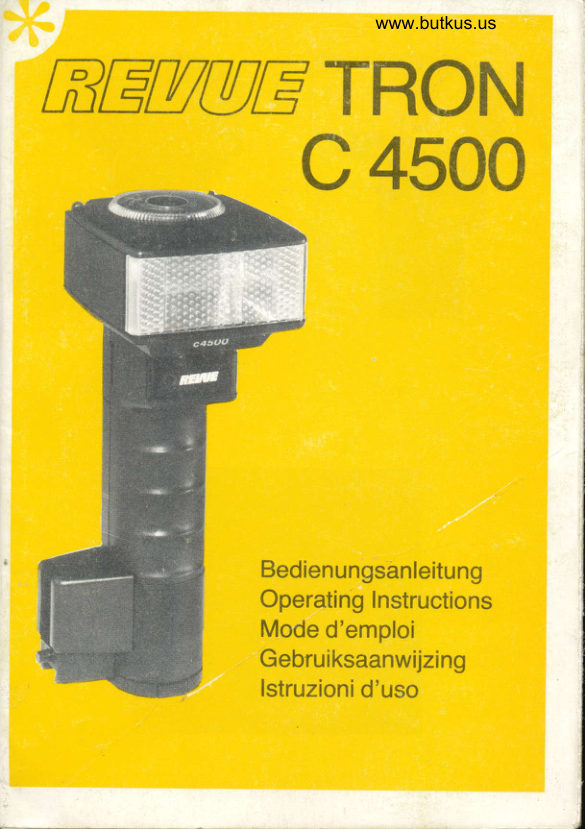
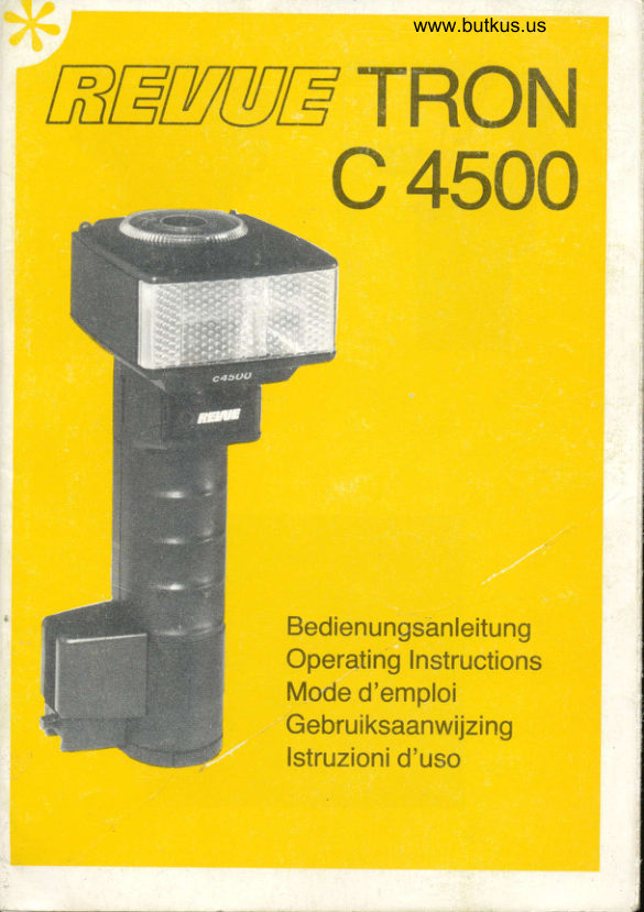
REVUE TRON C4500 User manual
User manual for REVUE TRON C4500. 21 pages in English. Read the original PDF, download or print a copy without registration.
21 pagesEnglish3.1 MB PDF
Loading your manual…Open PDF directly
Document details
- Brand
- Revue
- Model / document
- REVUE TRON C4500
- Document type
- User manual
- Language
- English
- Pages
- 21
- File size
- 3.1 MB
- Category
- Flashes & lighting
- Document date
- Not specified in catalog
Search available document text
Find a term, then jump to its page in the original PDF. Image-only pages may not be searchable; check the PDF for exact wording and diagrams.
Page 1 · Read text
www.butkus.us
REAAtr TRON
      c 4500


                   Bedienungsanleitung
                    Operating Instructions
               Mode d'emploi
                    Gebruiksaanwijzing
                      lstruzionid'uso
View original page 1Page 2 · Read text
Digitally signed by Mike Butkus
                                   DN: cn=Mike Butkus, o=Butkus camera
                                       manuals, ou=butkus.org,Mike Butkus  email=mike@butkus.org, c=US
                                         Date: 2022.05.28 15:41:53 -04'00'
View original page 2Page 4 · Read text
Venmo @mike-butkus-camera  Ph. 2083
PayPal Name  Lynn@butkus.org      www.PayPal.me/lynnbutkus
View original page 4
Page 6 · Read text
www.butkus.us
Sonderzu behor/Optional extras/Accessoi res/
Speciale accessoires/Accessori speciale
View original page 6
Page 7 · Read text
Contents
       1.   Summaryof specifications/Technical data/Guide
             number table
       2.   REVUEtron c 4500 features
       3.   General instructions and explanations
      3.1 Power suPPlY
      3.2 Computer operation
      3.3  Trial flash indicator
      3.4 Bounced light
      3.5  lllumination

                                                                                                                              .      3.6  Synchronization
       4.    Prior to flashing
                                               on the left of the       4.1  Modification for installing the camera
                flash unit
       4.2  Switching the unit on
       5.   Manual flash oPeration
       5.1  Flashing with winder cameras
       6.   Flashing with computer (operating ranges)
       7.   Flashing with wide angle attachmen
       8.   Taking backlight shots
       9.   Optional extras (Fig @. @)
      10.  Care and maintenance


,       1g
t
View original page 7Page 8 · Read text
www.butkus.us
 1. Summary of specifications

 Fig. "A" Rear view
O Carrylng eyelets
@ Manualfiring switch
@ On/of switch
@ Flash ready light
@ Switch - winder/normal operation
@ Trial flash indicator
@ Control centre selector disc
 Fig. "8" Front view
@ Sync cord socket
@ Sensor
@ Reflecto
Fig. "C" Control centre/aperture calculator disc
@ otruunSA film speed scate
@ Selector disc
@ Distance scale "winder"
@ Index mark for operating range, using wide angle attach-
   ment
@ Index line for f-number/distance
@ Index mark for apertures and operational mode
@ Distance scale in metres
@ Diaphragm scale
@ Film speed setting knob
@ Mark for manual operating mode
@ Index mark for film speed
Fig. "D" Holding block
@ HotOing btock
@ Locking knob for bracket
@ Quict< release device


                                                           19
View original page 8Page 9 · Read text
Fig. "E" Battery holder
   @ Catches for securing the battery holder on the flash unit
          Opening the battery holder   @
         Fig. "F" Bracket
    @ rixing screw
       @t/0" and 3/e" camera thread
       @,/0" knurled screw
       Hg. "G" Unit combination ready for firing
         Fig. "H" Scheme for remounting the bracket
    @ trtut
    @ fixing screw for holding block
    @ rixing screw for quick release device
       @lgntening strap
         Fig. "1" Operating ranges


       20
t
View original page 9Page 10 · Read text
www.butkus.us
Technical Data

Guide number using DIN 21
(ASA 100) film:             45
lllumination:            approx. 620 horizontal,
                                    41" vedical
                                                  gOoAdjustable reflector:       horizontal 3600, vertical
                               (locks in 6 settings)
Colour temperature:    approx. 5600 K
Computer with 5 working
apertures:              DIN 21IASA 100 film:
                     2.8-4-5.6-8-11
Flash duration:            approx. 1/300. to 1/25000 sec.
Flash duration during winder
operation**:            approx. 1/12000 sec.
Recycling time, approx.:   Alkaline manganese batt.
                                 13. - 0.3 sec.
                          NiCad pack *"* 7* - 0.3 sec.
during winder operation  max. 2 flashes/sec.
                                 (only with NiCad pack)
Number of flashes, approx.: Alkaline mang. batt.
                             120. -2600
                          NiCad pack *** 50. - 2000
Power sources:          6 alkaline manganese pen-
                                    light batteries
                          NiCad pack ***
Dimensions:          247 x 92 x 102 mm
                    (HxWxD) approx.
Weight:                  approx. 600 g,
                             without batteries
View original page 10Page 11 · Read text
2. REVUEtron c 4500 features
       Your REWEtron c 4500 is a powerful flash unit of sophisti-
       cated technology which will help you master all your flash
        problems.
           Its superior features include:
       computer with 5 working apertures for automatic exposure
         control. This makes setting easier and provides better depth of
           field.
       Power saving thyristor light control. The thyristor control allows
        supershort flash sequences  for close-ups and a higher num-
        ber of flashes Per battery set.
          Trial flash indicator for correct exposure.
       Manual operation with full light intensity.
         Universal tilting reflector'
       Power supply by dry batteries or NiCad pack (optional extra)'
         Useful optional extras (see section 9).
        Please read these operating Instructions with great care so
          that you can make the best of theapplicationsthatthis  unit and
            its system offers!
        lncluded accessories:         Bracket
                               Sync cord
                                Wide angle attachment
                                             holder
                  /                   Battery                               See section                                         9 (fig @ to @t         Optional extras:
            *          comPuter disconnected
        * winder operation with 2 flashes/sec' only possible when
            using NiCad Pack
        ** optional extra

        22
\
View original page 11Page 13 · Read text
3. General instructions and explanations

3.1 Power supply Your REVUEtron c 4500 can be selectively
operated on 6 alkaline manganese penlight batteries (3 x item
no. 2639) which are insefted into the battery holder orwith the
NiCad set (item no. 2582) available as an optional extra.

lnserting or replacing the batteries:
To remove the battery holder from the flash unit, depress the
grooved catches @ and pull the holder out as shown in fig' "E"'
Loosen the bottom by pressing the two catches @. Now insert
the batteries observing the polarity marks inside the battery
holder. Slidethe bottom in again while pressing the catches@'
Allow it to lock in place. Apply light pressure to the base to
enable the catches to lock in completely.
Depress the grooved catches @ and re-insert the battery hol-
der into the  f lash unit. Apply light pressure to the base to make
sure that the catches have locked in place.
The flash unit will only accept alkaline manganese batteries
 size IEC LRG (penlight).
Such as: item no. 3 x 2639
The batteries are depleted when recycling takes more than 60
 seconds.
 Caution! Battery leakage may damage the battery terminals.
 Therefore never leave run-down batteries in the battery holder.
 Make sure to remove the batteries also when you are not likely
 to use the flash unit for a long period of time.
 Never expose the batteries to great heat or open   f ire (explosion
 hazard)   !

 24
View original page 13
Page 14 · Read text
www.butkus.us
3.2 Gomputer operation During computer operation the flash
 unit's electronic system automatically controls the exposure.
With its sensor @, the computer measures the light reflected
from the subject and quenches the flash as soon as the right
 quantity of light for exposure has been reached. As long as the
object stays within the set aperture's operating range, modifi-
 cation of the aperture setting is not necessary when changing
the distance. The sensor measures the light intensity only
when a REWEtron flash is fired;  it is not influenced by extra-
neous light.

When firing flashes point the sensor at the subject, no matter
how the reflector is adjusted.

3.3 Trial flash indicator During computer operation the.trial
flash indicator @ signals, when illuminated, that you can use
the working apefture indicated on the flash unit. This allows to
find the best aperture setting by firing a trial flash manually
when using bounced light whose reflections may give a lot of
guesswork.
3.4 Bounced light Direct lighting may cause undesirable dra-
matic shadows which can be avoided by bounced flashing.
The reflector  is then adjusted so that the light is bounced off
the ceiling ora wall or a reflective sur-face. This produces more
gentle modelling. For colour shots, the reflective surface must
be white to prevent undesirable colour shades. For special
colour effects, the reflective surface should have the desired
colour.
Bounced light - using the computer The sensor must be
aimed at the subject. Fire a trial flash manually and check the
trial  f lash indicator to  f ind out  if the aperture setting of compu-
ter and camera are correct.
View original page 14
Page 15 · Read text
Manual bounce flashing The selector disc @ is set to "M"
(computer is turned off).
Acommon rule of thumb foraperture settings in small rooms is:
camera aperture to be set:
                   "**"",:{ffiffi.**
3.5 lllumination The illumination of the flash unit is sufficient
for exposures taken with 35 mm cameras.

When using the wide angle attachment, there is sufficient illu-
mination for wide angle lenses of 28 mm focal lenght or longer.
3.6 Synchronlzation Your REWEtron should always be
connected to your camera's X-contact or the sync switch
should be set to "X"

It is impodant that the shutter speeds recommended by the
camera manufacturer be observed! Your pictures may show
shadows  if a speed faster than recommended  is set on came-
ras with focal plane shutter. Slower shutter speeds are accep-
table.

Fordiaphragm shutters a setting of 1/125 of a second is recom-
mended.

4. Prior to flashing

Slide the bracket into the quick release device @ of the holding
block@and allow itto lock into position. Firmlyscrewdown the
small knurled screw. Secure the camera to the bracket using
the large knurled screw.

Connect the sync cord to the sync cord socket @ on the flash
 unit and the synchro socket on the camera.


 26
View original page 15Page 16 · Read text
www.butkus.us
      For cameras having no synchro socket but only a hot shoe
      contact in the accessory shoe, use the flash adapter (item no.
      2528) for connecting the sync cord.
      4.1 Modification for installing the camera on the left of the
       flash unit (Fig. "H") The flash unit is designed for use on the
I         left of the camera.  lf you intend to use  it on the right, remount
      the holding block for the camera bracket. See exploded view.
      For remounting proceed as follows:
     Remove the camera bracket.
      Completely screw out the screw @.
     Remove the holding block @.
       Pull of the tightening strap @. Remount  it so that the thread
      points to the left. Observe the form of the tightening strap!
     Unscrew the quick release device @.
      Fasten the holding block on the tightening strap, using the
     screw @.
       Refix the quick release device.
     The bracket has two threads (1/+" and s/a")for mounting  it on a
       tripod.
      4.2 Switching the unit on Slide the on/off switch @ to the
     upper position (red mark visible).
     Your unit is ready for firing when the flash ready light @ illumi-
       nates.
            It is not strictly necessaryto turn the REWEtron  off when inter-
        rupti ng  f iri ng for a short wh ile. Five to six minutes of  f lash readi-
      ness require the same amount of power as the full output flash.
      Please do not forget to switch the unit off after use!
View original page 16Page 17 · Read text
5. Manual flash operation

The camera aperture setting is dependent on the flash-to-sub-
ject distance and the guide number of the unit for the film
speed used, when using the manualflash mode. The aperture
to be set on the camera is easily determined using the flash
unit's aperture calculator disc.

Setting procedure:
Bring the aperture selector disc @ into "M" position (manual).
Switch @ must be set to "n". Now set the film speed with the
setting knob @. Find out the  f lashto-subject  distance. Find this
value on scale @ of the aperture calculator. Opposite the deter-
mined distance, you'll find the aperture to be set on the
camera on the inner scale of the aperture calculator disc.
Unlike the computer operation, the aperture setting must be
corrected each time the flashto-subject distance is changed
when using the manual flash mode.

Example:
Film speed:                              DIN 21
Flash-to-su bject d istance   :           3m
Aperture read to be set on the camera: 16
To determine the aperture you may also use the following
equation:
Camera aperture to be .",:

Thus for the previous examPle:
     Guide number 45                                  A--J..-   15                              APerture          3 m
 Set the next f-number on the camera, that is f16'


28
View original page 17Page 18 · Read text
www.butkus.us
 5.1 Flashing with winder cameras Winder operation is
 manual flash operation but with reduced power.
 Up to 2 flashes per second can be fired; however, only when
 using the NiCad pack.

 Setting procedure:
 Set switch @ to "W'. On scale o), set the film speed using the
 film speed setting knob @. The f-number to be set on the
 camera is given on scale @ opposite the flashto-subject
distance.on the yellowscale @.

 Attention!
 When the trial flash indicator illuminates during winder opera-
 tion this does not signal correct exposure.

 6. Flashing with computer
Make surethat switch @is setto "n". Turn thefilm speed setting
knob @ to bring the green arrow @ to the sensitivity of the film
used shown on the film speed scale @.
Adjust the desired f-number, using the selector disc @. Turn
the disc such thatthewhite index iine @lines upwith the corre-
sponding aperture range.

Allow the selector disc to lock in position. Intermediate  set-
tings are not possible! Now set this f-number on the camera.
On the distance scale @, the white index line @ also indicates
the maximum operating range for the aperture set.
Make sure that the flashto-subject distance does not exceed
the maximum operating range displayed.
The minimum effective range is not indicated.  lt amounts to
approx. 100/o of the maximum operating range (see fig, "1").
Should you drop below this distance then overexposed pictu-
res may result.
View original page 18
Page 19 · Read text
An object that is located between these two distances  is
measured by the computer and correctly exposed.
In case of doubt - important above all for bounce flashes - a
trial flash triggered by hand provides you whith indication of
the correct aperture by means of the trial flash indicator @.

Computer operating ranges in m (see Fig. "1")
0.5mto 4 m
0.7 m to 5.5 m
1 mto 8 m
1.4mto11 m
2 mto16 m
The distance given refer to the flashto-subject distance.

7. Flashing with wlde angle attachment
The wide angle attachment increases the coverage angle of
the flash unit. You maytherefore use  it for 35 mm cameras with
lenses of 28 mm focal length or longer.

The wide angle attachment reduces the guide number of the
unit by 0.7 which makes a difference of one f-stop.
7.1 During "manual flash operation" or "winder operation",
the diaphragm on the camera should therefore be opened one
stop (i.e. the next lowerf-number be set) when using the wide
angle attachment.
7.2 During computer operation, the lower guide number
caused by the wide angle attachment only reduces the opera-
ting range for the specific aperture setting. The aperture set on
the flash unit and on the camera is not affected. The effective
operating range for use with wide angle attachment  is given by
the index mark @.

30
View original page 19
Page 20 · Read text
www.butkus.us
  8. Taking backlight shots
  Forthe brightening of backlight shots setthe camera's shutter
  to the synchronized  shutter speed and measure the available
  light holding the camera in shooting direction. The f-number
  indicated in the vieMinder is then set on the lens ring.  lf the
  backlight character of the picture shall be maintained, the
 flash unit's computer aperture is increased 1 or 2 f-stops
 depending on the fiil-in desired.
 Example: Camera aperture  tt
         Computer aperture g or 5.6
 setting the same apefture on the flash unit's computerand on
 the camera's lens would cancel the backlight character of the picture.

 Make sure to avoid that direct sunlight reaches the sensor!
 9. Optional extras
 NiGad set, item no.2482. Consists of a NiCad pack and a
 charger.

Tele-attachment,  item no. 2sg3. Armost doubres the guide
number. Recommended  for telephoto flash shots
Filter set, item no. 2585. contains 4 corour firters for speciar
light effects and a transparent  filter holder for additional  filter
foils.

Spiraf sync cord, item no'.2526.For  ,,free flash,, technique
(using the flash unit separate from the camera).
Flash adapter, item no. 2s2g. For connection of cameras
having only a hot shoe contact.


                                                               31
View original page 20Page 21 · Read text
10. Care and maintenance

Activating the electrolytic capacitorThe  flash unit's electro-
lytic capacitor deforms when stored over a long period of time.
To prevent deformation, the capacitor should be activated
everythree months. For activation, the flash unit is switched on
for about 15 mins., without firing a flash.

Battery storage Remove the batteries from the battery holder
 if the  f lash unit is not likely to be used for a long period of time.
Battery leakage may damage the unit.

Protect your REWEtron from moisture or excessive heat!
Subject to modification in the event of technical improve-
ments!
View original page 21
Related documents and language editions
From the M. Butkus archive. Original publisher and archive notices are retained.
Check the model and edition against your equipment.
PDF verified 2026-10-10.