Film cameras
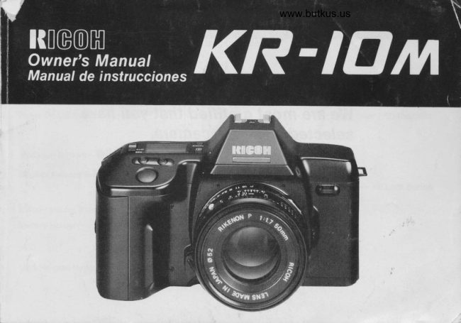
Ricoh KR-10M User manual
User manual for Ricoh KR-10M. 50 pages in English. Read the original PDF, download or print a copy without registration.
50 pagesEnglish3.4 MB PDF
Loading your manual…Open PDF directly
Document details
- Brand
- Ricoh
- Model / document
- Ricoh KR-10M
- Document type
- User manual
- Language
- English
- Pages
- 50
- File size
- 3.4 MB
- Category
- Film cameras
- Document date
- Not specified in catalog
Search available document text
Find a term, then jump to its page in the original PDF. Image-only pages may not be searchable; check the PDF for exact wording and diagrams.
Page 2 · Read text
'f         #I?ffi*


         We are most gratilied that You have
             selected a RICOH camerc.
             Belore using your camera, Please
          be sure to read these instructions
                caref ully.


\
View original page 2Page 4 · Read text
Venmo @mike-butkus-camera  Ph. 2083
PayPal Name  Lynn@butkus.org      www.PayPal.me/lynnbutkus
View original page 4
Page 8 · Read text
www.butkus.us
          1. ATTACHING THE STRAP
          1. Remove the Battery Holder by turning the Battery Holder
             Screw counterclockwise with a coin. (Fig. 1)


          2. Slip the Viewfinder Cap on to the strap. (Fig.2)
                Slip Cap over Viewfinder. (Fig. 3)
               Adjust strap so that  it extends about 25 cm (10 inches)  f rom
               Viewf inder.


Fig.2


Fig. 3
View original page 8Page 9 · Read text
3. Run the strap down through the Upper Strap Lug until  it pro-
                trudes about 8 cm (3 inches) from the lug. Then feed the end
               through the Buckle. (Fig. 4.A.)
                4. Remove Viewfinder Cap off camer4 straighten out strap and
               attach other end to Lower Lug in a similar manner.
                  5.  Adjust the strap length as desired.

Fig. 4-A
                6.  In caseof using both top Lugs, you may be instructed how
                 to fit the strap. (Fig. 4-8.)


Fig. 4-B
View original page 9Page 10 · Read text
www.butkus.us
            2. INSERTING BATTERIES
                 1.  Insert four  f resh AA batteries into the Battery Holder,  f irst
                                                                         u p cor-              checking that  t he + and - on each battery are lined
                 rectly according to the polarity diagram inside the Battery
               Holder. (Fig. 5)

Fig. 5
              2.  Secure the Battery Holder to the camera body by turning
              the Battery Holder Screw clockwise with a coin. (Fig. 6)
              3.  Condition of batteries should be monitored frequently.
            See Section 5 for details.


Fig. 6
           Battery Choices:
         *  Four Penlight (AA) manganese batteries, alkaline batteries
               or nickel cadmium batteries. (We recommend Alkaline bat-
                 teries.)
View original page 10Page 11 · Read text
3. MOUNTING AND REMOVING THE LENS
                                            1.  Pull off the Back Lens Cap to remove it from the lens.(Fig. 4
@mFig. 7
                              2.'Pull off the Camera Body Cap. (Fig, 8)


                        Fig. 8
                         3. Align the red dot o n the camera with  t he red dot on the le ns
                           and mount the lens on the camera. (Fig, 9)
View original page 11Page 12 · Read text
www.butkus.us
us\                  4. Turnclickstheintolensplace.in the(Fig.direction10)    shown by the arrow until  itq)o


                     Fig. 10
                                       5.  To remove the lens, depress Lens Release Button, then turn
                              the lens in the direction shown by the arrow. (Fig. 11)6-\-coP fl
                            Conventional K mount lenses can be used in Aperture-
                                     priority and Manual Modes. Set F-stop number on the lens
                               to "P'l the minimum lens aperture will be given.
                               For best results, use Ricoh original equipment lens. Proper
                           performance of camera may not always be assured with
                    Fig. 11         other lenses.


                                                                                                                     11
View original page 12Page 13 · Read text
4. POWER ON/OFF SWITCH
                             1. Slide the Power On/Off Switch to ON. (Fig- 12)
                          * The camera is designed to shut off the main power supply
                                      automatically to Save battery energy when the camera is not
                                         in use for about 30 secs. even  if the Power On/Off Switch
                                            is left ON. This willturn off the top LCD Display, but the in-
                                  formation contained in camera memory will be retained.
                         Fig. 12                                         Lightly press the Shutter Release Button to turn on the pow-
                                      er and update the LCD Diqplay. For maximum battery life,
                                 always turn the Power On/Off Switch to the OFF position
                           when the camera is stored.


12
View original page 13Page 14 · Read text
www.butkus.us
          5. MONITORING CONDITION OF BATTERIES
           1. Batteries are in good condition when theesymbol ap-
               pears on the top LCD Display Panel. (Fig. 13)


 Fig. 13
          2. When the batteries are nearly exhausted, the:symbol
                 will be displayed on top LCD. (Fig. 14)
              Replace with fresh batteries.


Fig. 14
          3. When the batteries are virtually dead, thecsymbol will
              appear in the LCD Display Panel. Replace with new batter-
                  ies. (Fig. 15)


Fig. 15
                                                                         13
View original page 14Page 15 · Read text
lf the-  symbol lights for about one minute, then disap-
                                  pears, the battery is only capable of retaining camera
                              memory. However, do not remove old batteries until you are
                                 ready to replace them with fresh ones.
                        The memory of the photography mode and exposure
                               counter number will be retained for about 30 minutes
                                   without batteries.  lf you replace with new batteries within
                                      that 30 minutes, the display of the photography mode left
                                      in the camera memory will again appear in LCD Display
                                      Panel.
                                                                                                                                                                                                                                            f reez-                                 Cold temperatures will reduce battery efficiency. In
                                        ing weather, the symbol may turn off and only the :    sym-
                                    bol may show on the LCD Display Panel. lf you are taking
                                    pictures in cold weather, keep the batteries warm and in-
                                        sert them just before shooting.  (lf batteries are removed for
                              more than 30 minutes, counter may reset to "0'1 Film will
                                   automatically advance 3 frames when batteries are rein-
                                        serted.)


14
View original page 15Page 16 · Read text
www.butkus.us
         6. LOADING THE FILM
          Always avoid direct sunlight when loading the  f ilm.
          1. Depress the Back Cover Lock Release Button and slide the
             Back Cover Latch down. (Fig. 16)


Fig. 16
          2. Load the Film Cassette into the Film Chamberand  pull out
             enough film leader to extend just beyond the green mark,
              against the Take-up Spool. (Fig. 17)


Fig. 17
         3. Make sure that the film is within the Film Guides, and that
              the upper sprocket edge is under the Gu ide Plate. (Fig. 18)


Fig. 18
                                                                         15
View original page 16Page 17 · Read text
4. Close the Back Cover so that the Back Cover Latch snaps
                                     shut. (Fig. 19)
                             The  f ilm will now automatically advance until number "1"
                                 appears on the top LCD Display Panel. (Fig. 20)
                            5. As soon as you close the Back Cover, the LCD Display Panel
                                         will show the following signs (Fig, 21):
              O Battery Indicator
             @ Shutter SPEED
            @ Exposure Counter
                                Film advance symbols (these symbols will flash in se- @     E5!:,      @                               quence toward the right to tell you the film is winding)

                                                                                            (lf activated.)  OJ       @@ FilmMultipleCassetteExposureloadedModesymbol
              C Continuous Photography Mode  (lf activated.)
                      Fig.20

    -,r'd.E'dil
       frfr

                            Fig. 21
16
View original page 17Page 18 · Read text
www.butkus.us
            LcD display data can be verif ied by checking the informa-
                 tion visible through Film Loaded Window on camera back.
               (Fis.22l
                 6.   lf the film has not advanced correcily orwas not taken up
               onto the Film Take-up Spool, the Film cassette loaded sym-
                bol will blink until the film has been loaded correcily. Reload
              the film by repeating steps 1-5 shown above.
Fig.22                 lf Non-DX films are loaded in the camera, no LCD warnings
                will be observed. (The film lso speeds must also be set
               manually. See next section.)


                                                                               17
View original page 18Page 19 · Read text
7. SETTING THE FILM ISO SPEED
                         DX coded films are provided with black-and-silver patterns cor-
                               responding to  f ilm speed and number of exposure on roll. The
                           camera reads this pattern and automatically sets itself for DX
                                 films with speeds ranging from ISO 25 to 5000. (Fig.23)


                           Fig. 23
                       DX films
                          *  For advanced applications, you may wish raise or lower the
                               ISO speed of a DX coded film. This may be done by using
                                  the Exposure Compensation Adjustment Button. See Sec-
                                     tion 21 tor details.

                          Non-DX films
                            Using Non-DX   f ilm,  f ilm speed will be set ISO 100 automtical-
                                                 ly. lf you want to use otherfilm speed, you can do it by select-
                               ing Exposure Compensation from 150-6 to ISO 1600.
                                                  re                               Exposu                                    +4 +3 +2  +1   0   -1  -2 -3  -4                                                  n                                       pensatio                        Com
                                Film Speed       6   12   25   50  100  200 400 800  600

18
View original page 19Page 20 · Read text
www.butkus.us
8. fNDICATIONS lN VIEWFINDER Fis.24l
                     C Blinking AE Lock Indicator
                   @ Blinking Underexposure Indicator
                    @ Shutter Speed Scale
                   @ Blinking Overexposure Indicator
                  @ Flash Ready Indicator LEDs
                    @ Shutter Speed Indicator
                    O Blinking Exposure Compensation In-
                                                     Indicator


                                          Fig.24


                                                Viewfinder illum ination
                                     An auxiliary light turns on automatically
                                        when finder l.CD is dark and difficult to see.


                                                                                              19
View original page 20Page 21 · Read text
,l                   )           9. HOW TO HOLD YOUR CAMERA
                          Ltr.rl...                f            (FOR SHARPER PICTURES)
            il|ll)\                            1. Lightly put your right-hand foref inger on the Shutter Release
                                 Button while holding the camera body with other  f ingers.
                           2. Make your right arm comfortable, but keep  it as close to your      ,)K)             body as possible.
                            3. Cradle your camera and lens in the palm of your left hand,
                         Fig. 25         holding  it so that the Focusing Ring can be easily turned
                                  with your fingers.
                                   Brace your left elbow against your body and hold the camera                                            \t)            4.
                                    comfortably against your face. Look through the Viewfinder
                                    to compose your picture.
                           *   lt is important to practice correct shooting position to avoid
         (.                           blurred or tilted pictures. (Figs. 25, 26)
                           Fig. 26


20
View original page 21Page 22 · Read text
www.butkus.us
           10. FOCUSING
            Look through the Viewf inder and turn the Focusing Ring until
           you obtain the sharpest possible image. (Figs. 27-4,27-Bl
            1. Split image focusing spot:
-.          Whenclear image,both imagesthe subjectin theissplit-imagein focus.   spot form a single,
Fig.27-A         Microprism foc using collar:
            When the subject loses its shimmering appearance, the
                 subject is in focus.
               Matte screen focusing field:
            When the subject loses its blurred appearance, the subject
                     is in focus.
                Long focal length lenses and/or lenses with small maximum
                 apertures may black-out part of the central focusing aids.
Fig.27-B      When using these lenses, you must rely on the matte screen
                    for accurate focusing.


                                                                                  21
View original page 22Page 23 · Read text
On many lenses, your depth.of.field can be checked in the fol'
                              lowing way:
                           1. Focus the lens on the subiect.
                            2. The main indicator line opposite the lens focusing scale will
                           show the actual distance to the subject.
                            3. A pair (or pairs) of lines alongside the main indicator will
  www.butkus.us               now show the range of subject sharpness on either side of
                         Fig. 28         the subject that will also be in acceptable focus at one or
                              more aperture (F/number) settings.
                                  For example,  if you are using a 50 mm normal lens, set to
                                         f/16 and focused to 3.0 m (10 ft.), the two depth'of  'f ield in-
                                    dicators (for f/16) will show a range of sharp focus from
                                  about 1.8 m (6 ft.) to 7.6 m (25 ft.). Subjects within this range
                                         will be in good focus. (Fig. 28)


22
View original page 23Page 24 · Read text
www.butkus.us
           11. INFRARED MARK
           Always re-adjust your focus to the infrared focusing mark when
           using infrared films and an R60 (or equivalent)  filter. This is
           necessary because the image forming, invisible lR rays have
           longerwave lengths than the visible light rays you see and fo-
          cus with, and the camera lens focuses them slightly  f urther
           back inside the camera. Therefore, visual focusing can not beFig. 29
            accurate without some compensatio  n.
           1. Attach the R60  f ilter and visually focus on the subject. Read
              the indicated distance off the lens barrel. (Fig. 29)
          2. Shift that distance setting over to the red infrared index
               mark. (Fig. 30)
            Many lenses do not provide separate lR indicator, in which
            case some "Bracketing" of distance settings may be
               necessary.Fig. 30                3.  Set the exposure in accordance with operating instructions
                  for the  f ilm.
              Always refer to film instructions for special precautions and
               procedures when any inf rared  f ilm is used.


                                                                    23
View original page 24Page 25 · Read text
12. REWINDING THE FILM
                       1. DX coded   f ilms will rewind automatically when you reachw                    the end of the roll.I o*Jl          *  Film rewinding is indicated by a series of three dashes flash-
                               ing in sequence  f rom right to left, while the Exposure coun-
                                  ter is counting down. (Fig. 31)tw  o#-tlI
Iw  os'';lI   t@
I ofJl   t@I o*;l
                  Fig. 31
View original page 25Related documents and language editions
From the M. Butkus archive. Original publisher and archive notices are retained.
Check the model and edition against your equipment.
PDF verified 2026-10-10.