Camera accessories
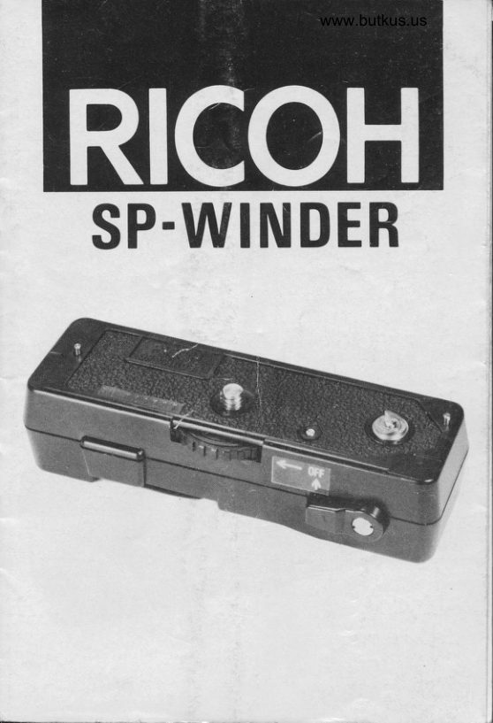
RICOH SP-WINDER - - Direct User manual
User manual for RICOH SP-WINDER - - Direct. 24 pages in English. Read the original PDF, download or print a copy without registration.
24 pagesEnglish1.9 MB PDF
Loading your manual…Open PDF directly
Document details
- Brand
- Ricoh
- Model / document
- RICOH SP-WINDER - - Direct
- Document type
- User manual
- Language
- English
- Pages
- 24
- File size
- 1.9 MB
- Category
- Camera accessories
- Document date
- Not specified in catalog
Search available document text
Find a term, then jump to its page in the original PDF. Image-only pages may not be searchable; check the PDF for exact wording and diagrams.
Page 4 · Read text
Digitally signed by Mike Butkus
                                                DN: cn=Mike Butkus, o=Butkus camera manuals,
                                                     ou=butkus.org, email=mike@butkus.org, c=USMike Butkus   Date: 2024.03.04 01:08:40 -05'00'
View original page 4Page 5 · Read text
www.butkus.us

PARTS
 1. Positioning Pin
 2. Attachment Knob
 3. ON/OFF Switch
 4. Film Advance Coupler
 5. Film Rewind Release Button
 6. Wind Crank Compaftment
 7. Tripod Socket
 8. Wind Crank
View original page 5
Page 6 · Read text
ATTACHTNG THE WTNDER
  1. Turn the Attachment Knob Ql in the opposite direc-                riI
     tion to the arrow. As the screw engages in the tripod                                                                                     ,d
     socket, check that the Positioning Pins (1 ) are cor-
    rectly inserted in the camera's positioning pin
    pockets. Then tighten the Attachment Knob to lock
     into position. (Fig. 1)

TENSIONING THE SPRING MOTOR
  1. Pull out the Wind Crank (8) and turn it in the direc-
     tion of the arrow until it stops. (Fig. 2)
 2. When the Spring Motor is fully wound, put the Wind
    Crank back into position. (Fig. 3)
  *   lf the film has not beerr advanced one frame, or if the
    Film Advance Coupler is not engaged, the Spring
    Motor will start operating as soon as the Wind Crank
     is put back in position.
       It will continue to operate until the film is advanced
    or the Film Advance Coupler engages.

SH OOTI NG
 1. Push the ON/OFF Switch (3) down until the red
   mark is visible. (Fig. a)
 2. Set the aperture, distance and shutter speed accor-
    ding to the instruction booklet with the camera,
 3. Press the shutter release button and shoot.

                    -2-
View original page 6Page 7 · Read text
www.butkus.us

 4. When you release the shutter release button, the
   Winder will advance the film by one frame.
 * Approximately 1O frames can be advanced with
   each full tension of the Winder.
REWINDING THE FILM
 1. Push the Film Rewind Release Button (5) under the
    Winder upwards with your finger. When you release
    the button, it will return to its former position, but the
    film rewind release button on the camera will stay
    locked in position. (Fig 5)
 2. Pull up the film rewind crank on the camera and turn
      it in the direction of the arrow to rewind the film.
     (Fig. 6)
  *  lf the film ends midway through a frame, the Film
    Rewind Release Button may not stay locked in posi-
    tion. In this case, keep the Film Rewind Release
    Button pressed with your finger as you rewind the
      film.

DETACHING THE WINDER
  1. Push the ON/OFF Switch up until the red mark is
    covered. (Fig. 7)
  2. Turn the Attachment Knob on the Winder in the
     direction of the arrow and remove. (Fig. 8)
  *   lf you have the winder unattached from the camera,
    with the switch on. and the wind crank is in the com-
    partment, the spring motor will unwind.
                    -3-
View original page 7Page 8 · Read text
* Repeated operation of the Winder's ON/Of f switch,
   when the camera is not being used, will cause the
    spring motor to gradually discharge.

MAI NTENANCE
    After use, gently wipe the dirt and dust off with a soft
     cloth.
        lf the Winder is not going to be used for a while, set
    the ON/OFF Switch to ON to discharge the Winder.
    then keep it in the OFF position.
   Do not leave the Winder in high temperature or
    humidity.
   Any sudden change of temperature will cause con-
    densation to form inside the Winder.
View original page 8Page 9 · Read text
www.butkus.us


     SPECIFICATIONS
        Applicable cameras:
          RICOH sOOME, sOORF, 5OOST, sOOZF
        Drive system:
            Spring motor
r     Number of frames advanced:
            Approximately 1O frames when fully wound
'       Exposure counter:          With exposure counter on the camera
       Rewind system:
           Manual rewind by camera's rewind lever
       Tensioning the spring-winder:
          By turning the wind-crank (20 times)
I        rvrount:
            Attached via the camera's tripod socket
        Tripod socket:
           Underneath the winder
        Dimensions:
                1 14 mm (width) x 29 mm (height) x 36 mm (depth)
             4.5" x1.1" x1.4"
       Weight:
                            oz)rt-I          15bg (5.5


                           -5-
View original page 9Page 10 · Read text
PIECES DETACHEES
  1. Broche de mise en place
 2. Bouton de fixation
 3. Commutateur ON/OFF
 4. Accouplement d'avance du film
 5. Bouton de d6brayage
 6. Logement de manilvelle de bobinage
 7. Pas femelle du tripied
 8. Manivelle de bobinage
View original page 10
Page 11 · Read text
www.butkus.us

FIXATION DU MOTEUR
  1. Tourner le bouton de fixation (2) dans le sens oppos6
   de la fldche. Tandis que la vis s'engage dans le pas
    femelle pour tripied, v6rifier si les broches de mise en
    place (1 ) sont correctement ins6rees dans les pas fe-
     melles.
    Ensuite serrer le bouton de fixation pour fixer en
    place. (Fig. 1)
TENSTON DU MOTEUR A RESSORT
  1. Extraire la manivelle de bobinage (8) et la tourner
    dans le sens de la fldche jusqu'd ce qu'elle s'arr6te.
     (Fis. 2)
 2. Ouand le moteur d ressort est bobin6 d fond, re-
    mettre la manivelle de bobinage en place. (Fig. 3)
  *  Si le film n'a pas 6t6 avanc6 d'une image. ou si l'ac-
    couplement d'avance du film n'est pas engag6, le
    moteur d ressort commencera d fonctionner dds que
     la manivelle de bobinage sera remise en sa place.  ll
    continuera d fonctionner jusqu'd l'avance du film ou
    jusq'd ce que l'accouplement d'avance du film soit
    engag6.

PRISE DE VUE
  1. Appuyer sur le commutateur ON/OFF (3) jusqu'd ce
    que le repdre rouge soit visible. (Fig. 4)

                        -8-
                                                                                                                                                                                                                                                                                                                                                                                                        I:I
                                                                                      -laJ
View original page 11Page 12 · Read text
2.  R6gler l'ouverture, la distance et la vitesse d'obtura-
    tion suivant le mode d'emploi fournit avec votre ap-
     pareil.
  3. Appuyer sur le bouton de d6clenchement de l'obtu-
    rateur et effectuer la prise de vue.
 4.  Lors du d6clenchement du bouton de d6clenchement
   de l'obturateur, le moteur avancera le film d'une
    image.
 *  Environ 1O images peuvent 6tre avanc6es avec cha-
   que tension compldte du moteur.
REMBOBINAGE DU FILM
 1. Pousser le bouton de d6brayage du film (5) qui se
    trouve sous le moteur vers le haut avec le doigt.
   En rel6chant le bouton,  il retournera en sa position
      initiale, tandis que le bouton de d6brayage restera
     v6rouill6 en place. (Fig. 5)                                         sl
 2. Extraire la manivelle de rembobinage de film et la
    tourner dans le sens de la fldche pour rembobiner le
     film. (Fig. 6)
 *  Si le film s'arr6te au milieu d'une image, le bouton de
    d6brayage risque de ne pas rester v6roui116 en place.
    Si c'est le cas, manintenez le bouton de d6brayage
    enfonc6 avec votre doigt tandis que vous rembobinez
     le film.


                       -9-
View original page 12Page 13 · Read text
www.butkus.us

DEPOSE DU MOTEUR
  1. Pousser le commutateur ON/OFF jusqu'd ce que le
    repdre rouge soit recouvert. (Fig. 7l
 2. Tourner le bouton de fixation qui est sur le moteur
    dans le sens de la fldche et d6poser le moteur. (Fig.
     8)
 *  Si le moteur reste fix6 d l'appareil, avec le commuta-
     teur sur ON, et la manivelle de bobinage dans son lo-                                                                                                                       t    gement, le moteur d ressort se d6bobinera.
 *  L'op6ration r6pdt6e du commutateur ON/OFF du
    moteur, quand l'appareil n'est pas utilis6, causera  la
    d6charge graduelle du moteur d ressort.

ENTR ETI EN
 o Aprds utilisation, essuyer doucement les salet6s et la
    poussidre avec un chiffon doux.
 o Si le moteur ne doit pas 6tre utilis6 pendant un cer-
    tain temps, r6gler le commutateur ON/Off sur ON
    pour d6charger le moteur, puis le laisser en position
    OFF.
 o Ne pas laisser le moteur en des endroits humides ou
    soumis d une haute temp6rature.
 o Tout changement brusque de temp6rature entrainera
   une formation de vapeur d l'int6rieur du moteur.


                   -10-
                                                                           ,J.
View original page 13Page 14 · Read text
SPECIF ICATIONS
Applicable aux appareils:
   RrcoH 500ME, 500RF, 500sT, 5002F
Systime d'entrainement:
    Moteur d ressort
Nombre d'avance d'images:
    Environ 1O images quand bobin6 d fond
Posemitre:
    Posemdtre sur l'appareil
Systdme de rebobinage:                                               '
    Rebobinage manuel avec levier de rebobinage de
     l'appareil
Tension du moteur d ressort:
   En tournant la manivelle de bobinage (20 fois)
Montage:
     Fixation par pas femelle du tripied
Pas femelle du tripied:
   En dessous du moteur
Dimensions:
   114 mm (largeur) x 29 mm (hauteur) x 36 mm
     (profondeur)
Poids:
   155 gr.
View original page 14Page 15 · Read text
www.butkus.us


                                  .T'..   TEILE
        1. Positionsstift
       2. Befestigungsknopf
       3. Schalter ON/OFF
       4. Filmtransportkuppler
            Filmruckspulentriegelungsknopft       5.
        6. Aufzugskurbelgehduse
I       7. StativanschluB
        8. Aufzugskurbel


                                - 13 -
View original page 15Page 16 · Read text
ANBRINGEN DES MOTORANTRIEBS
  1. Den Befestigungsknopf (2) entgegen der Pfeilrich-
    tung drehen. Sobald die Schraube in das Stativge-
    winde eingreift. mu8 tiberpruft werden, ob die Posi-
     tionsstifte (1) richtig in die Positionsstiftbuchsen  der
    Kamera eingefi.ihrt sind. Danach die Befestigungs-
    schraube zum Befestigen des Motorantriebs festzie-
    hen. (Fig. 1)

AUFZIEHEN DES FEDERMOTORS
  1. Die Aufzugskurbel (8) herausklappen und Uis zum
    Anschlag in Pfeilrichtung drehen. (Fig. 2)
 2. Wenn der Federmotor vollstiindig aufgezogen ist, die
    Aufzugskurbel wieder in seine Ausgangsstellung
     zurrickklappen.  (Fig. 3)
  *  Falls der Film nicht um ein Bild weiter transportiert
   wurde bzw. der Filmtransportkuppler nicht im Ein-
      griff ist, beginnt sich der Federmotor abzulaufen, so-
    bald die Aufzugskurbel wieder in seine Ausgangs-
    stellung zurtickgeklappt wurde. Der Federmotor
     lSuft solange ab, bis der Film transportiert wurde
    bzw. der Filmtransportkuppler eingreift.


                                                                                                                                                                                            \FOTOGRAFIEREN
 1. Den Schalter ON/OFF (3) hinunterdrtlcken. bis die
    rote Markierung sichtbar wird. (Fig. 4)


                                                                                                                                                                   I
                     -14-
                                                                                                                                                                                                                                                                 II
View original page 16Page 17 · Read text
www.butkus.us

           2. Blende, Entfernung und VerschluBzeit gemdB Kame-
                    ra- Bedienu ngsanleitu ng einstellen.
           3. Den Ausloseknopf drricken und eine Aufnahme ma-
                chen.
           4. Sobald der Ausloseknopf losgelassen wird, transpor-
                  tiert der Federmotor den Film um ein Bild Weiter.
           *  Mit voll aufgezogenem Federmotor konnen ungefdhr
           10 Bilder transportiert werden.
     ZURUCTSPULEN DES FILMES
            1. Den Filmruckspulentriegelungsknopf (5) unter dem
             Federmotor mit dem Finger nach oben driicken.
         Wenn der Entriegelungsknopf  losgelassen wird,
               kehrt er in seine Ausgangsstellung  zur0ck. wobei der
IItl               Filmrrlckspulentriegelungsknopf an der Kamera je-
                I
            doch eingerastet bleibt. (Fig. 5)
           2. Die Filmrrickspulkurbel an der Kamera herausklap-
     t            .  pen und in Pfeilrichtung drehen, um den Film zurrick-
              zuspulen. (Fig. 6)


      1           *  Falls der Film wdhrend des Zurtickspulens stehen
                  bleibt, konnte die Ursache auf den nicht mehr einge-
            rasteten Filmruckspulentriegelungsknopf   zurtick-

          I

                 I                  I            zufuhren sein.
               In diesem Fall den Filmrrickspulentriegelungsknopf

                  I
            wdhrend dem Zurrickspulen mit dem Finger nieder-
              gedruckt halten.

                 l

                                   - 15 -
View original page 17Page 18 · Read text
I
                                                                                                                                                                                                               I


ENTFERNEN DES MOTORANTRIEBS
  1. Den Schalter ON/OFF nach oben drticken. so daB die
    rote Markierung zugedeckt wird. (Fig. n
 2. Den Befestigungsknopf am Motorantrieb in Pfeilrich-
    tung drehen und entfernen. (Fig. 8)
 * Wenn der Motorantrieb mit eingeschaltetem Schal-
     ter und mit zuruckgeklappter Aufzugskurbel von der
    Kamera getrennt ist, l6uft der Federmotor ab.
 * Wenn der Schalter ON/OFF am Motorantrieb wiede-
     rholt betdtigt wird, wobei die Kamera jedoch nicht
    gebraucht wird, bewirkt dies ein allmdhliches Ent-
    spannen des Federmotors.

PFLEG E
 o Nach der Benutzung sind Schmutz und Staub mit ei-
   nem weichen Lappen abzuwischen.
 o  Falls der Motorantrieb fur eine Weile nicht mehr ver-
    wendet wird, sollte der Schalter ON/OFF zum Ent-
    spannen des Federmotors zuerst auf ON und danach
    auf OFF gestellt werden.
   Den Motorantrieb keinen hohen Temperaturen bzw.
    keiner ribermdBigen Feuchtigkeit aussetzen.
     Plotzlicher Temperaturwechsel verursacht Konden-
    sation im Innern des Motrantriebs.
View original page 18Page 19 · Read text
www.butkus.us

TECHNISCHE DATEN
Verwendbare Kameras:
   RICJH 5OOME, 5OORF, 5OOST, sOOZF
Antriebssystem:
    Federmotor
Anzahl der transportierten Bitder:
    Ungefdhr 10 Bilder bei voll aufgezogenem Federmo-
     tor
Bildzdhlung:
    Mit Hilfe des Bildzdhlwerks der Kamera
 Filmrilckspulung:
    Manuelles Ruckspulen mittels Ruckspulkurbel der
    Kamera
Aufziehen des Federmotors:
    Durch Drehen der Aufzugskurbel (20 Umdrehungen)
 Befestigung:
   Am Stativgewinde der Kamera befestigt
StativanschluB:
    Unter dem Federaufzug
Abmessungen:
    114 (B) x 29 (H)x 36 (T) mm
 Gewicht:
       1 55g
View original page 19Page 20 · Read text
PIEZAS
 1. Pasador de colocaci6n
 2. Perilla de sujeci6n
 3. Interruptor de encendido/apagado
 4. Acoplador para avance de pelicula
 5. Boton para soltar el rebobinador de pelicula
 6. Compartimiento de la manivela de rebobinar
 7. Rosca para tripode
 8. Manivela de rebobinar
View original page 20
Page 21 · Read text
www.butkus.us

INSTALACION DEL REBOBINADOR
  1. Gire de la perilla de sujeci6n (2t.en direcci6n opuesta
   a la flecha. Cuando el tornillo entra en la rosca para
     tripode, confirme que los pasadores de colocaci6n
      (1 ) est6n insertados correctamente en los
     recept6culos correspondientes de la cdmara. Luego,
     apriete la perilla de sujeci6n para que el rebobinador
    quede bien apretado en su posici6n.
TENSADO DEL MOTOR A RESORTE
  1. Tire de la manivela de rebobinar (8) y girela en la
     direcci6n de la flecha hasta que se detenga. (Fig. 2)
 2. Cuando el motor a resorte est6 totalmente
     enrrollado. ponga la manivela de rebobinar otra vez
   en su posici6n. (Fig. 3)
  * Si la pelicula ha avanzado un cuadro, o si el
    acoplador de avance de pelicula no est6 acoplado. el
    motor a resorte comenzarS a operar tan pronto como
     la manivela de rebobinar quede puesta otra vez en su
    posici6n original.
    Continuar5 operando hasta que la pelicula quede
    avanzada o hasta que se acople el acoplador de
    avance de pelicula.

D ISPAR O
  1. Baje el interruptor de encendido/apagado hasta que
   quede visible la marca roja. (Fig.      )
View original page 21Page 22 · Read text
la 2. Coloque la apertura. ajuste la distancia y fije
    velocidad de disparo de acuerdo a las instrucciones
   que acompafian a la cSmara.
 3. Presione el bot6n del obturador y tome la foto.
 4. Cuando suelte el bot6n del obturador, el rebobinador
    autom5tico avanzar5 la pelicula un cuadro.
 * Con el resorte del rebobinador completamente ten-
   sado se pueden avanzar hasta 1O cuadros aprox-
    imadamente.
BOBINADO DE LA PELICULA
  1. Empuje hacia arriba el bot6n que suelta el
    rebobinador de pelicula (5) que estS debajo del
    rebobinador. Cuando suelte el bot6n, regresar5 solo
   a su posici6n anterior. pero el bot6n de soltar el
    bobinador de pelicula de la cSmara seguird fijo en su
    posici6n. (Fig.5)
 2. Tire de la manivela de rebobinar la pelicula de la
    c5maray girela en la direccion de la flecha para
    bobinar la pelicula. (Fig. 6)
  * Si la pelicula se detiene a la mitad de un cuadro,
    puede ser que se deba a que el bot6n de soltar el
                                                       su    rebobinador de pelicula no est6 bien fijo en
     posici6n.
    En este caso, mantenga este bot6n apretado con el
    dedo mientras bobina la Pelicula.
View original page 22Page 23 · Read text
www.butkus.us

PARA SACAR EL REBOBINADOR
  1. Empuje hacia arriba el interruptor de encendido/
    apagado hasta que desaparezca la marca roja. (Fig. 7)
 2. Gire la perilla de sujeci6n del rebobinador en la direc-
    ci6n de la flecha y sepSrelo. (Fig. 8)
 * Si Ud. tiene el rebobinador separado de la cdmara
    pero con el interruptor de encendido prendido y la
    manivela de rebobinado est5 en el compartimiento,
    se desenrollard el resorte del motor del rebobinador.
 *  Repetir la operaci6n de encendido/apagado del in-
    terruptor de encendido/apagado cuando no use la
   cSmara, har5 que el motor a resorte se vaya
    descargando gradual mente.

MANTEN IM IENTO
 o Despu6s de usarlo, limpie quitando la suciedad y el
    polvo de la unidad usando un pafio suave.
    Si no piensa usar el rebobinador por cierto tiempo,
   deje ef interruptor de encendido /apagado en
    posici6n de prendido para descargar el motor a
     resorte del rebobinador y luego d6jelo en posici6n de
    apagado.
  No deje el rebobinador en lugares de mucha
    temperatura o humedad.
   Tenga en cuenta que cualquier cambio sibito de
    temperatura puede hacer que se condense el agua  ,
   de humedad dentro del rebobinador, cosa con-
    traproducente para la unidad.
                   -22-
View original page 23Related documents and language editions
From the M. Butkus archive. Original publisher and archive notices are retained.
Check the model and edition against your equipment.
PDF verified 2026-10-10.