Sewing machine accessories
Singer 66-16 — User manual
User manual for Singer 66-16. 76 pages in English. Read the original PDF, download or print a copy without registration.
76 pagesEnglish6.0 MB PDF

Loading your manual…Open PDF directly
Document details
- Brand
- Singer
- Model / document
- Singer 66-16
- Document type
- User manual
- Language
- English
- Pages
- 76
- File size
- 6.0 MB
- Category
- Sewing machine accessories
- Document date
- Not specified in catalog
Search available document text
Find a term, then jump to its page in the original PDF. Image-only pages may not be searchable; check the PDF for exact wording and diagrams.
Page 1 · Read text
$


 INSTRUCTIONS FOR USING
   SINGER
 ELECTRIC SEWING MACHINE
    Model 66-16


THE SINGER MANUFACTURING COMPANY
View original page 1Page 3 · Read text
SEWING MACHINE         66-16
The SINGER 66—16 is another in a long Iinc of products
resulting from the skill and ability of SlNCER craftsmen.

      Copyright, u. 5.111. 1940, 1947, 19411, 1950, 1951, 1953 and 1954
                 by The Singer Manufacturing Company
                  A" Rich" Reserved lor all Covnniet
‘A Trade Mark  01 THE SINGER MANUFACTURING COMPANY
View original page 3Page 4 · Read text
AS THE OWNER OF THIS
SINGER SEWING MACHINE:

You have a machine made with the same care
and craftsmanship that have been the hallmark
of SINGER products for more than a century,
We  are  acutely aware that SINGER Scwin
Machines havc become an American tradition
and arc intcnScly proud of, and dctcrmincd to
continue, this hcritagc.
Your SlXGER  "66"   is  the  product  of  this
pride, dctcrminntinn and the unsurpassed tech-
nical  skill of SINGER,  This smooth-running
machine, comlwincd with your own  skill, will
luring you a new world of sewing enjoyment.
lixtlusivc drcsscs for yourself, clothing for your
family and a multitudc of items for  ’our homc
will he nun-s   All at  u lrnctinn of  t  cit rcady-
mmlc cost.
View original page 4
Page 5 · Read text
WHAT SlNGER SERVICE MEANS TO YOU

Over 1400 SINGER SEWING LENTERS in (he
Unircd States alonc scnc womcn “ho SC“
IN'STRU(TION by skiIIL-d tL'uL‘hL-rsIS an Ln to
purL‘hnscrs  of ncw SINGER SE“ ING  \I\-
CHINES at no L-xtra charge. Budget courscs in
home  dressmaking,   hoinc   dccriration  and
Fashion Stitching are also nvuiInhILz
REPAIR SERVICE  is  as  comL-niL'nt  as your
telephone.  \\ han~\Lr your machinL nchs 1d-
|usuncnt, a (rainLd SIN‘GER rcprcswrltIVC u ill
ml]  at )0ur homL. SINGER'  Service assures
cxccllcnt workmanship, gunmmccd rcpairs and
SINGER‘ parts. A wriltcn estimate is giVL-n I’m
your approval.
And rcmcmbcr, your SINGER SEWING (EN-
TER and thc SINGER ScrviL‘c L‘nr arc ILIL'HIIIICLI
by the famous SINGER  RL'LI ”‘S


                                                               3
View original page 5Page 6 · Read text
00...‘.....I........


                                     Before Inserting Electric Plug
                                           be sure voltage and number of cycles
                                       stamped on motor nameplate are within
The SINGER‘ Electric Motor          the range marked on the electric meter
is located at the back of the machine and     installed by the electric power company.
can be operated on either alternating or
direct current. The standard windings of
the motor are for 110-120  volts, and   To Connect the Machine to
                                           Electric Service Linemotors can be furnished for any voltage
between 95 and 250. Special motors can    Push three-pin terminal plug on three-
be furnished for 32 volts direct current,     pin terminal block at right of machine
and for 50 volts alternating or direct    and connect plug at other end ofcord to
current.                                     nearest electric outlet.
View original page 6Page 7 · Read text
The light  is turned "on" or "off" by
turning switch A, Fig. 2 to the right.
To Remove the Bulb
Grasp light socket so that thumb ex—                                                                        Fig. 2. Tb- L155:
tends over switch A. Prcss shadc with
thumb  at B  to  release  it from two   To Replace the Bulb
catches and  slide  it  halfway out  of     Press ncw bulb into socket with bulb
shade bolder D. Do not attempt to     pin C, Fig. 2 cntcring slot of socket and
unscrew bulb. Press it into sockct and     turn  it over towar   the machinc  in
at same time turn bulb ovcr from the     direction shown in Fig. 28 to lock bulb
machine in direction shown in Fig. 28     pin in position. Return shade to posi-
to unlock bulb pin C.  Fig.  2, then     tion shown in Fig. 2.
withdraw bulb.
                                            teens Ff?—           r??— fl      ...__/ 3mF         I
                                        UNLOCKS   ..-     ‘—'
                     Fig. 2A                                                   Fig, 23
View original page 7Page 9 · Read text
eta-l-100000tobnuoe


;iiimanna intern


 Raise needle to its highest point. Draw   TO WIND THE BOBBIN
 the slide in bed of machine to the  left
                                    To stop motion of needle, hold hand and  press down on  bobbin  ciector J.                                        wheel K,  Fig. 4 and  loosen knurled Fig.  3. This will raise bobbin so that
                                          scrcw L by turning it toward you.  it can be easily removed from bobbin
 case.                                         Place bobbin on bobbin winder spindle,
                                                as shown  in Fig.  5, as far  it will go.
                                                 Prcss bobbin winder against hand wheel
                                                  until latch N, Fig.  5 drops down and
                                            holds bobbin winder pulley P against
                                             the hub of the hand whccl.
                                              Place spool of thread on spool pin.
                                         Lead thread through guide  1 on arm of
                                          machine, and into the lower notch of
                                          bobbin winder thread guide 2  at  the
                                         from of machine bed.
             Fig.  3. Rut/wing flu Bobbin
View original page 9Page 10 · Read text
Pass thread back of guide 2 and into its
                                 upper notch. and through hole M, Fig.
                                          5.  in  lcft  side  of bobbin  5 from  (he
                                         inside.

                               Hold cml ol thrcad and prcss controller
                                         as  for sawing. The cnd  oi the thread
                                must be held until  it brcaks off. Fig. 5
                              shows bobbin winder  in  position  for
                                 winding.
                              Allow guide 2 to control flow of thread
                                      so that  it winds on bobbin  in uniform
                                         lcvul rows.
                           When bobbin is filled, tlk’ bobbin windcrMy, 4  Mar/rim  I/|rz'.1.tt'./ for
    H jut/mg the Bab/1m                           is automatically released.
View original page 10Page 11 · Read text
RL-inow bobbin  lrom  spindlc and  rc
rightL-n knurlL-d scrL-w  L. Fig. 4.
II thrL-aLl  LloL-s not winLl L~vcnly on bob
bin,  loosm   thL'  screw  whiL‘h  hold;
bobbin windcr thrcad guidc  1, Fig. 4
on bed ol machinc. Turn this guide to
(hL‘  left  if bobbin winds high on th
right  Turn  guide  to  right   il  bobbin
winds high on  thL-  Iclt   \\'hL-n guidL-  is
proerly   L‘L-ntcrL'd.  thruad  will  Wind
cvunly  across  bobbin.  ThL-n   tightL-n
(hrL-aLl  guiLlL' scrcw.
 ll prL-smrL- of bobbin windcr pulley  P.
Fig.  5  auainsr hub of hand whccl  is
insulIiL'iL-nr  for winding  bobbin,  prus~
down on bobbin winLlLr until latch N
drops and  looscn  adiustinu erL'w Q.
Thcn press pulley P hrmly against hand
th-Ll and  prL-ss down  latch N whilc          Mg.  5. flab/mt H'mJL'r ."l[[lllfllit”1’
righrcninp screw Q.
View original page 11
Page 12 · Read text
Hold bobbin between thumb and forc-
fingcr of left hand, the thread leading on
top from  right  to  left,  as shown  in
Fig. 6.


                                                                 Fig. 7‘ Thu/ding r/Jt Babb/u Can

                                             Place bobbin into bobbin case and draw
                                            thread  into slot  1.  Fig.  7  in bobbin
                                                  case, as shown. Draw thread backward
                                       between bobbin case and tension spring
                                                 until  it reaches notch  2. Fig. 8, then
          Fig. 6. Rip/Jung flu Bobbin               pull thread toward the right. as shown
View original page 12Page 13 · Read text
o...l.'l°oou:aaiatatCQoO".'.m'.  to!09r.ee

        in Fig. 8. When closing the slide. see
      that the thread  is in slot  1, Fig. 9  in
      right edge of slide, as shown.


                                                        Hg.  9. l'm/lr T/wudmg Camp/om!
View original page 13Page 14 · Read text
Insert needle with its flat side to the
                                          right up into needle clamp as far as it
                                             will go, then tighten thumb screw H.For perfeCt stitching, thread should be
selected  according  to  fabric  to  be
stitched. Needle must be correcr size for
thread which must pass freely through
eye of needle.
Select correct needle according to chart
on page 6.
Be sure that needle is not blunt or bent.

10 SE? THE NEEDLE
Raise needle bar to its highest position
and loosen thumb screw H, in needle
clamp.                                                        Fag. 10. To Set tin Needle
View original page 14Page 15 · Read text
See Fig. 11
                        Raise take-up  lever  5  to  its highest
                      pomt.
                         Place spool of thread on spool pin
                      Lead thread into thread guide 1
                 Down and from right to left between
                         tension discs 2
                         Into the loop of take-up spring 3
                  Under slack thread regulator 4 (not
                    through  eye  in thread  regulator)
                  Up and from right to left through hole
                          in take-up lever 5
                 Down through guide 6 on face plate
                 Down through lower wire guide 7
                   From  left  to  right  through  eye  of
                         needle 8.
 .-                    -                                                                              -     Draw  about  two  inches  of  thread
"A H. L PP" ”NM,“     through eye of needle.
View original page 15Page 16 · Read text
Hold  end  of needle thread with  left     again and thread take-up lever is at its
hand and turn hand wheel over toward     highest point. Pull up needle thread and
you  until needle moves down and up    bobbin thread will come up with  it, as
                                   shown in Fig. 12.


                                       Lay both threads back under the presser
                                               foot diagonally across the feed, to the
                                               right  or  left, depending upon which
                                                 side of the needle the material  is to be
                                               located. so that when the presser foot is
                                           lowered. the threads will be firmly held
                                        between the feed and the presser foot.


     Fig. 12. Dmu in; Up flu I v'mhr T’wmf
View original page 16Page 17 · Read text
. ..   :;~m.£           1-52...qu


'~                   .  wamsfiifie


     Be sure to have thread take-up lever
         5. Fig. 11  at its highest point.
       Place material beneath presscr foot R.
       turn hand wheel to bring point oI needle
       into material, then loWer presser foot
       by means of presser bar  lifter  S, and
        start  to Sew.  Press controller to start
       machine.  The  speed  depends  upon
      amount of pressure on controller.
      Most materials require only guiding.y for
        best sewing results. However, the miraa
        cle  fabrics  such  as  nylons,  tlacmns,
       orlons,  blends  with  various  rayons,
       pulled weaves, sheets. jerseys and  tri—
        cots, which, by  their  nature,  require
        light pressure, also require support  in
       the form of holding the material taut at

                                                                            l')
View original page 17Page 18 · Read text
0.0.00...000.000.00000QOOCQQCOOOOC‘OOOQ.


     the back and front of the needle as the   BASTING
      needle enters the fabric. This support
      assures a smooth, even seam.            The longest stitch, No. 6 on the stitch
                                                     indicator,   is  satisfactory  for  basting.
     Never pull the material when sewing.      The basting stitches are easily removed
     The machine will sew  its own thread     by clipping every sixth stitch and with-
                                           drawing the long continuous thread.    when sewing from one piece of material
      to another. However, avoid operating    Machine basting  is firmer, more even
     a threaded machine with presser foot up    and much quicker than hand basting.
     and without fabric under the foot.

   TO TURN A CORNER                 I'O SEW BIAS SEAMS
     Stop  machine  when  eye  of  needle    Use a shorter stitch when sewing bias
      reaches material on its upward stroke.     or curved seams to increase the  elas~
     Raise presser foot and. using needle as a      ticity of the seam and to prevent seam
      pivot,  turn material as desired. Then      failure under  pressure. No change  in
     lower presser foot and resume sewing.        tensions is required.
View original page 18Page 19 · Read text
OOOQOOOQO

TO REMOVE THE WORK
Stop machine with thrL-ad iiikc up lcvcr
S. Fig.    I    l  at its hitthL-st point.
Rili\c  prL-sscr loot by  niL-ans oi prcser
bar  liltL'i‘  S. Fig.  I5. draw labric back
and  to  (In  1th  and   sL~\'L'r  thrL-ads on
thruad Luttcr T. Fig. I5.  I’lgiL’L  L-nds of
threads undcr prLser  loot    \\II1L'I] mar
cth  is not  in "bu.  ixiisL' prL-ssL-r toot to
prL-vL-nt  iniur)‘ to prcssur foot and  I'LL-d
U. Fig.  15.

TO REGULATE LENGTH                                    l‘lg. N. Tu  Ri';u.".i'li' Milt/v [nut/Ia
OF STITCH
Th: IillehInL‘ is adiustablc to niakL' from    To L'hzingL lcngth ol stitch, sci lcvch’.
6  to  23 or  mort- stitchcs  per  inch,  as     Fig. M With  it< uppL-r sidu in him with
indiLatLd by [IiL' numL-rals on stitch ind|~     tho  nuincral  rL-prLsL-nting:  rhc  dL-sircd
caitor platL- V, Fig. 14.                     nuinhcr ol stitL'Iics per inch.

                                                  I7
View original page 19Page 20 · Read text
To feed the material toward you, raise    To increase pressure, turn thumb screw
the lever W, Fig. 14 to the up    por—    X,  Fi    .  15 clockwise or downward.
tion of the stitch indicator   ate V,    To lig  ten pressure, mm thumb screw
Fig.  14 marked "Back Taci". The   X so that it screws upward.
machine will then stitch  in a reverse
direcrion, thus making it easy to "back
tack" and to fasten ends of sums.

‘l'O REGULATE PRESSURE
ON PRESS!!! FOOT
For average materials, the pressure of
the presser foot on the material seldom
requires changing. Heavy materials rc-
qurre more   rcssure than light weight
materials. The pressure should be only
heavy enough to prevent side creeping
of material and  still obtain a uni cm            Fig. 15. Tbs/716 Sm far Rogulcmng
length of stitch.                         Pnum on Prmcr Fool
View original page 20
Page 21 · Read text
SCOOOOOOQQOOOOOOQOQCOCOO...000.000.0000

    Thread Tensions
     For  perfect  stitching,  the  tension on
      needle  and  bobbin  threads  must  be
     heavy enough to pull threads to center
      of thickness of material and make  a
     firm  stitch,  as shown  in  Fig.  16.

       If needle thread lics straight along top
      side  of  material,  tension  on  needle
      thread is too heavy or tension on bobbin
      thread is [00 light, as shown in Fig. 17.

       If bobbin thread lies straight along the
      underside of the material,  tension on
      needle thread is too light or tension on
      bobbin thread is too heavy, as shown in
      Fig. 18.                                                         Fig. 18. Impulse! Inkling
View original page 21Page 22 · Read text
To decrease tension, turn thumb nut
                                B gradually to the left (counter-clock~
                                          wise) until the required tension  is ob-
The tension on the needle thread can be     tained. Each lower number  denotes
tested  only when  the  presser  foot  is     less tension.
down.                              The tension indicator G is marked with
The numerals "0" to “9" on dial D.     the signs + and         , which indicate the
Fig.  l9  indicate  different  degrees  of     direction in which to turn thumb nut B
tension that can be obtained. The num—      for more or less tension.
bers do not denote  size of thread  or
ounces of tension.
When the tension has been correctly set.
as described on pages 24 and 25. note
number at indicator line Y. Fig. 19 so
that this setting may be regained should
the tension be altered for special work.
To increase tension, turn the thumb
nut B gradually to the right (clock-                                                              o, ___lwise) until the required tension  is ob-                                                  _,
tained.  Each higher number denotes                 Fig. 19. To Regulars le/a
increased tension.                                          Thread Tom/an
View original page 22Related documents and language editions
SingerPDF
Adjuster's for the Singer Model 20
Service manual
19 pages · EnglishRead →
SingerPDF
Singer 101-4 & 101-12
User manual
56 pages · EnglishRead →
SingerPDF
Singer 101-4 & 101-12 (black and white scan)
User manual
54 pages · EnglishRead →
SingerPDF
Singer 115
User manual
36 pages · EnglishRead →
SingerPDF
Singer 127 & 128
User manual
18 pages · EnglishRead →
SingerPDF
Singer 12K
User manual
12 pages · EnglishRead →
SingerPDF
Singer 15
User manual
36 pages · EnglishRead →

SingerPDF
Singer 15-125
User manual
38 pages · EnglishRead →
SingerPDF
Singer 15-22
User manual
13 pages · EnglishRead →
SingerPDF
Singer 15-30 / 15-87 & Generic 15 Class (rotated for printing)
User manual
14 pages · EnglishRead →
SingerPDF
Singer 15-30 / 15-87 & generic 15 class machines
User manual
14 pages · EnglishRead →
SingerPDF
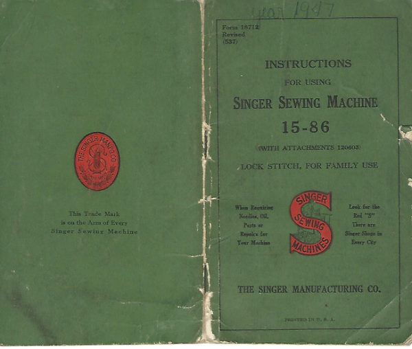
Singer 15-86
User manual
24 pages · EnglishRead →
From the ISMACS International. Original publisher and archive notices are retained.
Check the model and edition against your equipment.
PDF verified 2026-10-11.