Sewing machines
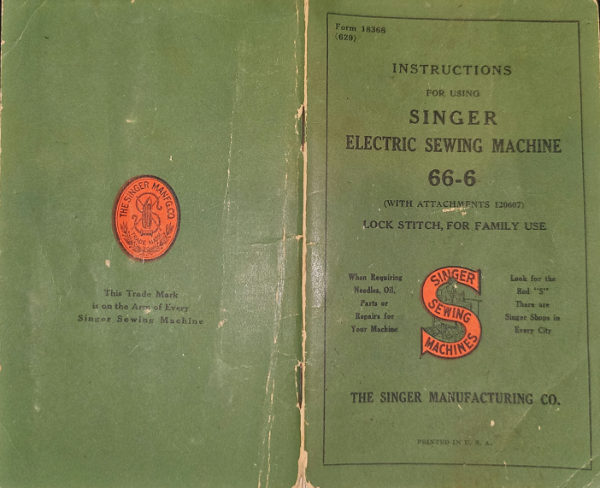
Singer 66-6 — User manual
User manual for Singer 66-6. 26 pages in English. Read the original PDF, download or print a copy without registration.
26 pagesEnglish25.3 MB PDF
Loading your manual…Open PDF directly
Document details
- Brand
- Singer
- Model / document
- Singer 66-6
- Document type
- User manual
- Language
- English
- Pages
- 26
- File size
- 25.3 MB
- Category
- Sewing machines
- Document date
- Not specified in catalog
Search available document text
Find a term, then jump to its page in the original PDF. Image-only pages may not be searchable; check the PDF for exact wording and diagrams.
Page 2 · Read text
18368

       THE IMPORTANCE OF USING
                                 INSTRUCTIONS
     SINGER LUBRICANTS FOR YOUR
                                                          FOR USING      ELECTRIC SEWING MACHINE
                           SINGER
     "The Best is the Cheapest"
                                  ELECTRIC SEWING MACHINE
     Use Singer Oil on Machine                66-6
       Knowing from many years experience
                                                                WITH ATTACHMENTS 120607
       the great importance of using good oil,
                                                             OSCILLATING HOOK, FOR FAMILY USE
      we put up an extra quality machine
         oil, in bottles, especially prepared for
      sewing machines.


    Use Singer Lubricant on Motor

      The Singer Motor Lubricant is espe-

      cially prepared for lubricating the

      bearings of the electric motor. This

      is a pure non-flowing compound which
      retains its consistency and possesses
      high lubricating qualities.


                    PRINTED IN U. S. A.                                                                             Е.8037

COPYRIGHT, U.S.A., 1915, 1921, 1923, 1924, 1926, 1928 and 1929,
         BY THE SINGER MANUFACTURING Co.                                              CABINET 40
       ALL RIGHTS RESERVED FOR ALL COUNTRIES

                                          THE SINGER MANUFACTURING COMPANY
View original page 2Page 3 · Read text
2                                                 3

                                                        Motor Can be Operated on Either Alternating
 To all whom it may concern:
                                                                   Current or Direct Current
   The placing or renewal of the name "Singer"
 (Reg. Û. S. Pat. Off.) or any of the trade marks
                                                                   The electric motor, which is located at the back
 of The Singer Manufacturing Company on
                                                                  of the machine, can be operated on either alternat- any machine that has been repaired, rebuilt,
 reconditioned, or altered in any way whatso-           ing current or direct current, as desired. The
 ever outside a Singer factory or an authorized            standard windings of the motor are for 110 volts,
 Singer agency is forbidden.                                                                 and motors can be furnished for any voltage between
                                                            100 and 250.
            DESCRIPTION
                                                                 Special motors for 32 volts direct current, and
   Machine 66-6, for family use, has an oscillating             for 50 volts alternating current and direct current,
 sewing hook and makes the lock stitch.                         have also been developed and are available.

    It is especially designed for operation by elec-
 tricity, having an efficient electric motor attached to              Points to Determine Before Connecting
the upright part of its arm, the speed of the machine                    Motor to Electric Service Line
being controlled by means of a knee lever.
                                                                 Obtain the following information from the Elec-
                                                          tric Light Company which supplies the electric
  It is also equipped with the electric Singerlight.
                                                            current for the circuit to which the motor is to
                                                          be connected:
  Cabinets 40 and 306, shown on pages 1 and 8,

respectively, are intended for use with Machine 66-6.                                                                    1. If current is direct, what is the voltage? The
When closed, either of these cabinets resembles an                                                            voltage must be within the range stamped on the
attractive desk or library table, the sewing machine                                                               name plate of the motor.
and motor being entirely concealed.
                                                                  2. If current is alternating, in addition to the

                                                              voltage, what is the number of cycles? The number

                                                              of cycles must be within the range stamped on the

                                                              name plate of the motor.

                                                              The voltage of any circuit and, if alternating

                                                              current, the number of cycles, can be verified by
                                                          looking at the name plate on service watt meter

                                                             installed by the local Electric Light Company.
View original page 3Page 4 · Read text
5               To Open Cabinet 40

                       (SEE FIGS. 2, 3, 4 AND 5)

     Raise the two leaves at the top of the table and
    the supporting rod will automatically spring out at


                  FIG. 2


                   FIG. 3
                                                                             I'IG. 4. RAISING MACHINE OUT OF CABINET 40

                                                                   Pull down the knee lever (Q) to the vertical posi-
                                                                  tion as shown in Fig. 5.


                                          E 8034


            FIGS. 2 AND 3. To OPEN CABINeT 40


 the left of the table. Allow the left leaf to rest on

 the supporting rod and the right leaf to hang loosely

 at the right of the table, as shown in Fig. 3.
   With the right hand raise the front hinged portion
 (K, Fig. 4) of the table, and at the same time place
 the left hand under the front side of the arm of the
 machine, as shown in Fig. 4, being very careful
not to touch the electric lamp or shade, and
raise the sewing machine head, then replace the                                                          27970
hinged portion of the table and lower the machine
so that it rests on the table, as shown in Fig. 5.               FIG. 5. KNEE LEVERONLOWEREDCABINeTTO40OPERATING POSITION
                                                                             ALSO ELECTRICAL CONNECTION
View original page 4Page 5 · Read text
7

   To Connectto Electricthe MachineServiceonLineCabinet 40

  Push the terminal plug at one end of the electric

cord as far as it will go on the three-pin terminal

block at the right of the machine, as shown at P in

Fig. 5. Attach the plug at the other end of the cord
to the nearest electric socket and the machine is
ready for operation.


           To Open Cabinet 306
                                                                                                                   E 7965
                  (SEE FIGS. 6, 7, 8 AND 9)

  With the right hand push in the lever (L, Fig. G)                         FIG. 7. To OPEN CABINET 306

at the right of the table and at the same time with
the left hand raise the hinged flaps of the table top,
                                                              Fold back the hinged flaps as shown in Figs. 7as shown at M, in Fig. 6.
                                                               and 8, having the catch (N, Fig. 7) enter the spring

                                                                 clip (0, Fig. 7).


                   M
                                                                                                                         6 7966
                                           E 7660


                                                                              FIG. 8. To OPEN CABINET 306
                FIG. 6. To OPEN CABINeT 306
View original page 5Page 6 · Read text
8
                                                                    9
    Raise the sewing machine head out of the cabinet
                                                        To Connect the Machine on Cabinet 306
 as shown in Fig. 4, being very careful not to                                                                           to Electric Service Line
 touch the electric lamp or shade, then turn down
 the hinged flaps of the table top and lower the ma-           Push the terminal plug at one end of the electric
 chine so that it rests on the table as shown in Fig. 9.          cord as far as it will go on the three-pin terminal
                                                                block at the right of the machine, as shown at P in
                                                          Fig. 9. Attach the plug at the other end of the

                                                                cord to the nearest electric socket and the machine
                                                                   is ready for operation.

                                                   CAUTION

                                                                When you have finished your sewing, always dis-
                                                                 connect the plug from the electric socket.


                                                                 To Close Cabinets 40 and 306

                                                              Remove the plug from the electric socket, also
                                                             remove the plug from the three-pin terminal block

                                                             at the right of the machine and coil the electric
                                                            cord around the machine.
                                     E8035
                                                     With the left hand grasp the machine around the
                                                            front side of the arm, turn it slightly back on its
   FIG. 9. KNEE LEVER LOWERED TO OPERATING POSITION             hinges, and at the same time, with the right hand,
                   ON CABINET 306                               raise the front hinged portion (K, Fig. 4, page 5)
             ALSO ELECTRICAL CONNECTION                                                         of the table, lower the machine head, being care-
                                                      ful not to touch the electric lamp or shade;

                                                              then lower the hinged portion (K).
  Pull down the knee lever    to the vertical posi-
tion as shown in Fig. 9.                                         On Cabinet 40 close the leaves, push in the sup-
                                                             sorting rod and swing back the knee lever.
  Fig. 9 shows the swing-out drawer at the left of
the table.This drawer is provided with holders        On Cabinet 306, unfold the hinged flaps of the
for spools, bobbins and oil can and has a compart-           table top and place them into position, then swing
ment for the box of attachments.                           back the knee lever.
View original page 6Page 7 · Read text
10
                                                                                           11

  To Ensure Perfect Action of the Machine
                                                        turn it until the bulb pin (T, Fig 10) is out of the
                                                         notch in the socket, then withdraw the bulb and
  The balance wheel must always turn over toward
the operator.                                          shade.

  Do not         run             the                 machine                         with                              the                                  presser
resting        on           the               feed                    without                            cloth                                  under                                        the presser                                          foot        R        S

foot.
  Do not run the machine when both bobbin case
and needle are threaded, unless there is material
under the presser foot.                    SINCER
  Do not try to help the machine by pulling the
fabric, lest you bend the needle. The machine feeds
 the work without assistance,
  The slide over the bobbin case should be kept
 closed when the machine is in operation.


     To Turn Singerlight "On" or "Off"

   Reach over the top of the machine and move the
                                                                                 57963
switch lever (R, Fig. 10) to the right or left as
 desired.                                                                                            FIG. 10


                                                               To insert a new bulb, pass the bulb through the      To Remove and Replace the Bulb
                                                              collar of the shade with the slot of the shade up-
                                                          ward. Hold the socket tightly with one hand and
 tightlyTo removewith onethe bulb,handholdand thewithSingerlightthe othersockethand         at the same time with the other hand press the
                                                                bulb into the socket with the bulb pin (T, Fig. 10)
 turn the shade halfway around until the pin (S,
       Fig. 10) for the shade is in the slot of the shade, then           in the slot and turn it until this pin is in the noteh.
 gently slip the shade off and allow it to hang free as         Then slip the shade over the socket, the pin (S,
 shown in Fig 10.                                               Fig. 10) for the shade entering the slot of the shade.
                                                              See that the pin (S) is in the groove of the shade
   Do not attempt to unserew the bulb. It is of
                                                             and turn the shade halfway around, or until it is
  the bayonet and socket type and does not unscrew.
 Press the bulb into the socket and at the same time           at the top.
View original page 7Page 8 · Read text
12                                            13

   Instructions for Operating the Machine                     To Take Out the Bobbin

                                                           Draw to the left the slide in the bed of the  Raise the presser foot (X, Fig. 11) by means of
                                                  machine and press the forefinger of the right handthe presser bar lifter (Z, Fig. 11) to prevent injury

to the foot (X, Fig. 11) and feed (W, Fig. 11).


                                                                                                                             E.5777


                                                          BB

                                              AA
                                                                                                  FIa, 12. REMOVING THE BOBBIN


                                     E7954
                                              upon the bobbin ejector (BB, Fig. 12) as shown
            FIG. 11. FRONT VIEW OF THE MACHINE
                                                       above; this will raise the bobbin so that it can easily
   Place a piece of cloth under the presser foot and       be taken out.
 let the foot down upon it.
                                                       Genuine Singer Needles should be used
                                                                 in Singer Machines.            To Start the Machine
                                                          These Needles and their Containers
   Turn on the electric current, press the knee lever                  are marked with the
                                                  Company's Trade Mark "SIMANCO." to the right. As the pressure on the knee lever is
 increased, the speed of the machine is increased,
 the speed being controlled entirely by the amount                                                           Needles in Containers marked
 of pressure on the knee lever. Operate the machine                                                                    "For Singer Machines"
 in this way, without being threaded, until you have
                                                             are not Singer made needles.
 become accustomed to guiding the material and
  operating the knee lever.
View original page 8Page 9 · Read text
14
                                                                  15
           To Wind the Bobbin
                                                               balance wheel hub, and the latch (HH, Fig. 14) will
  It is necessary to understand the stop motion         drop down and hold it. Then press the knee lever
                                                               the same as for sewing.
(EE, Fig. 13) by which the balance wheel DD,
     CC
     2                   DD,                                                     HH
                                                  GG
                                                        5                                                         FF
        SINGER
                                                             JJ

                            EE
                   E7953                                    4
   FIG, 13, MACHINE THRKADED FOR WINDING THE BOBBEX

 Fig, 13) enn be relensed when required, thus per-
mitting the winding of bobbins without running                                 * KK
the stitching mechanism.                                                                         E7952
  To relense the balance wheel (DD, Fig. 13), turn
                                                                                       FIG. 14. WINDING THE BOBBIN
the stop motion serew (EE, Fig. 13) over toward
you. It is necessary to hold the balance wheel
                                                 The end of the thread must be held by the hand
while loosening the stop motion serew.                                                                     until a few coils are wound and should then be
  Place the bobbin on the bobbin winder spindle                                                       broken off. Figs. 13 and 14 show the bobbin winder
(FF, Fig. 14) and push it up closely against the                                                properlythreadedand in
shoulder, having the small pin in the spindle enter                                                            bobbin, the bobbin winder is automatically released
the hole in the side of the bobbin. Put the spool of        from the balance wheel.
                                                                                             If the pressure of the rubber ring JJ, Fig.14)
thread on the spool pin (1, Fig. 13). Pass the          against the hub of the balance wheel is insufficient
end of the thread into the thread guide (2, Fig. 13)                                                              for winding the bobbin, loosen the adjusting serew
then up into the lower eyelet (3,Fig. 14) of the        (GG, Fig.14) and press the bobbin winder lightly
                                                               until the rubber ring is in contact with the hub of
bobbin winder thread guide, into the notch (4, Fig. 14)
and pass the thread through the hole in the left         the balance wheel; then tighten the serew (GG).                                                         Bobbins can also be wound while the machine
side of the bobbin (5, Fig. 14), from the inside. Press         is sewing
the bobbin winder pulley (JJ, Fig. 14) down on the
View original page 9Page 11 · Read text
18                                                        19

            To Set the Needle
                                                               5   Turn the balance wheel over toward you until the

 needle bar moves up to its highest point, loosen the

 thumb screw (V, Fig. 11) in the needle clamp (Y,

 Fig. 11) and put the needle up into the clamp as

far as it will go, with its flat side toward the right;

 then tighten the thumb screw. To select the correct

 needle see page 49.


           To Thread the Needle

           SEE FIG. 19 ON THE FOLLOWING PAGE
   Turn the balance wheel over toward you until the                             2
thread take-up lever (5) is raised to its highest                         3
point. Place the spool of thread on the spool pin
at the top of the machine, lead the thread into the
thread guide (1) at the left, down, under and from
right to left between the tension dises (2), into the

small wire spring (3), under the thread regulator (4)
at the left (not through the eye in the thread

regulator), up and from right to left through the                                            4
hole in the end of the thread take-up lever (5), down
into the eyelet (6), into the lower wire guide (7),               7
then from left to right through the eye of the
needle (8).
  Draw about two inches of thread through the
eye of the needle with which to commence sewing.

   Instructions for threading the machine for darning                                     E 7951

and for embroidery are given on pages 47 and 48.
                                                                           FIG. 19. THREADING THE NEEDLE
View original page 11Page 12 · Read text
20
                                                                    21
            To Prepare for Sewing
                                                              To Remove the Work
    Have the thread take-up lever at its highest point,
                                                                   Let the thread take-up lever rest at its highest
  then with the left hand hold the end of the needle
                                                               point, raise the presser foot and draw the fabric
                                                            back and to the left about two inches; pass the
                                                              threads over the thread cutter (LL, Fig. 20) and
  LL                                                          pull down lightly to sever them. Leave the ends of
                                                                  the threads under the presser foot.


                                                                        Tensions

                                                              For ordinary stitching, the needle and bobbin

                                                                  threads should be locked in the centre of the thick-

                                                                   ness of the material, thus:
                                                    E 7969         708

                                                                                     FIG. 21. PERFECT STITCH


                                                                       If the tension on the needle thread is too tight, or
        FIG. 20. DRAWING UP THE BOBBIN THREAD                                  if that on the bobbin thread is too loose, the needle

                                                                thread will lie straight along the upper surface of
turad, le bing it slack frowe to hand to thenitle.           the material, thus:


thus catching the bobbin thread; draw up the needle
thread and the bobbin thread will come up with it
through the hole in the throat plate (see Fig. 20).
                                                                           FIG. 22. TIGHT NEEDLE THREAD TENSION
Lay both threads back under the presser foot.

                                                                   If the tension on the bobbin thread is too tight,
          To Commence Sewing                                                                      or if that on the needle thread is too loose, the bobbin
  Place the material beneath the presser foot, lower             thread will lie straight along the under side of the
the presser foot and commence to sew, pressing the
                                                                  material, thus:
kneethe machine.lever (Q, Fig. 5, page 5) to the right to start
  When sewing thick material, it may be necessary,
                                                                                                                                                                       E113/9to turn the balance wheel over toward you by hand
to start the machine. This should also be done if
the machine stops when sewing across thick seams.                         FIG. 23. LOOSE NEEDLE THREAD TENSION
View original page 12Page 13 · Read text
22                                      23

         To Regulate the Tensions                           To Regulate the Length of Stitch

  The tension on the needle thread should only be             The length of stitch is regulated by the large
regulated when the presser foot is down. Having           thumb screw (KK, Fig. 14, page 15) at the front of
                                                            the machine near the bobbin winder.

                                                                   To lengthen the stitch, turn this thumb screw over

                                                                 to the right. To shorten the stitch, turn this thumb

                                                                  screw over to the left.


                                                          To Regulate the Pressure on the Material
                                   E7978
                                                                   For ordinary family sewing, it is seldom necessary

                                                             to change the pressure on the material. If sewing          FIG. 24. NEEDLE THREAD TENSION
                                                                  fine silk or flimsy material, lighten the pressure by

                                                             turning the thumb screw (CC, Fig. 13, page 14) on
lowered the presser foot, turn the small thumb nut
 (U, shown in Fig, 24, above, and Fig. 11, page 12) at           the top of the machine over to the left. To increase
the front of the tension discs over to the right to            the pressure, turn this thumb screw over to the right.
increase the tension. To decrease the tension, turn          The pressure should be only heavy enough to
                                                            prevent the material from rising with the needlethis thumb nut over to the left.
                                                        and to enable the feed to move the work along   The tension on the bobbin thread is regulated by
the larger screw (AA, Fig. 12, page 13) which is          evenly; a heavier pressure will make the machine
nearest the back in the bobbin case tension spring.           run hard.

 To increase the tension, turn this serew over toward
                                                              To Sew Flannel or Bias Seams
 you. To decrease the tension, turn this screw over
from you.                                                            Use a short stitch and as light a tension as possible
   When the tension on the bobbin thread has been            on the needle thread so as to leave the thread loose
                                                            enough in the seam to allow the goods to stretch once properly adjusted, it is seldom necessary to

 change it, as a correct stitch can usually be obtained           if necessary.

 by varying the tension on the needle thread.
                                                                       A Stitch to Ravel Easily

             To Turn a Corner                         can be made, if desired, by having the tension
                                                   on the needle thread so light that the bobbin thread   Stop the machine when the needle is commencing
                                                            will not draw into the goods but lie straight, as its upward stroke. Raise the presser foot and turn
                                                  shown in Fig. 23, page 21.
 the work as desired, using the needle as a pivot,
 then lower the presser foot.
View original page 13Page 14 · Read text
24                                                       25
            To Oil the Machine
                                                               Take out the thumb screw (MM, Fig. 25, page 24)
  To ensure easy running, the machine and stand          near the lower end of the face plate, raise the plate
require oiling and if used continuously should be         and slip it off over the head of the serew near the
                                                                 upper end of the plate; put one drop of oil into each

                                                                  of the oil holes and joints.

                                                             At the back of the machine is a round plate or

                                                              cover, fastened by a thumb screw; loosen the serew,
                 SINGER
                                                            turn the plate upward and fasten by tightening the
                                                          screw; turn the balance wheel slowly and oil the
                                                moving parts inside, then turn the cover down and
 MM                                                      fasten it as before.


                                           £ 7976


       FIG. 25, FRONT VIEW, SHOWING OILING POINTS

oiled each day. With moderate use, an occasional
oiling is sufficient. Oil should be applied at each
of the places shown by arrows in Figs. 25 and 26.                                                                 £ 4563

One drop of oil at each point is sufficient. Oil holes                  FIG. 26. OILING POINTS IN BASE OF MACHINE
are provided in the machine for bearings which
cannot be directly reached.
  To oil the mechanism under the slide, draw the        To reach the parts underneath the bed of the
                                                    machine, turn the machine back on its hinges andslide (see Fig. 25) to the left and after removing the
lint and dust which may have accumulated (see        apply oil to the oil holes and bearings indicated
instructions on pages 27 to 30, inclusive) put a         by the arrows in Fig. 26.
few drops of oil on the small piece of felt at the
 right of the bobbin ejector. The slide should then
be elosed.
View original page 14Page 15 · Read text
26
                                                           27
           To Lubricate the Motor
                                              To Clean the Stitch Forming Mechanism
  NEVER USE OIL ANYWHERE ON THE
 MOTOR. When the machine is shipped from the          After considerable use, the stitch forming mech-
                                                   anism of the machine may become clogged with
                                                          lint and this may interfere with the perfect opera-
                                                         tion of the machine.
                                + G      G                                            Occasionally remove the bobbin case from the
                                                        machine, as instructed below and on the following

                                                         page, and remove any lint, etc., which has accumu-
                                                       lated in the machine.


                                                      To Remove the Bobbin Case

                                                                (OPERATOR BEING AT THE FRONT OF THE MACHINE)
                               7364
                                                 Raise the needle to its highest point by turning
               FIG, 27, MOTOR GREASy TURES                                                   the balance wheel over toward you. Draw the
                                                       alide plate (NN, Fig. 28) slightly to the left, then
factory, the two motor grense tubes (GG, Fig. 27)          lift its right hand end and draw it toward the
are filled with sufficient lubricant for approximately      needle until it is disengaged from the spring in the
 six months' use, under ordinary circumstances.        bed of the machine.
  At least once every six months thereafter, these
grease tubes should be refilled with the Singer
Motor Lubricant, furnished with the machine. To
do this, insert the tip of the tube of lubricant into      NN
the hole at the top of each of the grease tubes
and force the lubricant through each hole until
both grease tubes are filled.


        To Lubricate the Controller

  Also occasionally lubricate the bearing points of
the controller mechanism located beneath the ma-                                         7971
chine at the right of the cabinet.
                                                                                    FIG. 28. SLIDE REMOVED
View original page 15Page 16 · Read text
29                 28

                                                          To Replace the Bobbin Case
    00                                                   (OPERATOR BEING AT THE FRONT OF THE MACHINE)
                                                              See that the needle is raised to its highest point
                                           and that the latch (00, Fig. 31) is raised from the
                                                       slot (PP, Fig. 31) and moved toward you.


   PP
                                      E7972

              FIG, 29.RAISING THE LATCH

  Insert the nail of the forefinger of the left hand

under the latch (00, Fig. 29), raise the latch just
high enough to clear the edge at (PP, Fig. 29)          RE
and then move it toward you.
  Under no circumstances must the screw
                              The loosening of this                              00
Brey will change the end or lose bet thin
the bobbin case and bobbin case position bracket.

                                                                                                        87974


                                                                                 FIG. 31. SHOWING THE BOBBIN CASE

                                                                            POSITION BRACKET


                                                  Hold the bobbin case between the forefinger and
                                                         thumb of the left hand, as shown in Fig. 30. Insert

                                                        the forked end of the bobbin case under the throat
                                                    plate so that the fork straddles the end of the
            FIG. 30. REMOVING THE BOBBIN CASE
   Hold the bobbin case between the forefinger and      bobbin case position bracket (RR, Fig. 31). Then
 the thumb of the left hand as shown in Fig. 30. Tit     with a slight twisting motion of the bobbin case
 the bobbin case to the left and at the same time      to the left and to the back, lightly press it down-
 slightly turn the right or forked end toward you
 so that it is moved out of engagement with the     wardly until the edge of the sewing hook engages
                                                    in the groove under the rim of the bobbin case. sewing hook. Then tilt the bobbin case toward
 the right and remove it (see Fig. 30).
View original page 16Page 17 · Read text
30
                                                           31
  Having set the bobbin case into the correct

position, lock the latch (00, Fig. 31) in the notch
(PP, Fig. 31) to hold the bobbin case in place.                  HINTS

                                                  Machine Working Heavily. If the machine

                                                          runs hard after standing idle for some time, use a

                                                             little kerosene in the oiling places, run the machine

                                                           rapidly, then wipe clean and oil.

                                                To Avoid Breaking Needles.  See that the
 SS
                                                             presser foot or attachments are securely fastened by
                                                       the thumb screw. Do not sew heavy seams or very

                                                         thick goods with too fine a needle. A large needle
                                                        and thread to correspond should be used on heavy
                                                  work (see page 49).

                                             See that the needle is not bent and avoid pulling
                                                      1975
                                                       the material when stitching.
              FIG, 32. REPLACING THE SLIDE                  Breaking.of Needle Thread. If the needle
                                                                 thread breaks it may be caused by:
Then replace the slide from the right, as shown
in Fig. 32, being careful to see that the two ends          Improper threading.
of the spring (SS, Fig. 32) enter the grooves on the          Tension being too tight.
                                                  The thread being too coarse for size of needle.underside of the slide.
                                               The needle being bent, having a blunt point,
   Genuine Singer Needles should be used
                                                              or being set incorrectly.             in Singer Machines.
     These Needles and their Containers            Breaking of Bobbin Thread. It the bobbin
            are marked with the
                                                         thread breaks it may be caused by:
   Company's Trade Mark "SIMANCO."
                                                               Improper threading of bobbin case.

                                                                 Tension being too tight.
        Needles in Containers marked
                                                      Skipping of Stitches. The needle may not be
             "For Singer Machines"
                                                             accurately set into the needle bar or the needle may
         are not Singer made needles.    2                                                         be blunt or bent. The needle may be too small for

                                                           the thread in use.
View original page 17Page 18 · Read text
32                                                                 33
INSTRUCTIONS FOR USING THE       FOOT HEMMER-Hemming and Sewing
       ATTACHMENTS                                  on Lace

     FOOT HEMMER Hemming                    Start the hem as previously explained, and when
                                                                  it is well started, raise the needle to its highest point.
  Raise the needle to its highest point. Remove

the presser foot and attach the foot hemmer in its


                                                                                         FIG. 34


                         FIG. 33                               Raise the hemmer to relieve its pressure on the hem,
                                                 pass the end of the lace through the slot in the side
place (see Fig. 33). Clip off the right hand corner
                                                             of the hemmer, under the back of the hemmer and
of the cloth, so that it will take the roll easily, turn
                                                       over the hem, as shown in Fig. 34.
up the edge about a quarter of an inch, insert it in
                                                        Take care that the hem is not displaced in the
the mouth of the hemmer and draw or push it along
                                                       hemmer and that the needle goes down through the
until under the needle. Then let down the presser
                                                      lace and hem together. Then let down the presser
bar and after taking two or three stitches, draw
                                                           bar and guide the lace over the front of the hemmer,
gently on the ends of the threads to help the work        keeping it well into the slot.
along till the feed catches it. In order to produce
a smooth even hem, the mouth of the hemmer must
be kept just full.                                   FOOT HEMMER-Felling

  Fig. 33 also shows what is known as a bag seam                                                               The two pieces of cloth to be felled should be laid
or fell, made by passing two pieces of fabric through         one over the other, right sides together, the edge
the hemmer together and hemming them down.         of the under piece being a little farther to the right
View original page 18Page 20 · Read text
36
                                                            37
  ADJUSTABLE HEMMER-Wide Hemming
                                                            instead of on the edge (see Fig. 39). After loosening   To make a hem more than 1 inch wide, loosen
                                                            the binder set screw and adjusting the binder, the the thumb screw in the hemmer and move the scale


                                                                                                                                                     2: 5120

                                                                                                   FIG. 39

                         Fra, 38
                                                           line of stitching can be brought nearer the centre,
 to the right as far as it will go, then swing is toward                this being more effective when making French folds.
you as shown in Fig. 38 and tighten the thumb
screw. Fold and crease down a hem of the desired                 TUCKER
width; pass the fold under the extension at the right
                                                           Retrove the presser foot and attach the tucker
of the hemmer, and the edge into the folder as
                                                          in its place. The width of the tuck is determined
shown in Fig. 38, and proceed to stitch the hem.
                                                          by the scale of figures nearest the needle, which
                                                            shows in eighths and sixteenths of an inch the dis-
          BINDER-Binding
                                                                  tanceTheofcreasethe edgeor ofmarkthe forfoldthefromsecondthe lineandoffollowingstitching.  Remove the presser foot and attach the binder in
                                                          tucks is determined by the scale nearest the operatorits place.Pass the binding through the scroll of
                                                  and this is set by the line in front of the needle holethe binder and draw it back under the needle.
Place the edge of the goods to be bound between
                                                            inadjustthe presserthe scalefoot.nearestFor blindthe operatortucks withoutso thatspaces,thethe scrolls of the binder and draw it under the needle.
                                                             figure opposite the line on the presser foot will be
Lower the presser bar and sew as usual. To make                                                          the same as that at which the guide is located on
 French folds, proceed as directed for binding except          the scale nearest the needle. To make spaces be-
that the fold is stitched on the face of the material         tween the tucks, move the front scale farther to the
                                                                                 left until the desired space is obtained.
View original page 20Page 21 · Read text
38                                         39

                                                                           Ruffler
  Having adjusted the scales for tuck and space as
                                                               Lines 1, 2, 3, 4 and 5 shown in Fig. 41 indicate
desired, fold the material and crease by hand; pass
                                                       where the material is to be placed for various

                                                                operations, as follows:


                                   B


                                                    F
                                                    E
                                                E 5115

                        FIG. 40

the folded edge between the spring and spur near
you, then between the two blades of the second
scale, and back under the presser foot; draw to the
right against the guide, lower the presser bar; see                                                5
that the lever which the needle clamp strikes is in its
backward position so as to form a crease for the        32                              E 7801
next tuck, then proceed with the first tuck.
  For the second tuck, fold carefully at the crease                                                                            FIG. 41. THE RUFFLER AND ITS PARTS
made by the spur and place the edge of the first tuck
 underneath and against the spur at the left. The                                                        Line 1-the correct position for the material to
 spur will serve as a guide and will also make a                                                                    which the ruffled material is applied.
 distinet crease for the next tuck. Always place the
                                                             Line 2-material to be ruffled.
 last tuck against the spur to ensure perfect work.
                                                              Line 3-the facing for the ruffle.
  When making the last tuck, the lever upon which
                                                               Line 4- the strip of piping material.
   the needle clamp strikes while tucking should be
                                                          Line 5—the edge to be piped.
 raised to its highest point; while the lever is in this
 position no crease for a sueceeding tuck is made            Refer to Fig. 41 when inserting the material in
                                                                   the ruffler.
 upon the goods.
View original page 21Page 22 · Read text
40                                            41

  The names and uses of the principal parts of the             To Adjust the Ruffler for Gathering
ruffler are as follows:
              (SEE REFERENCES IN FIG. 41)                         The adjusting finger (F, Fig. 42) is not intended
                                                          for gathering and should be moved forward or away
A—Foot-the part by which the ruffler is attached                                                             from the needle, as shown in Fig. 42.
       to the presser bar.
B-FORK ARM the section that must be placed
       astride the needle clamp.
C-ADJUSTING SCREW-—the screw that regulates the
       fullness of the gather
D-PROJECTION -the part that projects through the                                          D
       slots in the adjusting lever.
E- ADJUSTING LEVER-—the lever that sets the ruffler
      for gathering or for making a plait once at
      every six stitches or once at everytwelve
       stitches, as desired; also for disengaging the
       ruffler,when either plaiting or gathering is                                           E
       not desired.
F-ADJUSTING FINGER-the part which regulates
       the width or size of the plaits.                                                                                                    3 7828
G-SEPARATOR GUIDE- the guide on the underside
       of the ruffler, containing slots into whic the
                                                                                            FIG. 42
      edge of the material is placed to keep the
       heading of the rufile even; also for separating
       the material to be ruffled from the material to
       which the ruffle is to be attached.
H-RUFFLING BLADE the upper blue steel blade                                          Fig, 42) will
      with the teeth at the end to push the material         enter the slot marked "j" in the adjusting lever (E)
       in plaits up to the needle.                           when the lever is released  The ruffling blade will
J-SEPARATOR BLADE the lower blue steel blade        then move forward and back once at every stitch.
       without teeth, which prevents the teeth of the         Insert the material to be ruffled between the two
       ruffling blade coming into contact with the         blue blades, following the line 2 in Fig. 41. Draw
       feed of the machine, or the material to which         the material slightly back of the needle, lower the
                                                          presser bar and commence to sew.        ruffle or plaiting is to be applied.
                                                               To make fine gathering, shorten the stroke of the
    To Attach the Ruffler to the Machine              ruffling blade by turning the adjusting screw C, Fig
                                                              42) upwardly; also shorten the stitch. To make full   Raise the needle bar to its highest point and re-
 move the presser foot.  Attach the ruffler foot A,
                                                   Batting, lent en the strerescrew to(C)doingdownwardly,alady, Fig. 41) to the presser bar by means of the thumb
                                                         also lengthen the stitch. By varying these adjust- screw, at the same time placing the fork arm
                                                   ments, many pleasing varieties   work can be (B, Fig. 41) astride the needle clamp as shown in
 Fig. 42.                                                accomplished.
View original page 22Page 23 · Read text
42

       To Make a Ruffle and Sew it to a
                                                       the ruffle so that the wrong sides are together.        Garment in One Operation                                                    If
                                                              the facing is to be on the wrong side, place the right
                                                       sides of the garment and the ruffle together.
   Insert the material to be ruffled between the two

 blue blades, as shown in Fig. 43, following the line


                                                                                       FIG. 44

                                               17030                                                               Piping a Ruffle
                        FIG, 43                                Insert the material to be ruffled between the two
                                                  blue blades, following the line 2, in Fig. 41. This

2ufollowingto 15theto lineb2 cho1, in thuFig. 41.getProceedthat partithe bisametho
as for gathering.
  The edge of the ruffled seam can be bound by
using the binder.

       To Ruffle and Sew on a Facing
            in One Operation


   Insert the material to be ruffled between the two


ble salades, ol which the rue 2, is to be attached,
                                                                                                                          2 7837 underFig. 41.thePlaceseparatorthe materialblade, followingfor the facingthe lineover1,the
 upper blue blade, as shown in Fig. 44.following                                 FIG. 45
the line 3, in Fig. 41. The facing may be straight
or bias material. If the facing is to be on the      material must not be over 1¼ inches wide,
right side of the garment, place the garment and        it is carried through the ruffler with the finished
View original page 23Related documents and language editions
SingerPDF
Adjuster's for the Singer Model 20
Service manual
19 pages · EnglishRead →
SingerPDF
Singer 101-4 & 101-12
User manual
56 pages · EnglishRead →
SingerPDF
Singer 101-4 & 101-12 (black and white scan)
User manual
54 pages · EnglishRead →
SingerPDF
Singer 115
User manual
36 pages · EnglishRead →
SingerPDF
Singer 127 & 128
User manual
18 pages · EnglishRead →
SingerPDF
Singer 12K
User manual
12 pages · EnglishRead →
SingerPDF
Singer 15
User manual
36 pages · EnglishRead →

SingerPDF
Singer 15-125
User manual
38 pages · EnglishRead →
SingerPDF
Singer 15-22
User manual
13 pages · EnglishRead →
SingerPDF
Singer 15-30 / 15-87 & Generic 15 Class (rotated for printing)
User manual
14 pages · EnglishRead →
SingerPDF
Singer 15-30 / 15-87 & generic 15 class machines
User manual
14 pages · EnglishRead →
SingerPDF
Singer 15-86
User manual
24 pages · EnglishRead →
From the ISMACS International. Original publisher and archive notices are retained.
Check the model and edition against your equipment.
PDF verified 2026-10-11.