Sewing machines
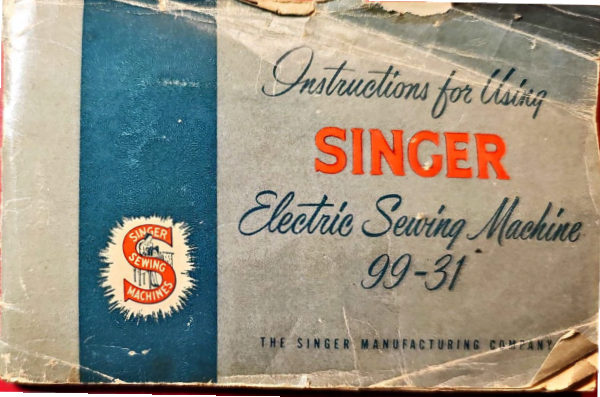
Singer 99-31 — User manual
User manual for Singer 99-31. 64 pages in English. Read the original PDF, download or print a copy without registration.
64 pagesEnglish12.0 MB PDF
Loading your manual…Open PDF directly
Document details
- Brand
- Singer
- Model / document
- Singer 99-31
- Document type
- User manual
- Language
- English
- Pages
- 64
- File size
- 12.0 MB
- Category
- Sewing machines
- Document date
- Not specified in catalog
Search available document text
Find a term, then jump to its page in the original PDF. Image-only pages may not be searchable; check the PDF for exact wording and diagrams.
Page 5 · Read text
WHA    -1  E  E VICE MEANS TO YOU
   Over  1400          ~E !ING  CENTERS   in
    the    nite           alone  ser e wo1nen who
    sew.
     I STRUCTIO J  by skilled  teachers  are given
    to purchasers of new SINGER Sewing.Machines
    at no  extra  charge. Budget  courses  in- hon1e
   dressmaking,  home  decoration  and  Fashion
    Stitching are also available.
  REPAIR SERVICE  is as co9venient  as your
   telephone. Whenever  your n1achine needs ad-
     j us tmen t,  a  trained  SINGER   representative
    will call  at your home. SINGER*  Service as-
   sures  excellent  workmanship,  guaranteed   re-
    pairs  and  SINGER~'f  parts.  An  esti1nate  is
   given for your approval.                 ./
   And  remember,   your  SINGER  SEWING
  CENTER  and  the SINGER  Service  car  are
    identified by  the  f arnous SINGER  Red  "S".
• • • • • • • • • • • • • • • • • • • • •
             r.                                                   3
View original page 5Page 6 · Read text
Before  Inserting   Electric  Plug

                                           be  sure  that  voltage  and  number   of
                                                 cycles stamped  on motor  nameplate   are
                                                within  the range marked  on the electric
The SINGER~:  Electric Motor                                             meter   installed   by, the  electric  power
is loc1.ted  at  the back  of  the machine      company.
and  is regularly  furnished  for operation
                                                                                               I            To Connect  the Machine  toon  an  alternating   .current   of  110-120
                                                 Electric  Service Line volts, 2 5-7 5 cycles, or on 110-120  volts          .                     .
 direct  current.   Special  mot'ors  can  be     Attach  the  terminal  plug  at the end· of
 furnished   for  direct  or alternating   cur-      the electric  cord  to the nearest  electrical
 rent  for  any  voltage  between  50 and       outlet,  and  the machine  is ready  for op-
250, and  for 32 volts  direct  current.    _      eration.


                                                4
View original page 6Page 7 · Read text
0   0


                                               Before  replacing   lens B make  sure lens ~
                                                    spring   is in place.  Then  insert  lens and
                                                       • turn   it  approximately  ½ turn  to hold
                                                 lens behind  stops.                          .
                                                   •   I                    CAUTION:  Wherr you have  finished To turn  the  spotlight  "on"  or  "off",                                           your sewing, always disconnect the plug  turn. th.e knurled switch A, Fig. 2 over                                         from the electric outlet.  to the right.·             r    )   "'

 To Remove~    and Replace  the Bulb  u
               /
 To .. remove  ·bulb,  first disengage  lens
  B, Fig. 2 by pressiqg it inward and turn-
  ing  it ½ turn  to  clear the  lens stops.
  Lens will then drop out into your hand.
  !he _bulb is !hen removed by unscr~w~
  1ng 1t from  its socket in the  spotl'.ight.,~
  To  replace,  screw  the  bulb  into  the
   socket, then replace the lens.                               Fig. 2. Spotli~ht

•   4
                                                    5                                                                              .
View original page 7Page 9 · Read text
If the machine  i  u ed  ontinuou  Iy   it
 should  be  oiled  dail   .  If  moderately
 used  an occasional  oilin    i    ufficient.         0 IL             ' Apply one drop  of  oil  to each  of  the
places indicated  in Figs.  3, 4, 5 and  6,        01
and carefully  clean  the machine   to in-
sure smooth  and  satisfactory  perform-
ance. Oil holes are provided  in the ma-
chine for bearings which  cannot be di- •
rectly reached.
                                                                                                                                                                                                                  '-  .  01Remove face plate D, Fig. 3 by taking
out screw C and loosening  screw E near
the  top  of the  plate.  Slip  plate, from
under screw E. Oil the points  indicated
in Fig. 4 and then replace  face plate D.

                             Fig. 4. Face Plate Removed,
                            Showing  Oiling Points
                                                7
View original page 9Page 10 · Read text
OIL
                 OIL

                 OIL
                      OIL OIL  'OI
Fig. 5. Oiling the Sewing Hook
                                                  Fig. 6. Oiling  Points  in Base  of  i\tlachine

                                                                                                                                                           L..

     To  oil the n1echanisn1 under  the  slide,     the  right  of  the  bobbin  ejector   at  F,
     draw  the s.lide to the lefL ( as shown  in    Fig.  5. The  slide should  then be closed.
      Fig. 3) and, after removing  the lint and    To  oil the parts  underneath   the bed of
      dust which may have accumulated   ( see     the n1achine,  turn  the ma  hine back on
      instructions  on  page   31),  put  a few      its hinge  and apply  oil to the oil hole
      drops of oil on the small piece of felt at    an  l bearing   indi  ated  in Fig. 6.

                                                   8
View original page 10Page 11 · Read text
0     •            • •                                                               • •

             The  motor    requires     no   lubrication.


                                                                       IBELT
See that the belt has the correct tension.
This tension should be only enough  to
keep the belt from slipping.~ If t~e belt
tension  is  incorrect,  loosen  the  screw
HH,  Fig. 7, about  qne· turn and "allow•
the motor  to drop downward   until  the
belt  has   the   correct   tension,   then
tighten  the screw HH.


                                                            Fig. 7. S,wing Motn   QII 99 MadJi1#


                                               g
View original page 11Page 13 · Read text
•••••••
                                                                            ~

                                                              "                        ·,,,              $                        4
               ~~~  ~i~w~-;-:.tl#&~~.r.i~           screw H. A screwdriver  slot  is provided
                                                     for  stronger   clamping   of  needle  (re-
                                                quired   for  attachments    driven  from
                                              needle clamp  hub).For perfect  stitching,  thread  should  be
selected  according   to   fa bric   to  be
stitched and needle must be correct  size
for  thread  which  must   pass   freely
through  eye of needle.

TO SET THE NE·EDLE
Select  the  correct  needle  according  to
the table on page  10. Be sure that needle··
is not  blunt  or  bent. Raise  the needle
bar  to  its highest  position  and  loosen
thumb screw H, Fig. 8 in needle clamp.
Push needle with   its  flat  side  toward
 the  right  up  into needle clamp  as far
 as  it  will  go, then  tighten  the thumb              Fig. 8. To Set the N eedJe

                                                  11
View original page 13Page 14 · Read text
•  • • • •  •  •  •      • • • • • • • • • •

                                See Fig. 9
                                   Place spool of thread on spool pin
                                  Raise take-up lever S to its highest point
                              Lead thread in to thread guide 1
                       Down and from right to left between
                                     tension discs 2
                                   Into the loop of the take-up spring 3
                           Under  the  slack  thread  regulator  4
                                 (not thro_ugh the eye in the thread
                                   regulator)
                       Up and from right to left through hole
                                      in take-up lever 5
                       Down through guide 6 on face plate
                      Down through the lower wire guide 7
                           From left to right through the eye of
                                     the needle 8
                        Draw  about  two  inches  of  threa i
                                through the eye of the needle with
Fig. 9. Upper Tbreading          which to begin ewing.
                                      12
View original page 14Page 17 · Read text
If  thr ad d  s  not  wind  even! y  on
 obbin   loosen  screw  which   holds
thread guide 3, Fig.  11.
Turn guide to left if bobbin winds high
on right.
Turn guide  to  right   if bobbin  winds
high on left.
When guide is proper 1y cen te:ed, ~hread
will wind evenly across bobbin. Tighten
guide clamping screw.
If the  pressure of the  bobbin  winder
pulley N,  Fig.  12, against  the hub of
the hand wheel is insufficient for wind-
ing the bobbin, loosen clamping  screw
P, Fig. 12, and set the bobbin winder
pulley in more positive contact with the                                             Fig. 12. Bobbin Winder Adj1,stm  nt
hand wheel hub. Then tighten clamping
screw P.
View original page 17
Page 20 · Read text
hold the needle thread,  leaving  it slack
                                        from the hand  to the needle. Turn  the
 Have  the  thread  take-up  lever  at  its    ,hand wheel over toward  you until  the
highest  position.  With  the  left hand,  •   needle moves down and up again  to  its
                                               highest  position,  thus catching  bobbin
                                                 thread. Draw up the needle thread and
                                                the bobbin thread  will come up with  it
                                            through  the hole in the throat  plate as
                                     shown in Fig.  1 7.
                                     Lay both threads back under the presser
                                                foot diagonally  across the feed, to the
                                                   right or left, depending upon which side
                                               of the needle the material   is to be lo-
                                              cated so that when  the presser  foot  is
                                                   lov.rered, the threads  will be firmly held
                                         between the feed and the presser foot.
Fig. 17. Drawing Up the Under Thread

                                              18
View original page 20Page 21 · Read text
TO START  SEWING


Be sure  to have  thread  take-up  lever  5, Fig.  9
in  its highest   position.
Place  n1aterial  beneath  the  presser  foot Q, Fig.
18, turn  the hand  wheel  to bring  the point  of the
needle  into  the  n1aterial,  then  I wer  the  presser
foot by n1eans of  presser  bar  lifter R and  start
to sew.  Press  the  controller   pedal   to  start   the
machine.  The  speed  depends  upon  the  amount
of pressure  on the controller  pedal.
Some  materials,   such  as  soft  finished   sheers,
nylons,   jerseys,   tricots  and   other   elastic   and
spongy  textiles,  require  a slight  an1ount  of  assist-
a_nce in feeding  the goods  during  sewing  opera-
tions.

                           Fig. 18. To Start Seu·ing

                                                    19
View original page 21Page 22 · Read text
H    •  ·er, t   11u h pull will stretch  the   BASTING
 seam   create   irreo-ular   stitching   and     The longest  stitch,     o. 6, on stitch in-
 ben   the needle. Mo  t n1aterials  require      dicator  plate  is satisfactorf   fo~ basting
  onl., guidin   f  r be  t sewing results.         and  is easily remov_ed by cl~pp1ng every
                                                     sixth  stitch  and w1thdraw1ng  the long
 The  machine  ~rill sew  its own  thread                                               continuous   thread.
 when se~Ting from one piece of material                                         Machine   basting   is  firmer,  more even
  to another.  However,   it  is not recom-                                           and much  quicker  than  hand  basting.
 mended  that any sewing be done with a
                             TO SEW  BIAS  SE  threaded  machine  unless  some  fabric
                                        Use a short  .stitch  when  sewing  bias or  is under  the presser  foot.
                                             curved  seams  to  increase  the  elasticin·
                                                 of the seam and  to prevent  seam failu{e
                                             under  strain.  No  change  in tensions is TO   R  A CORNER                                                    required.
 Pivot on the point  of the  needle.  Stop   TO REMOVE  THE
 the machine when  the needle  is in the     Stop the machine with the thre d ta ·e-
 fabric on  its upward  stroke.  Raise  the     up lever;,  Fig. 9 at its highest point.   .
presser  foot  and  turn   the  work   as                                          Raise  · the  presser  foot  by means ot
desired,  the.n lower  the presser foot and                                              presser  bar  lifter R, Fig. 18 draw theresume sewing.                                                fabric  back and  to the  left and  ever
                                              20
View original page 22Page 23 · Read text
the thread  on thread  cutler  S, l;ig.  18.
Pla e end  of threads under presser  foot.
CAUTION:                         .                .
When  the machine  is not 1n use,  raise
the presser foot by r:n~ans of presser bar
lifter R to prevent  1nJury to the presser
foot and the feed T, Fig.  18.
 0 REGULATE LENGTH
OF STITCH
The machine  is adjustable  to make from-
6 to 30 stitches per inch, as indicated  by
the  numerals  on  the  stitch  indicator         Fig. 19. To Regulate  Stitch Length
plate.
The  "red  dot"  indicator  U,  Fig.  19    Move the lever at V until  the·  ·r d doc"
in the slot at the left indicates  the stitch       indicator U  is at the d   ir d  tirch   er-
setting.                                              ting.  Then  turn  thumb  nut V  in\  ard
To regulate  the  length  of  stitch,  turn       until    it  touch     indicator   place.  The
thumb  nut V,  Fig: 19 on lever away     machine  is now      t to   ti tch the de ired
from the stitch  indicator  plate as far as    numb  r  of   tirche   p r  inch  in  a for-
 necessary.                                       ward  dir  ction.
                                                  21
View original page 23Page 24 · Read text
t           E DIR.ft"l~  , ,                                                       e  e  o  •   •  o  •   •   •                                                                       •   •
         F EED                                                          n1aterials. The pressure  should  be only
                                              heavy enough  to prevent  the  material
                                             from  rising with  the needle and  to en-
                                                    able the feed  to move  the work  along
                                                 evenly  without   side  creeping.  To  in-
    For Back Tacking,   raise the lever to     crease  the  pressure,   turn   the  thumb
     the  upper  end  of the  indicator   plate.     screw W, Fig.  2 0 clockwise  or down-
    The machine  will  then  stitch  in a re-     ward. To lighten  the pressure,  turn  the
     verse direction, making  it easy to fasten     thumb  screw W so that   it  scre-\VSup-
     the ends of seams.                          ward.


   TO REGULATE  PRESSURE
   ON  PRESSER FOOJ
    For ordinary sewing, the pressure  of the
    presser foot on the material  seldom  re-
    quires  changing.  Heavy  materials   re-
    quire more pressure  than  light  weight

                     Fig. 20. Thumb  Scretv for Regulating
                          Pressure on Presser Foot
                                                   22
View original page 24Page 25 · Read text
Thread  Tensions
 For perfect stitching, the tension on the ~-~
 needle and  bobbin  threads  must  be               Fig. 21. Perfect  Stitching
 heavy enough to pull the threads  to t!1e
 center of the thickness of the material
 and make a firm  stitch,  as shown  in
 Fig. 21. If the needle thr.ead lies straight
 along the top side of the material,  the                                  ---~ tension on  the  needle  thread   is  too       ~   ~
 heavy or  the  tension  on  the  bobbin                                                   Fig. 22. Imperfect  Stitching
thread is too light, as shown in Fig. 22.
If the bobbin thread  lies straight  along
the underside of the material,  ·the ten-
sion on the needle thread  is too light or
the tension on the bobbin thread  is too
heavy, as shown in Fig. 23.
                                                   Fig. 23. Imperfect    titchin


                                                 23
View original page 25Page 26 · Read text
TO             L

                                                               is  obtained.  Each  higher  number  de-
                                                  notes increased  tension.
  Th  ten ion  n the needle thread  can be    To  decrease   tension,   turn  the thumb
   e ted  onl  ~ hen  the  presser  foot  is     nut Z gradually   to  the  left  (counter-
                                                clockwise)  until  the required  tension  is  do" 1n.
                                                   obtained.  Each  lower  number  denotes  The  numerals  «O"  to  «9"  on  dial  X,
                                                       less tension.  Fig. 24 indicate  the different  degrees of
  tension that can be obtained. The num-     The tension indicator Y is marked  with
  bers do  not  denote  size  of  thread  or      the signs + and  -,  which  indicate  the
  ounces of tension.                               direction  in which  to  turn  the thumb
                                                nut Z for more or less tension. When the tension has been correctly  set,
  note the number  at the indicator  line Y,
 Fig. 24 so that  this  setting may be re-
 gained should  the tension be altered  for
 special work.
To  increase  tension,   turn  the thumb
nut  Z,  ~ig.  24 ~radually   to  the  right
( clockw1se)   until  the required  tension

                 Fig. 24. To Reg11/a1e
             Needle Thread Tension
                                               24
View original page 26Page 27 · Read text
The ten ion on the bobbin thread  is reg··
ulated b  the screw A, Fig. 25 which  is
nearest the center of the tension  spring
on the outside of the bobbin case. To in-
crease the tension, turn screw A over to
the right. To decrease  the tension,  turn
this screw to the left.

When  the tension on the bobbin  thread
has been once properly   adjusted,    it  is
seldom necessary to change  it. A cor-
rect  stitch  can  usually  be obtained  by
varying the tension on the needle thread.


                                                                                                                                           llJiOll                                             Fi  .     .  obbi  Thr   T
                                                   2
View original page 27Page 28 · Read text
TO                         I
                 ENS,IDN
                                                         press in the dial to disengage the pin C,
                                                           Fig. 26 in the thumb nut from the dial,
        Turn  the thumb  nut B, Fig. 26 to the     and remove  the thumb  nut  and  dial,
            left until the numeral  "O" on the num-      stop washer  E, tension  spring  F, indi-
         bered dial stops opposite the center line      cator G,  the two  tension  discs L, and
        between the plus and minus signs, then      the thread  take-up  spring N.

                  J                                      C B
             l
                   t                  N

                       Fig. 26. Needle  Thread  Tension Disassernbled

                                                   26
View original page 28Page 29 · Read text
A
 -•-it   tB,RIAD TENSION


  l lake sure that the tension rel~asing pin
J is in place in the stud  0,  then place
 the thread take-up  spring on the stud,
having the tail  ( inside the coil)  of this                                                          ,,
spring in one of the grooves T of the
                                            Fig. 27. Needle  Thread Take-up Springstud, and with the large loop N of the
spring resting  against  the thread  take-
up spring_regulator  at M, Fig. 27.

~i~. 27 shows the spring in correct po-
sition on  th~  stud.  The   tail  of  the
spring  is not  visible  in  these  illustra-
ti~ns,_b~t its locatiqn, inside the spring
coil, 1s indicated by K, Fig. 26.

                                                          •

                                             Fig. 2    eedle Thre d Tension
                                            27                                                Discs   i • e,nble I
View original page 29Page 30 · Read text
,.,

                                     F E O C B
 Pl~ce the  t\"\o ten ion  discs L, Fig. 22
 \vith  their  flat  thread-bearing   sides  to-
  ether  in position  on  the  stud O and
    ith the loop N  of the thread  take-up
 spring  straddling  the discs L as shown
 in Fig. 28. Next replace the indicator G
  v. i th the large open side facing  the end
 of  the  stud and  so  that  the  plus  and
 minus marks will be at the top with the       Fig. 2!). Reassembling  Needle  T bread
 minus sign to the  left. Then  insert  the                     Tension                                                                           .....
 tension spring F in the indicator  with
                                                    clear the  first  (half)   coil of the tension the first (half)   coil of the spring  strad-
                                                 spring  as shown  in Fig. 30. dling  the  lower  half  of  the  stud,  as
 shov.'n in Fig. 29. Place the stop washer     Next  place  the numbered   dial on  the
E on the stud so that  the extension  will                                                 stud so that  the numeral  "2"   is oppo  ice
 be above the tension stud.                                                  the  stop  washer  extension,  then  pu h
                                                  the dial  to compress  the spring,  o that
If  the  spring  and  stop  washer  are  1n      the thumb  nut  can be turned   nto  the
correct  position,  the  extension  S  will        stutl,  carefully  guiding  the pin C in the

                                              28
View original page 30Related documents and language editions
SingerPDF
Adjuster's for the Singer Model 20
Service manual
19 pages · EnglishRead →
SingerPDF
Singer 101-4 & 101-12
User manual
56 pages · EnglishRead →
SingerPDF
Singer 101-4 & 101-12 (black and white scan)
User manual
54 pages · EnglishRead →
SingerPDF
Singer 115
User manual
36 pages · EnglishRead →
SingerPDF
Singer 127 & 128
User manual
18 pages · EnglishRead →
SingerPDF
Singer 12K
User manual
12 pages · EnglishRead →
SingerPDF
Singer 15
User manual
36 pages · EnglishRead →

SingerPDF
Singer 15-125
User manual
38 pages · EnglishRead →
SingerPDF
Singer 15-22
User manual
13 pages · EnglishRead →
SingerPDF
Singer 15-30 / 15-87 & Generic 15 Class (rotated for printing)
User manual
14 pages · EnglishRead →
SingerPDF
Singer 15-30 / 15-87 & generic 15 class machines
User manual
14 pages · EnglishRead →
SingerPDF
Singer 15-86
User manual
24 pages · EnglishRead →
From the ISMACS International. Original publisher and archive notices are retained.
Check the model and edition against your equipment.
PDF verified 2026-10-11.