Film cameras
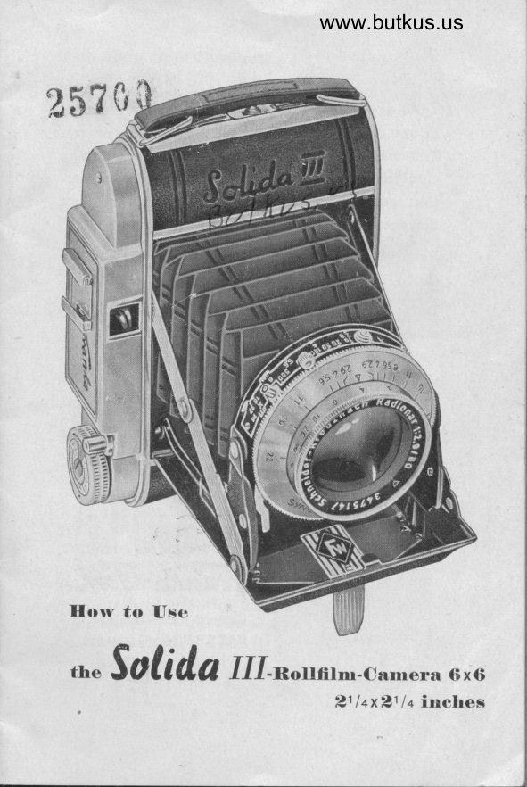
Solida III User manual
User manual for Solida III. 20 pages in English. Read the original PDF, download or print a copy without registration.
20 pagesEnglish6.1 MB PDF
Loading your manual…Open PDF directly
Document details
- Brand
- Solida
- Model / document
- Solida III
- Document type
- User manual
- Language
- English
- Pages
- 20
- File size
- 6.1 MB
- Category
- Film cameras
- Document date
- Not specified in catalog
Search available document text
Find a term, then jump to its page in the original PDF. Image-only pages may not be searchable; check the PDF for exact wording and diagrams.
Page 3 · Read text
lt   I
U\J e apprecirate the confidence you harre shown
  in our pro,ducts by acquiring the 'Solida' camera.
 For near,ly 40 years we h,ave been manufacturing
  cameras, an'd our experience in camera construc-
 ,tion gained over sudr a long period will not
  disappoint you.
 Your dealer will be glad to assist you with advice
  that will help you to achieve the best results.
 Before ursin'g your sa,m,era, please read the in-
  structions carefutrly and pnactirse the various
  manipulations at leisure. Tlhis will save you much
  disappointment and annoyance.
 Under no circumstances attempt to corre'ct trouble
  yourself or use force. Almost invariably the
 trouble will thus be aggravated. Take y'our
 camera back to yo'ur dealer or send it to the
  Distributors for attention.


                                                                                                                           t          Ftln-I6t                         Camera-Works establ. l9lo                                                                                                                :
                     BAYRE UTH (Germany)
View original page 3Page 5 · Read text
tihe protective p,aper must face the lens. Break the
adhesive strip of the flI,m, pull out 4" or 5" of the
protectiv.e paper ,and swing the spool carrier bach
intro the spool chamber. Thnead the pointed end of
the pnotective paper (36) into the wider s,lot (35) of
the upper empty spool so that is protrudes from the
narrower sl,ot. Fohd the u,pper spool cLarrier (3a) with
the e,mpty spool, badr into the spool cha'mber; for
this purp'oise it  is necessary to pull out the fitrm
winding knob (22) Turn the fllm winding knob (22) in
the directi,on of the arrow until it engages in the slot
of the empty sp,ool, thereby enabling the film winding
knob to spring back into position.
Wind 2-3 layers of the protective pap,er onto the
emty spool (35) taking care that the film paper is
running absolutely straight without crumpling at the
e'dges of the spool. Now, fol,d down the back (32) and
lodr (28).
Wind the fitrm, wi.th the back closed, until the dots
become visible in the film window (33)'and conti'nue
to wind cautiously until the number 1 appears. The
fllm is now ready for the flrst exposure. After taking
a picture, it  i's advisable to move the film at once to
the next number.

Removing the Exposed Film:
After the last exposure turn the film winding kno;b
(22) until no more of the protective paper is visible
trhrough the film window. Then o,pen the back (32),
wind the fll,m tight upon the spool and seal it wi'th
the attactred adhesive strip. Pul,l out the fllm wind-
ing knob (22) swing the spo,ol oarrier, with the full
spool, upward and rernove the fiIm.

4
View original page 5
Page 6 · Read text
www.butkus.us
Changing the Empty Spool:
Remove the empty  spool  f rom the l,ower flIm
chamber and insert it into the upper fiIm chamber
as described above.
Proteetive Cover for Panehrornatie
Fihns
The sensitivenes,s of
panchromatic films is
so great that the intru-
sion of l,ight for hours
or d,ays through the
red film window might
fog the filrn. The'refore   38
the camera is equipped                        J3with a device to cov,er
the flIm window. This
cover should be kePt
shut all the time and
opened built in or'der
to cont,rol the nurnbers                                    Picture 3while moving the flIm
for the next exp'osure. The flim window cover is
controlled by means of the sliding button (38).

Opening the Carnera,
Pres,s the button (30) and the base-board (21) will
open. Pull down the base-board (21) until both s'truts
(25) clicl< aud'ib1y into the notch, otherwise the base-
boarrd will not be fast and the lens not in the c'orrect
position. This may cause unsharp pirctures.
View original page 6
Page 7 · Read text
The Lens
                             (picture 5)
                         Focussing the lens:
                      Turn the lens mount so
                         that the pointer (11) is
                             at oo; thus the carnera is
                       focussed for  "infinity"
                        that  is, for  distances
                       beyond 50 feet. For 'o,b-
                               jects of a lesser distance,
                          the adjustmenb is effect-
                       ed by setting the mount
                         of the front lens to the
                          desired number of feet.
                         Estimate or, better still,
                       me'asure the  distance
                     from the object to the          Picture 4                    camera and turn  the
                          Iens mount sro that the
pointer (11) tallies with the approbiate  dist,ance.
engraverd on the lens mount. Where there is no en-
gnaved flg,ure for the distance measured, the pointer
should be set appropriately between the ne,arest two
flgures; €. 9., stroul,d the distance be 7 feet, then set
the point,er ,mridway between the flgures 6 and B on
the lens rrlou,nt. Alternatively, change the position of
the camer,a or the obje,ct so that the distance coin-
cides with the appr,opriate figure on the lens mount.
After the expo,sure, and before closing the camera,
always return fr'ont lens to oo otherwise the strong
preissure of the close'd bas'e-board on the lens would
force the len,s panel out of position and unsharp
pictures would result.

6
View original page 7Page 8 · Read text
www.butkus.us           6  78    I  /0


                       Picture 5
Depth  of Foeus
The depth of focus is increased by stopping down
the lens, on either side of the pointer (11) on the
shutter ring, 'is engraved the various stop settings
from f 2,9 to f 22. When the lens mount (1) has been
set for any given 'distance, the diaplrragm should
be stopped,down to the stop adjacent to the red d,ot
on the le,ns m,ount. The di,aphragm is adjusted by
rrreans of the leve'r (6) at the top of the lens mount.
At f 2,9 the lens is fully aperr and admits the greatest
anr,ount of l,irgrttt, whilst at f 22, the aperture  irs redittc-
ed to its rs,naal,lest di'ameter an,d admits correspon'd-
View original page 8Page 9 · Read text
IlISTRUCTIOl{ FOR TH E PROl{IOR-SVS

                                                             (Size 0) with Light Yolue scole


Chqrqcteristic Feqtures of the Pronlor-SVS

The Pronlor-SVS is on oulstonding exomple of Germon cqmero shutler design. lt enobles photogrophs
to be token with electronic flosh ol flosh-bulbs ot oll shutter speeds, while the occurolely groded
exposure times from  l sec to r/roo Sec mokes successful picture-toking in doylight o simple motter.
Even fosl qction shots of sporting events present no difficulty. The built-in self-timer, set oulo-
moticolly in the some operation thqt cocks the shutter, ollows you to oppeor in the picture yoursell
whenever you wish. Since speed qnd operture ore coupled, corresponding volues con be set in o
single operolion on o speciol exposure scole provided for this purpose.
View original page 9Page 11 · Read text
Adiustment for the fype of exposure to be mqde
This is effected by meons of the synchro lever os follows:
1. Exposures without flosh: Setting M or X
2. Exposures with flosh: Settings os indicoted in the toble
5. Exposures employing deloyed oclion: Setting Y. For deloyed oction exposures with flosh the
  some inslructions opply os with setting X (see toble).
    It should be noted thot the synchro lever con be set to V only when the shutter hos been cocked.
To moke on exposure, therefore, oll thot is required, oport from cocking the shutter ond selecting
lhe correct stop ond shutter speed, is to move the synchro lever to the desired position.
Two importont   odvontoges.
o) The synchro lever con be freely moved to ony position even when lhe shutter hos been cocked, so
   olterotions con be mode of ony time os required.
b) When on exposure with deloyed oction hos be'en mode the synchro lever outomoticolly returns
   from Y to X.
Hondling the speed-qperlure coupling
The coupling level hos two positions, morke'd wilh o dot ond o circle respectively.
 1. The posilion mqrked with o dol.
  At this position of the lever speed ond operture ore co,upled. This meons thot when the speed
View original page 11Page 12 · Read text
www.butkus.us

  setting ring is turned the corresponding lens stop is outomoticolly set ot lhe some time, thus
  ensuring uniformly exposed pictures.
Eromple:           Speed: 1/a     rls      l/so       rlao       r/rzs       l/soo S€C
                    Stop:  22    16    11      8     5.6     3.5
Nole: The jump from l/rzs sec to l/soo S€c represents lrlz ol the normol grodotion, so the corresponding
chonge in operture size is likewise  lrlz ol the normol grodotion.
The foct thot the poirs of speed-operture volues os quoted obove ore oll equol in respect of the
omount of light possing through the lens mokes it possible for them to be expressed by q single
number, the so-colled light volue. The common light volue for the poirs in the qbove series is 12.
 It should be noled thot the speed ring must be set only of click siops ond not of intermediote
 posi,tions on the scole.
2. Ihe position morked with q circle:
At this position of the lever speed ond operlure ore not coupled. The setting ring ond stop lever
con therefore be moved independently of eoch other in the usuol monner. A specific speed-operlure
combinotion is obtqined eilher by seporote setting of the corresponding speed ond operture
volues os reod off from on exposure meter, lor exomple, or by setting the oppropriote volue o,n
the light volue scole, ofter the coupling device hos been engoged by setting the lever to the
position morked with o dot. The coupling device hos click stops of holf volues os well os ol full
volues on the light volue scole, which mokes it possible for holf operture volues lo be oligned
with the morkings on the shulter speed scole.
View original page 12Page 13 · Read text
ingly l,ess light; therefore the smaller the aperture,
the tron'g,sr 'mrUSt be the ,exposure time. At the Same
time it naurst be remem,bered that the greater the lens
aperture th'e ,sm,all,er is the depth of focus. It is re-
commend,erd that the beginner shourld obtain a Guide
on Focussinrg i,n o,rder to robtain a ful'l,er un'der,stand-
ing of this ,su'bject. These can be obtained from your
de'aler at a re,asonarble sum.
Shutters
The Shutter fitted to the Solrida III is the Prontor
S. V. S. with built-in self-timer giv,ing the following
speerds.


         24
         23
        22
        2l


                      Picture 6
View original page 13Page 14 · Read text
www.butkus.us
        For further instru,ctions, see special Instruction SIip
          enclosed.
        prontor-SVS:   B - 1 -rlz -rln-Lle  -lls  -ll.to -r/ao -
                                  Lll-s -  rlaoo second, with  built-in
                           selftimer and flash sYnchroniza-
                              tion, fully synchronized
                         see spe,cial instruction
 I       Synchro-Compur: B - 1 -rlz -rl'o -l|rc-  1lz:, 'r/so -r/roo'
 t                                  Tlzso -  1/roo second, with  built-in
                              selftirner and flash sYnchroniza-
                              tion, fully synchronized
                          see sPecial instruction
      Shutter Speed Adiustrnent
       The shutter speed is adjusted by turning the milled
          ring (9) so that the red spot on the shutter speed-ring
          lies adjacent to the desired speed engraved on the
         top of the shutter housing (5).
        Before a'n exposure can be made the shutter must
        be cocl<ed by moving the cocking    or t'ension-lever                                              -                                  by depresrsing the            (8) to the right. Exposure is made
       body release (24).
       Self-Tirner (Delayed. Action Deviee)
          (picture 5)
       The built-in self-timer (10) enables you to take your
 I     own photograph without outside help, and you can        even include yourself in a group photograph. After
          setting the shutter speed ring (9) the shut't'er cocking
 I        lever (B) is fully tensioned; then the self-timer but-
        ton (10) is moved to the right and the cocJring-lever
F

t
View original page 14Page 15 · Read text
(B) is further moved to take up the space freed by
 the self-timer button (10).
 By depressing the body relerase (24), the self-timer
 mectra'nism is put into operation and will releas'e the
 shutter in approximately 10 seconds. This gives you
 ample time to move to 5rour position.
The Self-timer can be used for any shutter speed
 between I-1/250 seconds but must never be used for
 1i500 seconds or "B,,.
Tirne Exposu.res
For Long Exposures such as would be required for
 Interi,ors, Night or Artificial light exposures, etc. a
cable release shoutrd be used. This rs s,crewed into
the release bush in the body release (24) or, on Com-
pur shutters, the release bush is found near the
body release.
Set the shutter at "8" and press cable release button.
The shutter will remain open so long as the cable
ne,le,ase is depressed. Time exposures ,stro,uld only
be made with the Camera m,ounte,d on a tripod or
some other flr:m support.
I)ouble Dxposure Prevention l)eviee
The "Soli,da III" ,is furnished with a catch preventing
double exposure.
After eadr exposure the shutter catch is automatic-
ally locJ<ed, therefore do not use force" The catch is
free,d only by winding the film to the next number.
The red signal beside the shutter release indicate,s
that the c,atch is free and the camera readv for
the next picture.

10
                                       j
View original page 15Page 16 · Read text
www.butkus.us
ATTENTION! When handling the camera without a
film, note that a,fter the appear.ance of the red signal,
you must g:ive the fllm winding knob one more
turn. This does not apply when a fitrm is in the
Camera, for then the film is always u,ound. on to the
next number.
Flash Dxposures
                    The Flash-gun can
                    be mounted on the
                            special fltment (27)
                         above the range-fin-
                            der or it c'an b,e c,on-
                            nected by means of a
                          camera brachet (u;su-
                                  ally supplied with the
                             flash-gun) whictr is
                               afflxed to the tripod
                        bush in the came,ra.
                      The fl,ash contact (4)
                                will be found on the
                       upper part of  the
                            shutter housing and
                        the connecting cord
                    fnom the flash-gun
                               shoutrd be connected
                               to this nipple. - With
                              a flashbulb in the gun
                                    thirs is automatically
                                      fire,d when the shut-
           Picture 7            ter is released.


                                                             11
View original page 16Page 17 · Read text
Supplernentary Equiprnent
Other &cc'e,SS,ori€s such as range-flnders can be
mounted into the flttinrg (27).

View Flnder and Rangefinder
The camera is fltted with an optical telescopic finder
and when th,is  ,iis brought close to the eye, the view
seen will give the nlicture you wil,l photograph.
tr'ihn fndieator Dise
Fitted to the film winding knob
is a disc giving DIN and ASA
ratings. This dis,c should be se't,
by means of the button provid-
ed, ,so that the flIm-speed r'at-
ing is adj,aqgnl to the pointer.
Thi,s serves as a reminder of
the type of fllm in the cararera.

Exposure
In ,order to obtain perfect pictures it is essentrial that
the camera be held correctly. Illustration No. B
shows the most satisfactory way of hol,dinrg yoiur
instrument.
Hold the camera fast with both hands, bring the
view flnder close,to the eye an'd fo'cus your object in
the centre o'f the picture ,BreB. The,n, gently depress
the body rele,ase (24) steadily to its lirnit until the
shutter ctrid<rs. For exposures longer than Ll25 se-
cond's, atrw,ays use a tripod or firm support.

t2
View original page 17
Page 18 · Read text
www.butkus.us


                       Picture 8
Closing Camera,
Finst, always ne,ake sure that the lens m,ount (1) "is
returned to oo. If possible, do not tre,ave the shutter
Iever (B) or rself-timer (10) in the coched position.
Press the side strutrs (25) gently so base-board f,olds
upwar',ds, the body witrl automaticatrly retr,eat into
the camera at the same time.
Snapshot Adjustment
In a quicJ<ly ctranging scene where there is not tirne
View original page 18Page 19 · Read text
for precise dista,n,ce and diaphragm adjustment
provision is made for very rapirfl adjustment.
On the di,aphragm scal,e, between B and 11 is a red
dot and the flgures B and 25 on the di,stance ,scale are
also in red (B for close-up,s and 25 for distance).
Diaphragm and distance are ,adjusted to the ap-
propriate re,d marks which are sru,itable for atrl pos-
sirble c,ases. The ,exposure time shoul'd be 1/50 trhe se-
conds or 1/100 th seconds according to the lighting
conditions.
Built-in Range
Finder
It is not every camera
user who can accurat-
ely judge camera to
subj ect distances and in
order to assist the pho-
tographer to  adrieve
perfe,ct results a s,pe-
cially develop,ed ran-
gefinder has been in-
cor,porated in the So-
lida III.
                                  Picture 9Looking through the
finder peep wind,ow
wili bee seen a double
image of the subject; one of them in a bluish tint.
By turninrg the milled di's,c in the rangefinder housing
one of the images will move to the tint'ed image.
Continue to t,urn the disc until the moving image is
exactly superi'mp'osed up,on the otrher so that only
one clearly defined image is visible. Upon looking to

L4
View original page 19Page 20 · Read text
www.butkus.us
the window on the top of the housing will be seen
the distance of the subject in feet; the lens mount
shoul,d be adjusted to accord with the distance shown
in the rangefinder.
Where the rangefinder pointer lies between two
figures or gives a me,asurement not marked on the
trens mount, the lens ring must be suitably adjusted.
Points to Note
Keep the lens clean by means cf a lens cloth. Do not
use other me,diums or clot'hs otherwise damage or
scatdring of the Iens may result.
Do not attempt to take p,ictures closer than 3 feet.
They will be unsharp and out of focus. Portrait
attachments for distances down to  llrlE' can be
obtained fr'om your dealer.
For exposures longer than 1125 th secon'ds always
use a tripod or some firm support. The camera is
fitted with tripod sockets.
In normal lirghting conditions, the most suitable set-
ting i,s f 11 and 1/50 th seconds. For fast moving sub-
jects expose at 1/100 th seconds. For very fast rnove-
ment (as in sport) 1/200 th    1/500 th sec., with a                               -diaphragm apertune of. f 4 or 2.9.
On dull days open the diaphragm to f B or f 5.6.
On very bright days wittr sunshine on water, or
snow, close the diaphragm to f 22 or f 16.
Where exact exp'osures are needed or where lighting
conditio,ns in cert,ain surroundings are difflcult, the
use of a visual exposure meter is strongly recom-
mended.

                                                             15
View original page 20Related documents and language editions

From the M. Butkus archive. Original publisher and archive notices are retained.
Check the model and edition against your equipment.
PDF verified 2026-10-10.