Industrial sewing machines
Union Special 1800 & 1900 Models Parts List — Parts list
Parts list for Union Special 1800 & 1900 Models Parts List. 73 pages in English. Read the original PDF, download or print a copy without registration.
73 pagesEnglish6.5 MB PDF
Loading your manual…Open PDF directly
Document details
- Brand
- Union Special
- Model / document
- Union Special 1800 & 1900 Models Parts List
- Document type
- Parts list
- Language
- English
- Pages
- 73
- File size
- 6.5 MB
- Category
- Industrial sewing machines
- Document date
- Not specified in catalog
Search available document text
Find a term, then jump to its page in the original PDF. Image-only pages may not be searchable; check the PDF for exact wording and diagrams.
Page 1 · Read text
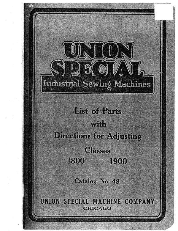
UNION
  PECIAL
Industrial Sewing Machines


        List of Parts

           with

    Directions for Adjusting

            Classes
     1800             1900


          Catalog No. 48


UNION SPECIALCHICAGOMACHINE COMPANY
View original page 1Page 3 · Read text
Supplement to

   Catalog No. 48


                     Prion Specia


                Style 1800 AA
 and Typical of Styles 1800 AC, 1800 AE,
      1800 AG, 1800 AH, 1900 AA

      PROPERTY OF
DEVELOPMENT/CATALOG DEPT.

   Please return to the Catalog Dept.

                  DEC 0 9 1992
Date received to file:
View original page 3Page 5 · Read text
Styles of Machines Covered
            by this Supplement
1800 G -For seaming medium and large bags; equipped with
             thread stand and floor treadle lifter..
1800 H - For piecing sausage casings; forged steel needle lever.
 1800 AA-For seaming medium and large bags, light and medium
              weight; forged aluminum alloy needle lever.
 1800 AC-For seaming small cotton bags; forged aluminum alloy
           needle lever.
 1800 AF-For seaming large bags; forged aluminum alloy needle
                lever, two needle double locked stitch.
 1800 AG- Equipped with thread stand and floor treadle lifter;
              otherwise same as Style 1800 AA.
 1800 AH-For piecing sausage casings; high speed type.
1900 L -Makes double locked stitch; otherwise same as 1900 M.
 1900 M -For hemming bags; forged steel needle lever, underslung
              feed rocker, chain stitch.
 1900 A1-For seaming medium and large size bags; double feed
             dog, forged aluminum alloy needle lever.
View original page 5Page 6 · Read text
Symbol Order By                 Definition                         Price

  2 A      Cloth Plate Slide, left, for Style 1900 M. ... .... .... .....  80.70
 2 CU                    right, for Style 1900 M (stop screw
              No. 150........... ...... .... ....                  .70
             Cloth Plate Guard (serew, front, No. 92 A, rear No. 92)      .35
  6 E     Looper Eccentric fork, without shoes................ ..       .90
  7 G       Feed Rocker, floating design, for Styles 1800 A, 1800 G.   2.75
  7 H      Feed Rocker Arm, for styles in Class 1800; also Style
            1900 AA (clamp screw No. 93)......                   1.50
  § A       Feed Rocker Shaft, 52% inches long, for styles in Class 1800
               also Stvie 1900 AA........ . .......                      .80
 38 V      Looper Eccentric, for Style 1900 M (spot screw No. 96)..    90
 50 D      Needle Bar, standard diameter 257 inch, for Style 1900 M
             (set screw No. 88)................ ... . .             1.60
 53 A     Needle Bar Thread Evelet (screw No. 22768)              .10
 63 A     Presser Spring, for style 1900 ........ .............      .40
 64 B                     Regulating Screw Lock Nut, for Style 1900 M    .15
 68 B       Main Shait Sleeve, 11⅙ inches long, without lug, for Styles
                 in Class 1800; also Style 1900 AA. .... . . ....             .20
  73 X     Set Serew, for looper on styles in Class 1800; also Style
           1900 AA..............................      .07
 88 A       Set Serew, for needle bar on styles in Class 1800; also Style
              1900 AA..... ... .... .......
 92 A    Screw, front, for cloth plate guara..................      .07
 194      Hand Lifter, for Styles 1800 AA, 1800 AC, 1800 AE
             1800 AG, 1800 AFI, 1900 AA (stud No. 86).              1.00
 195 X      Throat Plate, for Style 1900 AA (serew No. 87).          2.25
 197 X     Feed Dog, for Style 1900 AA (screw No. 93).              2.00
 198 X       Presser Foot, for Style 1900 AA (screw No. 88).          2.75
 267         Feed Bar Shaft Collar, for Style 1900 M (screw No. 98).      .30
 334        Tension Thread Eyelet, for Style 1900 M (screw No. 98).     .10
 419 A        Lifter Lever Extension, for Styles 1800 G, 1800 AG (screw
              No. 93A)
View original page 6Page 15 · Read text
CATALOG No. 48
    Small Arm Flat Bed
      Machines


                       Classes 1800 and 1900


             Directions for Adjusting
                  with
               List of Parts

UNION SPECIAL MACHINE COMPANY
                       General Office: 400 N. Franklin Street
                     CHICAGO, ILLINOIS
View original page 15Page 17 · Read text
IMPORTANT NOTICE TO
       CUSTOMERS


    The parts listed in this catalog are furnished

 at list prices for repairs only.

   Attention is hereby called to the fact that
many of said parts are subjects of patents,
 or enter into patented combinations, and that

 in furnishing these parts at list prices we only

 license their use for repairing machines of

 our own make, in their original condition.


   Notice is hereby given that the sale of

 such parts by the purchaser, or the use thereof

 for changing over machines from one style

to another, or for any other than bona fide
repair purposes, is an infringement, for which
the seller or user will be liable to prosecution.
View original page 17Page 19 · Read text
FOREWORD


  In Catalog No. 48 are found directions for
adjusting styles of machines in Classes 1800
and 1900, together with a list of parts for re-
pairs only. Directions for installing and
operating machines in these two classes,
however, are given with appropriate dia-
grams in a separate booklet, Catalog No.
48 A. Power Transmitter parts are listed in
Catalog No. 29; needles are comprehen-
sively described in Catalog No. 45. Copies
of any of these catalogs will be shipped
when requested.
View original page 19
Page 20 · Read text
CLASSES AND STYLES


          A machine adjusted to perform a specific operation is given

a Style Letler corresponding thereto. Specifications of the sev-

   eral standard Styles are given hereunder.


                      CLASS 1800

  Flat Bed Machines with Feed Cap. Bed 10 Inches Long, Space at

     Right of Needle 5½ Inches, Needle, Same Length as Type 143.

 STYLE

  1800 A--For seaming bags; single needle, Double Locked Stitch,
        maximum length of stitch, # inch. Presser Foot No.
          65 X, Throat Plate No. 112 X, Looper No. 26 X, and
           Feed Dog No. 22 X.

 1800 B-For seaming bags; single needle, chain stitch, maximum
         length of stitch, # inch. Presser Foot No. 65 X,
          Throat Plate No. 112 Y, Looper No. 26 Y, and Feed
        Dog No. 22 X.

  1800 C-For seaming small cotton bags; single needle, Double
        Locked Stitch, maximum length of stitch, + inch.
            Presser Foot No. 65 Y, Throat Plate No. 0112, Looper
          No. 26 X, and Feed Dog No. 22 V.

  1800 D-For seaming small cotton bags; single needle, chain
              stitch, maximum length of stitch, ‡ inch. Presser Foot
           No. 65 Y, Throat Plate No. Q112, Looper No. 26 Y, and
           Feed Dog No. 22 Y.

  1800 E--For seaming bags; double needle stitch, one under thread,
        maximum length of stitch, ‡ inch. Presser Foot No.
         65 Z, Throat Plate No. 30024 C, Looper No. 26 X, and
           Feed Dog No. 30005.

  1800 F-For sewing fringe and border to rugs; single needle Dou-
            ble Locked Stitch, maximum length of stitch, # inch.
             Presser Foot No. 1827 A, Throat Plate No. 1828, Looper
           No. 26 X, and Feed Dog No. 1826.
              6
View original page 20Page 21 · Read text
CLASSES AND STYLES


                     CLASS 1900


 Flat Bed Machines without Feed Cap. Bed 10 Inches Long, Space
  at Right of Needle 5½ Inches, Needle Same Length as Type 143.

 STYLE.
 1900 A--For seaming bags; single needle, Double Locked Stitch;
        maximum length of stitch, § inch. Presser Foot No.
         65 X, Throat Plate No. 112.X, Looper No. 26 X, and
           Feed Dog No. 22 X.

  1900 B- For seaming bags; single needle, chain stitch, maximum
         length of stitch, ‡ inch. Presser Foot No. 65 X,
          Throat Plate. No. 112 Y, Looper No. 26 Y, and Feed
         Dog No. 22 X.
1900 C--For seaming bags; double needle stitch, one under thread,
        maximum length of stitch, ‡ inch. Presser Foot No.
         65 Z, Throat Plate No. 112 Z, Looper No. 26 X, and
          Feed Dog No. 22 Z.
1900 D- For hemming bags; single needle, Double Locked Stitch.
        maximum length of stitch, ‡ inch. Presser Foot No.
        1920 D, Throat Plate No. 1924 E, Looper. No. 26 X,
         Top Feed Mechanism, and Feed Dog No. 1905 D.
 1900 F-For hemming bags; single needle, Double Locked Stitch,
       Maximum length of stitch, ‡ inch. Presser Foot No.
         65 X, Throat Plate No. 1924, Looper No. 26 X; and
          Feed Dog No. 1905 D.
1900 G-For hemming bags; single needle, chain stitch, maximum
          length of>stitch, ‡ inch. Presser Foot No. 65 X,
         Throat Plate No. 1924, Looper No. 1908, and Feed Dog
         No. 1905 D.
View original page 21Page 24 · Read text
ADJUSTING MACHINES IN CLASSES
             1800 AND 1900

     Machines of Styles 1800 A and 1900 A embody principles, most
  of which are common to other styles in Classes 1800 and 1900.
 These two styles, therefore, are given consideration in detail.
  Peculiarities of other styles are taken up thereafter.
     In order to make possible speed with quality of workmanship,
 Union Special Sewing Machines have been made susceptible of
 various adjustments. Use will soon show that kind of adjustment
 best suited to sewing rapidly and neatly goods of a particular
  quality.

 Machine Pulley Direction The direction in which ma-
 of Operation                   chine pulleys of machines of                                   Classes 1800 and 1900 are
 to be operated is indicated by an arrow on the threading diagram.
 Whenever a machine pulley is operated by hand, the same direction
 of turning should be followed. To turn in one direction soon be-
 comes a habit and does away with a source of confusion possible to
 one attempting to adjust a machine or to bring its moving parts
in time with one another..

 Useful Hints A machine "out of order" should not have
                  its adjustment changed until the following
 sources of trouble have been investigated:

     1. Is the machine threaded according to directions? especially
at the tensions? Remove any lint which may have gathered be-
 tween the tensions. Check the amount of tension in the case of
 each thread.

     2. Is the needle up in the needle bar as far as it will go? Is
 its spotted side away from the operator? Is the longer groove.
 facing the operator?

     3. Is the needle straight? Test this by rolling its shank on

 a flat surface and watching the needle point. If the needle point
wobbles, get another needle.

    4. Inspect the needle hole in the throat plate. It may have
become roughened so that it cuts the thread. If it proves to be
rough, smooth it with a narrow strip of emery cloth.

    5. Roughened or grooved eyelets, take-up wire, tension posts
or tension discs may cut the thread. Smooth them with emery or

crocus cloth or replace entirely.

                   10
View original page 24Page 25 · Read text
ADIUSTMENT

     6. Clean and oil the machine thoroughly. Try a new needle
 and re-thread the machine.

     7. If the style of machine under consideration is fitted with a

  loop retainer, examine it. If it is bent or roughened, repair or re-

  place it.

      8. If this procedure does not bring results, then consider the
 adjustment.
Caution Do not neglect after a change to test the operation
              of a machine by hand before applying the power.
 By following this rule there is no likelihood of breakages.

 Point of View in      In describing the positions or move-

Descriptive Matter ments thereof partsis buthereafterone point ofconsidered,view used;
 it is that of an operator in position ready to operate the machine
 concerned.


     ADJUSTING STYLES 1800 A AND 1900 A


Double Locked Stitch Wain make Sty single raw and
 Double Locked Stitches. In the forming of this stitch, two thread
 carrying parts known as the "needle" and the "looper," are em-
 ployed. There are three steps in the forming of the stitch as follows:


                 FIGURE 2    FIGURE 3  FIGURE I
                    11
View original page 25Page 26 · Read text
ADIUSTMENT

      1. When the machine is set in operation, the needle carries its
 thread down through the fabric, and as it begins to ascend, it

 throws to the rear a loop of thread which the looper moving from

 right to left enters. See Figure 1.
    2. While the needle is above the throat plate, the feed dog
 moves the fabric forward away from the operator, the looper rocks
 toward the operator across the path of the needle, changes direc
 tion, and moves toward its right-hand position. A glance at Fig-
 ure 2 will show that in this series of movements there has been
 formed a space triangular in shape, bounded by the looper thread

 on the left, the needle thread on the right and the farther side of
 the looper. Into this space, the needle descends with its thread.
     3. Continuing its movement toward the right-hand position,
 the looper leaves the stitch on the needle. See Figure 3.
    As the needle again ascends, the stitch is released from the nee-

 dle and is tightened in the fabric by the looper as it forms the fol-

lowing stitch.


Timing Looper with Needle necessary in order to bring
 the looper in time with the needle. They are to be made in the

 order given.

     First Adjustment: The needle bar is in time with the looper

 when, with the needle bar in its lowest position, the point of the

 looper is h inch from the center of the needle. With a variation

 in this spacing, there is also a variation in the size and form at-
 tained by the loop of thread behind the needle when the looper
point is about to enter. This if inch adjustment may be obtained
 by following in their order the seven steps which follow:
    1. Insert a new needle before attempting this adjustment.
     2. Loosen the two nuts locking the looper connecting rod by.
turning them away from the operator.

     3. Turn the machine pulley by hand until the needle bar has

 reached its lowest point.

                             4. Now hold the in inch gauge, No.
                          21225, in the left hand, with its V
                          straddling the needle and the wider
                        part of the edge, indicated by a
   221225          dotted line in the illustration, to the
                                  right.
                     12
View original page 26Page 27 · Read text
ADJUSTMENT

     5. Exercising care to hold the gauge in a horizontal position,

 turn the looper connecting rod until the point of the looper just
 touches the edge of the gauge.
     6. Set aside the gauge; continue turning the machine pulley
 until the long, straight edge of the take-up is vertical and facing
 the operator; or turn the machine pulley until the point of the
 looper has passed to a position about * inch to the left of the path
of the needle.
     7. Tighten first the right-hand locking nut and then the left-
 hand locking nut on the looper connecting rod, and while so doing,
 manipulate the bearings over the balls so that with the nuts drawn
 up tight, the bearings still move over the balls freely.
     8. Apply the gauge to make sure that the adjustment has not
 been altered.
    Second Adjustment: To set the needle eye in height with ref-
 erence to the path of the looper, turn the machine pulley in the
 direction the machine runs until the looper point moving from right
 to left is even with the left side of the needle. Loosen the two nee-
 dle bar set screws and move the needle bar until the upper edge of
 the needle eye is approximately 2 inch below the under side of the
 looper. Tighten the set screws.
    Third Adjustment: When the looper passes behind the needle
 to enter the loop of thread formed by the needle, the looper point
 should just clear the needle. To obtain the clearance desired, four
 steps will be found convenient, as follows:
         1. Loosen the two set screws binding the looper eccentric
 fork to the looper rock shaft.
    2. Turn the machine pulley until the looper point is opposite
 the left side of the needle.
    3. Move the looper away from the needle until daylight may
 be seen between the needle and the looper. A piece of white paper
 used as a background will aid in securing a spacing which in prac-
tice varies from a few thousandths of an inch to to inch. The
 thickness of three plies of newspaper is about     , inch
     4. Maintaining the spacing secured in item No. 3, tighten both
 the upper and the lower set screws binding the looper eccentric
 fork to its shaft.
     In machines of this style, a needle Type 143 is generally used.
The rear portion of needles of this type is cut away for a short dis-
 tance above the eye, so that the looper may be set quite close to the
 center of the needle.

                     13
View original page 27Page 28 · Read text
ADJUSTMENT
                   About the middle of the main shaft are lo- Take-up and
 Cast-off Wire cated the take-up, the cast-off wire and the                     take-up thread eyelet, which, during the
 forming of the stitch, hold the looper thread taut until the descend-
  ing needle point has entered the triangle of thread shown in Fig-
 ure 2, and, then, release the looper thread for the forming of the
 following stitch. A simple test to determine whether they are in
 adjustment can be made as follows: Take hold of the looper thread
 on the left side of the take-up thread eyelet, draw it slowly through
 the eyelet, and while so doing, turn the machine pulley in the direc
 tion the machine runs, until the thread moves from the long
 straight edge of the take up to the circular edge. Stop at this
 point. Observation will show the needle point to be about even
 with the lower edge of the looper. In fact, a variation of st of an
 inch from this position will be found in machines correctly ad-
 justed.
    The arms of the take-up thread eyelet, which project over the
 main shaft, are adjusted to clear the main shaft sleeves. To change
 the height of the arms, change the height of the screw on the left
 side of the take-up frame supporting them.
                   If it is desired to have a machine adjusted to form

Feedtime toDogfeeda chainthe fabricof stitchesadequately,betweenit is necessarybags andtoatsetthethesamefeed
 dog so that its two teeth farthest from the operator project above
 the surface of the throat plate about half their height.
   To change the height of the feed dog, remove it and change
 the height of the screw supporting it.
    Observation of the throat plate will show that its surface is
 inclined and that the end farther from the operator is the higher
one.

Presser Spring  Extending along the top of the frame of the
                   machine is found a presser spring for the
purpose of maintaining pressure on the presser foot. A ""
screw furnishes a means of applying considerable pressure.
           Tension may be applied to both needle and looper
Tension threads by means of tension nuts. The tensions nost
conducive to speed and quality vary with particular fabrics and
threads, and must therefore be determined by actual trial. In
practice, however, the tension applied to the looper thread is less
than that applied to the needle thread, and the tension usually ap-

                     14
View original page 28Page 29 · Read text
ADJUSTMENT
 plied to the latter is such as to fall just short of the breaking
  strength of the thread.
    Too much tension on the needle thread will result in breaking
 of threads, in puckering of fabrics, and in shortening of stitches.
 Applied to the looper thread, too great a tension will cause break-
 ing of threads and will prevent chaining.
    Too little tension applied to the needle thread will result in
 loose and irregular stitches on the under side of the fabric; threads
 will be broken, stitches will be skipped and chaining out prevented.
 Too little tension put upon the looper thread will cause stitches to
be skipped.
       ADJUSTING STYLES 1800 B AND 1900 B
    Much of the adjustment material already taken up and apply-
 ing to Styles 1800 A and 1900 A has application to Styles 1800 B
 and 1900 B also. Additional matter having special application to
 Styles 1800 B and 1900 B is given consideration hereunder.
Chain StitchMachines of these two styles, 1800 B and
              1900 B, make a row of chain stitches. Acting
 directly upon a single thread to form this stitch are three parts, a
 needle (the sole thread carrying part), a looper, and a loop re-
 tainer. The loop retainer is located on the under side of the throat
 plate.


     FIGURE:          FIGURE 5          FIGURE 6
                     15
View original page 29Page 30 · Read text
ADIUSTMENT

     There are several steps in the forming of the single-thread
 chain stitch, as follows
     1. Set in motion, the needle carries its thread down through
 the fabric, and as it ascends, it throws a loop of thread to the rear,
which the looper moving from right to left enters. This is indi-

 cated in Figure 4.
     2. While the needle is above the throat plate, the feed dog
 moves the fabric forward away from the operator; the looper rocks
 toward the operator across the path of the needle, changes direc-
 tion, and starts toward the right. This step is not illustrated.
     3. As the looper continues its movement toward the right, it-
 carries with it the lower portion of the loop of thread. During this
 movement, the near strand of the loop of thread catches on the
 prong of the loop retainer, while the farther end of the loop is held
 by the fabric. Acted upon in this manner, the loop of thread is
 drawn toward a horizontal position and thus held until the re-
 descending needle enters it. This is the situation shown in Figure
 5. The loop retainer is not indicated.
     4. Continuing its movement to the right, the looper releases
 itself from the stitch, which is now on the needle, as shown in
 Figure 6.
    As the needle re-ascends, it withdraws from the stitch, and the
 subsequent movements of both the needle and the looper tighten
 the stitch in the fabric.

 Adjusting Needle, Looper In order to bring the parts
                                forming the chain stitch in
 and Loop Retainer          time one with the other, six
 adjustments are necessary. They must be made in the order
listed.
      First Adiustment: This adjustment is the same as the First
 Adjustment described for Style 1800 A.
    Second Adjustment: This adjustment is the same as the Sec-
 ond Adjustment described for Style 1800 A.
     Third Adjustment: This adjustment is the same as the Third
 Adjustment described for Style 1800 A.
     Fourth Adiustment: Turn the machine pulley in the direction
 the machine runs until the looper moving from right to left reaches
 a position such that the deepest point in the right end of the notch
 in the looper is opposite the prong of the loop retainer. Here stop
                    16
View original page 30Page 31 · Read text
ADJUSTMENT

     and set the loop retainer so that between the prong of the loop re-

     tainer and the looper there is just enough space for the passage of

     the largest thread to be used. If this space is made too large, how-

     ever, the prong of the loop retainer will not project sufficiently to

     engage the loop of thread when the latter is carried by the looper
     toward the right.


        Fifth Adjustment: When the looper moves from left to right,

     the upper edge of it should just clear the prong of the loop retainer.

       A clearance of two thicknesses of newspaper is sufficient. This
    spacing may be secured by altering the height of the looper by
    means of a collar No. 21210 on the looper shank and by slightly
    bending the loop retainer if necessary.
        Sixth Adjustment: Between the right side of the loop retainer
   prong and the feed dog there must also be sufficient space for the
   passage of the heaviest thread used.

                   STYLE 1800 C
                   This machine, which makes the Double Locked

   facilitate the turning of sharp corners, the surface of the presser  footDescriptionhas been reduced.Stitch, is designed to seam small pockets. To
    A Type 143 Size 067 Needle is the largest that can be used
  without enlarging the throat plate needle hole.
    A 3-ply twine is the size ordinarily used in both the needle and
  the looper for sewing small pockets.
 Adjustment  With the needle bar in its lowest position, the
                   point of the looper is brought by means of a
  gauge 3 inch from the center of the needle. Follow the method
  outlined for Style 1800 A. This machine may be adjusted, in other
  particulars also, according to directions given for Style 1800 A.


                   STYLE 1800 D


Descriptionfacilitate the turningMachineof sharpis Stelecorners,nest itseamis providedinhal pockets.with a presseraNd
 foot, the surface of which has been reduced.
   A Type 143 Size 067 Needle is the largest which can be used
without enlarging the needle hole of the throat plate provided.
    For sewing small pockets, a 3-ply twine is frequently used.
                       17
View original page 31Page 32 · Read text
ADIUSTMENT

                    Directions for adjusting machine Style 1800 B,
Adjustment as well as directions for Style 1800 A, may be
followed in adjusting Style 1800 D with the exception of the looper
 gauge specified. A looper gauge of ? inch should be used.

         ADJUSTING STYLES 1800 E AND 1900 C

     Machines of Styles 1800 E and 1900 C are designed to sew bags

 that require great strength of seam.

 The Stitch In the forming of the double thread stitch, two
                  needle threads, together with a looper thread, be-

 come a part of the stitch. There are three steps in the forming of-
the stitch as follows:

     1. When the machine is set in operation, the needles carry
 their threads down through the fabric and as they ascend, throw
 to the rear loops of thread, which the looper moving from right to
left enters.
     2. While the needles are above the throat plate, the feed dog
 moves the fabric forward, away from the operator, the looper rocks
 toward the operator across the path of the needle, changes direc-
 tion and moves toward its right-hand position. In this series of
 movements, there has been formed a space triangular in shape,
 bounded by the looper thread on the left, the two needle threads

 on the right, and the farther side of the looper. Into this space the
needles descend with their threads.

     3. Continuing its movement toward the right-hand position,

 the looper leaves the stitch on the needles.

     As the needles again ascend, the stitch is released from the

 needles and is tightened in the fabric by the looper as it forms the

 following stitch. Except, then, for the fact that the stitch is made

 of three threads instead of two, it is formed in much the same man-

 ner as the Double Locked Stitch.

Timing Looper with Needle Win wee bar when, with
 the needle bar at its lowest point, the point of the looper is a
 inch from the center of the needle located in the center of the nee-
dle bar. Steps to secure this timing may be followed as given for
Style 1800 A with the exception of the gauge.
   To set the needle bar correctly, proceed as follows:

     1. Turn the needle bar so that one of the two screws at the

                     18
View original page 32Page 33 · Read text
ADJUSTMENT

   lower extremity of the needle bar for clamping the needles extends

   toward the right and the other extends toward the rear, away from
   the operator.
       2. Turn the machine pulley until the point of the looper is
 even with the left side of the left needle. Turn the needle bar
   slightly until the needles in line are parallel with the front or near
  side of the looper.

      3. Now move the needle bar vertically until the entire eye of
  the left needle appears below the underside of the looper.

      The means of adjustment just outlined, it will be noted, fol-
  low closely the principles laid down in the case of the Style 1800 A.
      Observation of the two needles in position will show that the
   left needle is so seated that it extends slightly below the right nee-
  dle. With such a seating, the looper enters each loop of needle
  thread at the moment best suited in each case.
            Type 143 Size 080 needles are used in these two styles
 Needles of machines, because the blade and these two styles
 the same diameter.
                              Near the upper end of the nee-
 Needleof these Threadtwo stylesTake-upa needle alethreadbartake-upis foundwire.onInmachinesthreading,
  cause the two needle threads to pass above this wire. This take-up
  counteracts the elasticity of the twine and aids in forming a steady
  loop.

               MACHINE STYLE 1800 F

     The information given hereunder and applying to the Machine

 Style 1800 F is complete therefor only when read as supplementary
 to descriptive matter given heretofore under Style 1800 A.
 Use This machine, which makes the Double Locked Stitch, is
        designed to sew fringe and border to rugs. Its presser foot
 is provided with a pilot to open the pile, which, returning to. its
 original condition after passing the presser foot, conceals the
stitches.

     By replacing presser foot No. 1827 A with presser foot No.
 65 X, an added variety of operations in the manufacture of rugs
 and carpets is made possible.
                  Attached to the take-up frame in Style
Nipper Springs 1800 F is a pair of nipper springs which, by
 clamping the supply of looper thread at the right of the take-up

 while the looper is moving to the right, oblige the take-up to take

                        19
View original page 33Page 34 · Read text
ADJUSTMENT

 thread at the left of the take-up and in so doing to remove the slack.

These springs should begin to tighten as soon as the looper from

 its extreme left position has moved about s inch to the right. The
combined tension applied by the tension discs and the nipper
 springs when the latter are exerting their maximum, should be
 just within the breaking strength of the thread.
   A change can be brought about both in the amount of tension
  and in the duration of the tension by:
     1. Changing the height of the screw in the lug of the looper
 rocker frame, which intermittently compresses the nipper springs;
     2. Or slightly bending the upper nipper spring.

Adiustment Thewithncedlethe barneedleis inbartimeat itswithlowestthe looperposition,when,the
 point of the looper is 3 inch from the center of the needle. Steps
 to secure this adiustment may be followed as given for Style
 1800 A, with the exception of the gauge.

                   STYLE 1900 D
    The information given hereunder and applying to the Machine
 Style 1900 D is complete therefor only when read as supplementary
 to descriptive matter given heretofore under Style 1800 A.
        This machine forms Double Locked Stitches up to half an
 Use inch in length. It is provided with an upper feed as well
 as a lower feed, adjusted and synchronized the one with the other,
 so that the feeding of two or more plies of fabric is readily accom-
 plished. The machine is suited to a variety of operations in the
 seaming of bags.

Timing Looper with Needle Win reelboper when with
 the needle bar at its lowest point, the point of the looper is 3
 inch from the center of the needle. Steps to secure this timing
 may be followed as given for Style 1800 A, with the exception of
 the gauge.

                   STYLE 1900 F
 UseThe1900informationF is completegiventhereforhereunderonly whenandreadapplyingas supplement-to Style
 ary to descriptive matter given heretofore under Style 1800 A.
     This machine forms Double Locked Stitches up to half an inch
 in length. It is suited to hemming bags for which a long stitch is
  required.
                      20
View original page 34Related documents and language editions
From the ISMACS International. Original publisher and archive notices are retained.
Check the model and edition against your equipment.
PDF verified 2026-10-11.