Sewing catalogs & reference
Union Special 1800 & 1900 Models — Product catalog
Product catalog for Union Special 1800 & 1900 Models. 16 pages in English. Read the original PDF, download or print a copy without registration.
16 pagesEnglish1.1 MB PDF
Loading your manual…Open PDF directly
Document details
- Brand
- Union Special
- Model / document
- Union Special 1800 & 1900 Models
- Document type
- Product catalog
- Language
- English
- Pages
- 16
- File size
- 1.1 MB
- Category
- Sewing catalogs & reference
- Document date
- Not specified in catalog
Search available document text
Find a term, then jump to its page in the original PDF. Image-only pages may not be searchable; check the PDF for exact wording and diagrams.
Page 1 · Read text
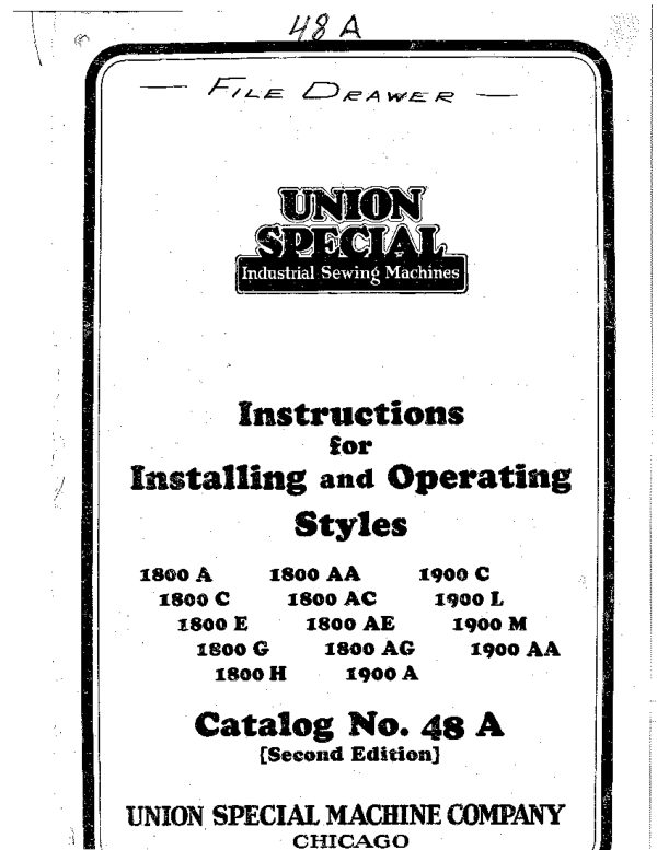
18 A

   FiLE DeawER

    UNION
    SPECIAL
            Industrial Sewing Machiries


       Instructions
         for
Installing and Operating

         Styles

 1800 A   1800 AA    1900 C
  1800 C   1800 AC     1900 L
   1800 E   1800 AE   1900 M
     1800 G   1800 AG   1900 AA
      1800 H   1900 A

    Catalog No. 48 A
            [Second Edition]


UNION SPECIAL MACHINE COMPANY
         •CHICAGO
View original page 1Page 2 · Read text
DEVELOPMENTICATALOG DEBT
       Pleese intura to the Catalog Dept
            DEC 09 1992    Date received to file::
    FOREWORD
       IT is our constanl aim lo furnish carefully pre-
        pared information that will cable the cas-
         tomer to secure all posaible economies and ad-
 vantages accruing from the use of Union Specials.

    In the pages which follow, detail instructions are
 given for installing and operating the styles of machines
 covered by this catalog.


    Instructions for adjusting and repairing these Ina-

          chines, together with illusttations and definitions of the

 parts and the needles used, are found in Catalog No. 48.

 Information relative to the transmitter is contained in

 Catalog No. 29. Needles are listed and fully described

 in Catalog No. 15. These catalogs will be furnished
 gratis, on rcquest.


    In line with our established policy of service, our

 Sales Foginecring Department has compiled complete

 data relating to sewing room layouts, sequence of op-

erations, average hourly productions, and up-lo-dato
 equipment used in the manufacture of all scwed articles.
 All this intormation, the result of research involving
great expense, the Company now offers its customers
 and prospective customers alike. Our engincers will be
 glad to assist in solving your sewing problems.

   The one dominating idea back of "Union Special'
 is to huild the best industrial sewing machines in the
 world. The name is a synonym for "Superlative Ex-
 cellence, 73
               Union Special Machine Company.
View original page 2Page 3 · Read text
: a


                                           Specie


            Style 1800 Ad and Typical of Style 1800 A0, 1500 AM, ISOO A0 B7 1900 12
         FAST
          STURDY
                 ACCURATE
                      RELIABLE

            They are the latest improved high speed machines and the last word
             in bag sewing cquipment.
                            Style Numbers and Defuitions
         A machine equipped with specific parts and fitted for a specifio opera-
             tion is given a style number, the symbol for which is a number evenly divisi-
           ble by 100, with one or more. letters suffsed. Esample: "1800 Ad."
                            Classes 1800 and 1900

          Flat Bed Machines, for Bags and Miscellaneous Work, Long Needles,
               Bed 10 Inches Long, 5½ Inch Space to Right of Needle Bat


           1800 A--For seaming medium and large bags, light and medium weights,
                      forged steel needle lever, short cloth plate, one needle double
                     locked stitch Type. 401, maximum length ⅓ inch, Type 143
                         ncedle.
View original page 3Page 4 · Read text
Classes 1800 and 1900

1800 C   For seaming small cotton bags; forged steel needle lever, short
               cloth plate, one needle double locked stitch Type 401, maxi
         mum leugth ¼ inch, Type 143 needle.
1800 E   -For semming large bags; forged steel needle lever, short cloth
                plate, two needle double locked slitch Type 402, maximum
              length 1/9 inch, Type 113 needles.
1800 (7   -Equipped with thread staud and foor treadle lifter, otherwise
                   , samo as Style 1800 A
1800 II -For piecing sausage casings, forged steel ncedle lever, one needle
             double locked stitch Type 101, Type 140 needle.
 1800 AA. For seaming medium and large bags, light and medium weights,
              forged aluminun alloy needle lever, one needle double locked
               stitch Type 401, maximum length ⅓ inch, Type 143 needle
              This is one of the latest improved machines, built on an estra.
            heavy bed with all moving parts of the lightest construction
               possible.
 1800 AC- For scaming small cotton bags; forged aluminum alloy needle
              lever, one needle double locked stitch Type 401, moximum
              length ¼ inch, Twme 143 needlc. This is one of the latest
              improved machines, built on an extra heavy bed, with all
            muving parts of the lightest construction possible
 1800 AE-Hor seaming large bags, forged aluminum alloy needle lever, two
            ncedle double locked stitch Type 402, maximum lenglh ⅓
               inch, Type 113 needles. This is one of the latest improved
              wachines, buill on an extra heavy bed, with all moving parts

                 of the lightest construction possible.:

  1800 AG-Equipped with Uhread stand and floor treadle litter, otherwise
              same as Style 1800 AA.
 1900 A   -For seaming medium and large bags, light and medium weights,
                forged steel needle lover, long cloth plate, double feed dog,
              one needle double locked stitch Type 101, maximum length
               I fact, Typc 148 needle.

                1900 C • For scaming large bags, forged steel needle lever, long cloth
              plate, two needle double locked stitch Type 402, maximan
               length ⅓ inch, Type 113 needles
 1900 L -For hemming bugs; forged steel needle lever, underalung feed
             rocker, double locked stitch Typo 101, masimum length of
               stitch ¾ inch, Type 143 needle. Standard equipment includes
               two hemmers; unc for cotton and the other for jute.
  1900 M -For hemming baga; forged sleel needle lever, underalung feed
               rocker, chain stitch Type 101, maximum length of stitch ¾
             inch, Type 143 needle. Standard equipment includes two
             hemmers, oue for cotton and the other for jute.
 1000 AA-For seuming medium and large size bags, light and medium
           weights; forged aluminam alluy needle lever, long cloth
                plate, double feed dog, one needle double locked stitch Type
              401, maximom length ¼ inch, Type I48 needle. This is one
                of the latest improved machincs, built on an extra heavy bed
                with all moving parts of the lightest construction possible.
View original page 4Page 5 · Read text
T.


                                             Style 1800 4 Plan of Instalbration
                    The installation of other styles linded in this catalog is appronimalady the sure.
View original page 5Page 6 · Read text
Installing


 General Plan
   The diagram on the preceding page shows the general plan of installa-
 tim to be followed, also the dircetion the machino runs

 Ready to Operate
    Refore shipment, each machine is thoroughly run in, accurately sud-
 juated and carefully inspected. This is evidenced by the test sample left in
 the machine. Packed by killed hands, they arrive at their destination

 ready for service

Caution

   Carefully note the threading of the machine when laker from the ship-

 ping box. Do not withdraw the threads. 'The operator can use the thread

 advantageously by tying the ends and drawing the new thread in the ma-

         chine. It will do no harm to torn the machine puller onc or two revolt-
 tions, provided it is turned in the indicated direction

Power Tables
    In the manufacture of bags for which most of the styles in Classes 1800
 and 1000 are designed, the maximum of efficieney can only be seeured by
 installing the machines on specially built tables. We are prepared to fur-
 nish a bluc print, No. $3822 Q, which will cable a local carpenter to
 construct economically a table of the most approved design. An ideal table
 for a small factory can be had in our portable individual power lable No.
 21871 AL; which is equipped with an clectric motor.

 Pulley Diameters
   Working diamelers of the varions pullcys arc: Machine pulley, 2½
 inches; transmitter driving pulley, 7 inches; transmitter driven pulley,
small come, 8%4 inches, large cone, 5¾ inches. Line shaft pulleys are made
in diameters of 6, 8, 9, 10, 11, 12, 13, 1 and 16 inches.They are 1½ inch
 face and If inch bore.

Speed
   The following table gives the speed recommended for each style when
used for the operation mentioned in the machine definition
         Sirle           Revolutions          Style            Revolutions
       Number      Per Min.          Number       Per Min.
       1800 A      3000           1800 A,     3500
       1800 C       3000            1800 AG     3500
       1800 E       3000            1900 A      3000
       1800 G      3000            1900 C      8000
       1800 II      2500           1900 I       2600
        1800'AA      3500            1900 M      2500
      1800 AC     3500             1900 AA     3500
View original page 6Page 7 · Read text
Installing

    'To find the speed of the sewing machine pulley D (sec illustration)
when the diameters .of pulleys A, B, C, and I and speed of Pulley A are
 known, allowing 6% for the invitable belt slippage:


                                 Rule:. Divide the wroduet of the diant-
                                ders of driving madleys (1 0 C) of the
                                  groduct of the diameters of driven, pile
                                bey: (B a D) und maltiply the quotient
                         by the speed of bine shaft putty d and
                            94%


Example:
  12 inches = Diameter lie shaft pulley A (Driving Pulley).
       inches   = Diameler transmitter pulley & (Driving Pulley).
  3¾ inches = Diacter transmitter pulley B (Driven Pulley).
  9½ inches -Diameter sewing machine pulley D (Driven Pulley):
 450 R. P.M.= Speed. of line shaft pulley A.
 94%         = Belt cficiency (6% allowed for alippage).
   Then the speed of the swing machine is:
             11 TY
             3%121 $450%. U1 = 3171 B. P. M.
   The Order Department endeavors to send the most suitable diameter line
shaft pulley with each machine. A possible missing factor is the speed of
the customer's line shaft. As the driven pulley on the transmitter is de-
signed with a small and a large cone, two different speeds can be secured
on the sewing machine with a given diameter of line shaft pally. by, ar-

ranging the lat belt accordingly. The formula furnished will be helpful

in deciding which come to use to secure the desired speed
Spacing of Machines
   The customary spacing measured from needle to needle is 48 inches,

which is ample to prevent average size bags from being entangled with the

belt of the adjoining machine.
View original page 7Page 8 · Read text
Installing


   Machine and Transmitter

       Set the machine on the table in the approsimate position it is desired
    to have it occupy, with its pulley toward the right and the front edge of:
    the cloth plate one inch back of and parallel to the front of the table,.
         If an iron base plate is included in the equipment, it should be placed
   under the machine so that the hole near the center of the base plate reg-
    isters with the tapped hole in the bed of the machinc. Directly below the
    hole near the center of the base plate, bore a 1 inch hole in the table. Pass
              the "T' serew through the hole and fasten the machine to the base plate.
  Move the hase plate so that the "I"' screw centers in the bole in the table.
   Remove the machine and fasten the base plale to the table.
        If an iron base plate is not included in the equipment, bore a it inch
    hole directly below the tapped hole in the bed of the machine and fasten
    the machine to the table with the thumbscrew provided for the purpose.

       To avoid contacl with the opcrator's clothing, the transmitter should be
    fastened to the underside of the table as far back as possible and the groove
    in the brake pulley should be in line with the groove in the machine pulley.
  An excollent plan is to place the transmitter on top of the table so these
    two pulley grooves are in line and mark the table under the front right hole
    in the transmitter plate. Bore a ¼ inch hole at the mark, or directly in
   front of it a sufficient distance to avoid the plale extending beyond the

   rearhole edgeand fastenof thethetable.transmitlerPass thewith¼ inchthe bolt,flat headwhichstoveis sufficientholt throughto holdtheit
     tcroporarily.
       Place the pulley on the line shaft in line with the step of the trausmitter
   Loose pulley it has been decided to use, and tighten it so that it binds but
   remains suscoptible of movement by hand, Swing the frame of the trans-
    mitter (which is pivoted to its hase plate) toward the line shatt approxi-

   matelyscrew andfifteentightoningdegreesthefromfronttheregulatingvertical. byscrew.lonseningThis willthe providerear regulatinga com-
   ventent take-up for the fat bell and permit the tension lo be regulated as
    desired. It is prefcrable to cross the round belt if the rotation of the line
   shaft makes it necossary. Measure the length of flat belt required and
    join the ends by driving in a malleable iron belt fastener No. 31850 against
    the transmitter pulley. See that the teeth are well clinched and that the
   fastener conforms to the curvature of the pulley. Tuen the pulleys by hand
    and swing the transmitter so the belt runs true. Place 14 inch wood
    screws in the three remaining holes in the transmilter plate and securely

    tighten the pulley on the line shaft.

        Borc one inch holes at the required angle for the round bell and locate
    them so that the take-up for the flat belt can be used. 'The dress guard
    should be fastened to the wnder side of the table directly in front of the
    transmitter pulleya.
      Locate the transmitter treadle so its center is directly under the ncedle
    with the pitman adjustment and enclosed bearing of the trcadle rest to
   the left. Variations in the treadle Incation and its incline can he made to
    suit the operator's convenience. The pitman need not necessarily hang in
    a vertical position.
View original page 8Page 9 · Read text
Installing

 Floor Treadle Lifter
    Included with some machines is a foor treadle lifter, consisting of a
 mall treadle and chain, which connects with a lifter lever attached to the
 rear of the machine. Bore a 16 inch hole through the table directly under
 the hole in the right end of the lifter lever. Looate the small treadle
 directly to the right of the transmitter treadle. Pass the chain through
 the holc in the table, connect the upper end with the lifter lever and the
 lower end with the small treadle. Adjust the incline of the latter so that
 the front end is slightly higher than the transmilter treadle.

 Thread Stand

     Included with some machines is a thread stand for holding the spooks
 or comes in a convenient position while the machine is sewing. It should
 he located behind the machine pulley and a short distance to the right.
                           Opetating
 Simplicity

    Inexperienced operators quickly adayt themselves to Union Specials,
 Obviously, practice will increase proficiency in oiling and threading the
 machine, and in haudling the work
      32
          31-


                                                        - 26
                                          --25
                            25 24


    20 19 18 12
Threading and oiling diagram for Styles 1800 4, 1800 0, 1800 M, 1800 G, 1800 E
1800 A, 1900 0, 1900 I, 1900 M.The oiling places for Styles 1800 Ad, 1600 AC,
          1600 4E, 1800 AC and 1000 Ad ure subslerbially the yome
Oiling
   Union Specials, like all precision machinery, are closely fitted, therefore,
 it is very important that all bearings are properly lubricated at frequent
 intervals. It is reconcoded that these machines be given a thorough
View original page 9Page 10 · Read text
Operating

Oiling--Continued
oiling five times a day.Any of the following brands of oil will fill the
requirements:
              Viscusity Oil Company's "Vertex"
          Vacuum Oil Company' "Gargoyle Mobiloil I'
           The Texaco Company's "'exaco Alcaid"
            Standard Oil Company's "Polarine Medium?'

    The diagram shows the places to be oiled. This sequence once men-
 urised can be followed in a surprisingly short time without the possibility
 of missing any places. All oiling places can be reached without removing

the cloth plate.

    Special allention is direcled to the upper bearing of the needle lever
connecting rod and left end of the ncedle lever where bull valves are located.
 They are oiled by pressing the ball with the oil-can spout. Styles 1800 Ad,
1800 AC, 1800 AE, 1800 ACt and 1900 AA are fitted with a signal stop oil
 cup for the right main shaft hearing. The flow of oil can be regulated by
 turning the knurled portion of the stem. Toming it clockwise redaces the
 flow and counter-cluckwise acts the reversc. Care should be taken to arid
 turning it ton far in either direction as the signal stop feature will be mulli.
fied.The flow is shat off completely when the top of the stem is toppled
 over and resumes in the same volume when the top is returned to a vertical
 position. Always discontinue the flow when the machine is not in opera-
 ton. Refilling the cup can be accomplished through convenient openings,
 which are covered by a plate to keep out the dirt and other foreign sub-

stances.

    The transmitter is lubricated with solid oil through a hollow shaft trom
 a compression eup, which should be screwed up abont once a week.

be screwed up immediately. Refilling will nol be required oftener than
 once a month. No. 3 Arctic Cup Grease, or its cquivalent in consistency,

 will fill the requirements.

Cleaning

    Accumulated Iint and dust quickly absorb the oil, which makes it neces-
 sary to kcep the machine as elean as possible. The cloth plate should be
 removed cach day and the machine given a thorongh cleaning. Remove
 the lint from the oil holes and feed dog slots.

Threading

  Styles 1800 A, 1800 0, 1800 G, 1800 H, 1800 AA, 1800 AC, 1800 ACT,
 1900 A, 1900 C, 1900 L and 1900 AA are threaded as shown in the diagram.
 Stylc 1900 MI is also threaded as shown in the disgram with the exception
of the looper thread, which is missing. Styles 1800 E, 1800 AE and 1900 C
use two needle threads and one looper thread, which pass into the machine
in substantially the same manner as shown in the diagram. Do not pass
any thread entirely around a tension post. The eyelet, adjacent to the
looper thread take-up, is hinged and its front end can be raised for con-
venience in threading. A thread hook No. 118 is furnished for drawing
 the thread under the cloth plate
View original page 10Page 11 · Read text
Operating


  Setting the Needles
     'They have two grooves; a short groove terminating in a spot milled out
  just above the eye or extending from the shank to a point about ⅛ inch
 above the eye. The opposite side has a long groove extending from the
 shank to the eve. Insert the needle as far up into the needle bar as it will
 go, with the long groove in front, so that the eye of the needle will be in
 line with the dircetion of the stitches. Then tighten the needle clamp nut
 or set seiCH.
 To Commence Sewing
   There should be about two and one-half inches of thread berond the
 eves of the needles and looper before commencing to sew.. Carry the threads
 to the rear. To start the machine, press the for edge of the treadle. When
 the pressure is released, the machine is antomatically stopped.To in~
  slantly stop the machine, apply pressure with the heel to the near edge of
 the treadle.
 Removing the Work
    Should it be desirable to remove the work without ring off, turn the
 pollcy in the operating direction wntil the needle bar reaches its highest
 position.Draw a reasonable quantity of needle thread through the tension,
  raise the presser foot, pass a pair of scissors under it and eut the necdle
 thread as elose to the upper surtace of the fabric as possible. The work
 can be removed by drawing it toward the rear of the cloth plate. In this
 manner the eut ends of the ncedle threads will be drawn to the underside
 of the material and automstically tied.


 Jute Bags double edge folder No. 28153 C is somotimos used for turning back
 the two cut edges, This folder is pivoled so that it ean be swung out of
 position when the operator uniles selvage edges. It is not ineluded as
 standard cquipment with any style.

 Bleached Cotton Bags

    Though the adjustment of the machine be perfect for other fabrics,
 some diffculty may he experienced in properly fooding bags made from
 bleached cotton fabric, duc to the filler which it contains, as it tends to
make the fabric adhere to the under side of the presser foot. 'I'his diffeulty
 can be easily remedied by the use of some solid lubricant. such as the mix-
 ture of equal parts of beeswax and tallow, placed on the upper surface of
 the presser fool over the needle hole. In passing through, the thread will
 carry suficient lubricant to permit the fabric to pass frecly under the
 pressor foot. The same result can be effected by dropping a small quantity
nf oil on the upper surface of the presser foot, or betwen the feed dog and
 the presser foot, but this may be objectionable because of the tendency to
 soil the work.
Time Savers
     If a machine fails to work satisfactorily, though apparently in good
 repatr, it is possible that some minor trouble exisls. Fur this reason, delay
 may be avoided by acting on the following suggestions:
View original page 11Page 12 · Read text
Operating


Time Savers--Continued

    (I) Note carefully whether the machine is threaded as instructed,
          especially at the tensions. Remove any lint which may have ac-
         cumulated.
    (2) Examine the needle and note whether it is set with the long
        groove directly in front and inserted as far up as possible.
    (8) Reroove the needle and mole whether it is straight. The best
         possible teat is to roll it on a pertcolly flat surface; the point
         should roll true.
    (4) Remove all the threads from the machine and carefully rethread
              il, as shown in the threading diagram.
    (5) Clean and oil the machine thoroughly. Try a new needle.
View original page 12Page 15 · Read text
Map Showing Location of Union Special Machine Company's

                    Main Office and Factory

            400 N. Franklin St., Chicago, IlL, U. S. A.
                "Five Minutes' Walk From the Loop"


                                      LAKE
                                    MICHIGAN.
                                     TOMLE R.


             BANDOLE


     When in Clicago, make it.a point to visit our Factory and Display
 Rout, located close to the centor of town.
   By using the kcy to Railroad Stations and Prominent Ilotels given
below you can estimato the distance any of these are from our factory,

 For example, the Hotel la Salle (A) at La Salle and Madison Streets, is

 only 1 mile from our front doot.

    RAILROAD STATIONS-1. Chicago & Northwestern; 3. Union Sta-
 tion; 3. Grand Central; 4, La Salle St. Station; 5. Dearborn Station;

 6. Illinois Central; 7. Graham & Morton Steamers; 8, Goodrich Steamers.

    HOTELS- A. La Salle; B. Sherman; C. Fort Dearborn; D. Audi-
 torium; E. Congress; F. Blackstone; G. Plaza; II. Drake; I. Virginia;
J. Bismarck; K. Morrison; L. Palmer House.
View original page 15Page 16 · Read text
Union Special Machine Company
                 General Office and Factory: 400 North Franklin Stroet
                        CHICAGO, ILLINOTS

        Branches and Service Stations, United States
  Boston, Mass,
                                    Sabnson City, N. V.

                                      Philadelphia, PA.                Kansas City,
                                    rSSUIII4 Fa.                        los Angeles, cal,
                                       Cincingati. Ohio                                 Cail


            Service Representatives, United States
                                       Knoxville, Tenn.                      Dallas, Texas
 Baltimore                                           New Orleans. La                                milrauree.                       peatue, +*s1.

                  Branches - Foreign
 Union Spectal Machine Corporation of America,                          Belgium, Bruagels
 Union Special Machine Company of Canado, Ltd                       kanada, TOTODEL
                                                                      ontired? Untoo Spe         эпрD"Ot CAnada, Lidl,
       Speclal Machine Corporation ul Amerien,                                Cumentadeu
 Union Speeial Machine Corporation ul Ainerica,                           Enciand, Leicestel
 Union Special Machine Corporation o
 Compagnie des Machines Unfon Special de France.                        'France,
 Compagnie des Machines Union Special de Frence.                     France, Lyons


    Union Special Maschinenfabrik, G. m. b. H.

              General Office .und Factory: STUITGAKI, GERMANY


           Branches and Service Stations, Germany
         herlIn            Kölo                      Erturl:
                             Donati                      Frankfart. Ain Malo

   Foreign. Distributors and Servicc Stations are Found in:
 Argentine Republie           England                 Ward Zealand
   Rumos Atres                     Leeds                                                                           Christchurch
                                Nomich                        tellignes
    Vienna                  Fyench Indo Chine             Philippine Islands
 Australia                        Saigon                                 DIEBELLE
     MielkanrTte               Hawainn Islands            Portugal
    Sydney                           on1ñ 1111                       Inerto
 Brasil                         Indic                        Scotland
    Rio de janeiro                                                  GIaSrUn
                                     talentta
                                  ]rpland
 ChinE                                    Relfast                       Bangkok
    HUnK sOnE                             . Itrly
                                 Milan
Cuba
                                 Osaka
    балиаду                                                                       •Elisabert
'Dutch Bast Indies              Mauretius                     Spein
                                                                           Barcelona    •SoeraDaya, Java              Tot fouis
                                                                        Urisgrung Ecuador                         Alexico
                                   Mexico City                        lonrevidler


                Copvright. 1928, Unfon Special Machine Co. Printed in C. S. A
View original page 16Related documents and language editions
From the ISMACS International. Original publisher and archive notices are retained.
Check the model and edition against your equipment.
PDF verified 2026-10-11.