Film cameras
WISTA 45 RF / WISTA 45 SP - VX User manual
User manual for WISTA 45 RF / WISTA 45 SP - VX. 19 pages in English. Read the original PDF, download or print a copy without registration.
19 pagesEnglish3.4 MB PDF

Loading your manual…Open PDF directly
Document details
- Brand
- Wista
- Model / document
- WISTA 45 RF / WISTA 45 SP - VX
- Document type
- User manual
- Language
- English
- Pages
- 19
- File size
- 3.4 MB
- Category
- Film cameras
- Document date
- Not specified in catalog
Search available document text
Find a term, then jump to its page in the original PDF. Image-only pages may not be searchable; check the PDF for exact wording and diagrams.
Page 2 · Read text
www.butkus.us
TECHNICAL COMPACT CAMERA
      {trffiEHBj.
HA ND LIN G/ IN TRODUCTION
       MANUAL
View original page 2Page 3 · Read text
I
                                                               '          7?-h)lrht    -  )<794512?t\<
) 4 79 45O-r=tr Ev\/-1-e"=-#tl-bDD t  -:'d't    \ - ,E                                                                "                               -                                    -                    nJ zffi n t--,  HM€F5)(                                          t,   (.  €=rd +qlrba € - tz^r€I + a =qE:t
OIPf;-  L,(.  n /-?>    t-A-/6.ffi.tm L,dtt 6+F*4El,+8ffi\fxJSlJZT,   t                  -D +.lfr*.O - 2  n ) Un >' - & D DLt  ft ff,e6 Ll-  /- WAUAE=  lr.{ffii- E H eUB!
)(Zl*.  =>  I \2 ;n  /-   t-r<.   Ei9!'1ffi7=.tT2lE:lf;il+lJ2;frA-t,  79  f
7 T O^a-   t--4'T-trE U\ E 71/ -( > tJ,  i nD8ffi-'   < -)ffi EU\E E(f 5
tr CtT=D-d"
€H rdH6UlJt0ZT  ()'  y t E A 5 tr €8.  q (*E < )trb D AEqm6a/"DZ 6
& -  .  .. tur.r=H - C€ RA6ffnA*!*,   t,  < E XEgr.r=4$49fiXEHA € E tg. < l-
(
                          EE                                                            {ffE tA .  I C & -  (l€ H r.i=4glit-> T J-O EU ElbT  t 4 79 45A + {Z d il?5
A?,AffiZTU\(€.   €-Df,.tr-l$D1trffiUT\,\/zn I-A&-IZZAR4E,IEOE
AdA0*DZ6+rOtT=Utd"
u D u 1s'Huc*fi ffi+ffiD & a +xffia nr 6 D * d c c.  J gffi {. E D €-EBoztrt\
A+ffid nEX+&t \E A -F.&-ftc tfiEU +R4E.trRYt-LO!R4E.6 6 0 ffi+Ec'rF*4E
A^hIgfr?d n< &.  -'{trffi U\ E la 3.  Hfr AAffi-,    ( Cffib 1?- d S -  /U\S
D -HEffiAF[-T(J_d-"


 WHAT ALL ABOUT OF WISTA 45 TECHNICALCAMERAS
We are really proud that you choosen the WIST A 45 camera and this modular
outfit can be surly meet your requirement.
WISTA b'eing produce the strictly professional cameras and an accessories,equip-
ments which related with theory of human-engineering, designing as a man work
as one-body, based on fact of years of Ultra-precise technology experiences.
Further-more,   to make  rapid  progress adding an  originality,  many  features
against todays the technical cameras, there  is always considered priorities,  stay-                    'er
abilities,  excellency  maneuverability  enabling  nible  operation  in response to
demands made by change of subject, outstanding effectiveness.
As manufacturer  of professional  outfit  required  to creative new functions and
so, high precision and addition  to durability,  yet the technological advancement.
There is accepted various original features, so please read carefully  in details as
well as the major nomenclatures, handling-method,  operational mechanism utili-
zation  in  fully,  then, you  to have maximum  performance  under every photo-
graphic situation.
We are assured of  that your  satisfaction  to be best of equipment among with
o-thers and trusting our outfit harmonized with you.


                                                                           b{
View original page 3Page 7 · Read text
(1)hr-=€,ffi<
 fi7-t6TuffiOfr7-74 )rr /  j @ Et9ab*d"
 E*uH(\'v  F-) FrlP#fr9> @ AFf< +FZ*egDllzli7 4 AEU
 *d"  A.,yF-tli$ .3.frtlra D &d-.^'y  l--trEGR O /,y+
 D /'yTtU>llESrA btd                                 "46O@EGRO ./'yfDfi€=tltriAtuCL  \5 DfrEDy;"-d"
 .nCA{AlJ^'y   f--lll$ UTtrE CdDbfi7-   7 4/, F /   j
@ EEE'*d"

PREPARATIONFOR PICTURETAKINGS
( t ) Opening  the camera.
 Slacken . the body-tilt-knob  (25), which locate at lower part of  the camera body, right and left.
 Push the open/Close button  (A) on the camera front  cover, and  errect the camera body slowly.
 The camera-bed falls  into  the  notch  automatically,  and then  tighten the body-tilt  knob (2S1 for security
 purpose.

@ v>x79>9-j:aE'Efrq
  , > 7affiffilfiF-/J blaffilfiEill EE d 6 ll IJ,,  > 779 >9-  F-T8Bll 6 6> > 79&=  tfrt ) & b @ tm
 {FUDbA{FllBQ<f tE* A #DlltBBF.'vt    LlzSlfl'tEf  dt{ Ad.
 tRH,t-D7a,ffiH BEEtr+EEOffi[RiE7 F' v/ \- @ tb b D UDIEB F 7'v 2 @ LTt6.   € EfiEl] Etr t < 6
 6tq.
 )Z)F74>JA  @ OffiEt8[DffipRtrZF'v/\- @ lzl
 6,abffiF=1rd<*8Y6tcSlHt-
 E+ADbHtrrffipRtrZF'y/\- €9 t]gEdtlE)LtAFCttb&d.
 )a)F74>a6  @ .ffipRtrZF'y/\- @ Or=:[HF=lD&-
 6LE,HE6Oa>F|]E^E#D+t-* qDb)+H ,(T6U  \.


(2) Draw-out  the lens standard  from  the body.
 Pinch its draw-out nib (38) on the lower part of the standard firmly
 and draw it out on the track slowly.
 Must be careful that at the first step, you should fix the infinite
 stoppers (3S1 on the upper track (40) for the determined focus
 distance of the objects in advance.
 Front+dge of the Front swing-base(33) Draw-out the front-edge
  of the Front sving-base(33) until no gap and releaseNib of the
  lJ' arm/ drawnoul (38). On this qrse, the infinite-stoppers (35)
 must position of connecting with the lens holding-frame.
  In between the front swing-base(33) and the infinite-stoppers
  (35) having no gap, reasonof correct focusing framing both right
 and left side.
View original page 7Page 8 · Read text
www.butkus.us


   -ffiF:P.st
le*fr1,t- )' v 2 @ . t80 F.' v 2 @ AiE tffilJffi-Otliffi CIRIEl- t d.
r)i-aulJffi  Hl,t-j,y20'y2t    / t \- @ t+HirJE |a t06b,  ) ^ - n>>t   ) J @ lJ& o'*{f t ad-.
i)  F6ub",t€:Erd 5 lJffiH L t-j, y2O, yt>  I \- @ EilblZ#1,<)  7 - n >> J ./ J @ Atret- (T
drr. ;pa1*Fiffi*fireDTd"
l=,y2lJ1t-r-),  @ LAEFffiTJ-lrlJ 135nnLz)7ffi3ffiCd. )FStr4f'tJffiBAltlJEanrJl,,\tEAA
+FF7lilRmr:{effir \E ) D-d.
FOCUSING ADJUSTMENT
(l) General photography.
Keepalways evenbetween the edgeof the drawnout track (34) and the upper track (40) for it's operation.
Focusirg on the objects is determined by slacking the track-lever (29), drawing toward you, and operate it by
the focusingknob (30) for its adjustment.
Whenthe focusing on the objects is over, push the drawn-out track lock lever (29) forward and tighten the focus-
ing knob (30).
The distance-scaleis provided on the bed as distanceguiderail (32) for  I 35 mm lens.
The deviceis quite usual for both quick picture-takingsand lack of light, enoughfor picture-takings.
a Efrv > Iffiffi&U Rffi ,5,,.v > 7., t*=ffif.l
05mm
O611rlQ/.13t-f   :()   Hf;. 1b681:6f,_.2)A-L8[l-=,y
tn'y2rl    \- @ tr{Jfr{l+FUT,CAD. -tg8l--.,y2dn           -ll/.  f\7         = 6 * TLA.E-7.{   l--d tl T 2) A L#l=,  y
ta,y7rt\-  @ dffib)lf  *O-,  bt-{J-flq}ffiRtloltfi8>
> 7affi,-5-EEEtr{lfBgd 61fi8- T)  a>l-- Z 4 >iA @ tr
fgfl l---.'y2 @ O t-Ll3 lHr*d   XIffifrt\ F&DHX*d-.
U LAIR'|EC'n tz > I  -  t > 7fi  - F-A'lFffi U T / 5mmDJ._t C,
> 7"C"(J f{fr.,fH @ffiV < 7t{A' y l--fr,rftil A 5 @H Ci   .  t  lJ
F t - r " + + / ^ .
 a - l_ -/ c t . L 'lUo
65mm
tuA6 b7 mmi?lg. 1 '(UTIFOn&i.rrJ+  U A E Lu                                                          " :-Fffi H t > Z {l & 5 +ffiHtp+*=a EA o& . t:gzfrFofiRH u
tr&<UrPtq3IEA6, Bfr
='y2 @ d{rfrl:-k.1  [--dtl. =FQl27->>=)]R)*
t:l,c,fFffiL *d" .olBa25Omm
 t Cltrfte.E -d-Da3 DeDffifrttlr -J.D-e6  -d"
X3{]ffiH' E tr&D R< ffiHd 6EA{JTR q/ZEE.-TWU(T
d U\" .ABA{JFR F-. ,y2 D-ffi,€UT.6C- d-Dbi8[ F
='v?tr-eWUT.TdUt" Zffi.OB+(JtF<F-=,y2 tr)ljl=
t  t C"tJ A.'y l---{J fEftfiC 3 t t1/uD'b .--)+HT d U\.
(2) Photography with Wide-angle lens, Long focus-distance lens and the close-up picture takings.
Whenusing with 55 mm or 75 mm lenses,an Upper track (40), right-sideof camera,Pushthe both upper track
levers(39) forward and slackenthem. Slide the upper track (40) toward the camerabody until they touch each
other. Then tighten the track levers (39) firmly and fix them for focusing objects. Slacken Front swing base
(33) toward position, as well as dis them at the generalphotography.
Over 75 mm lenseswith the center drilled lens-board: There is no vignetting both vertical/horizontal picture
frameagainstfront-edgeof the bed.
As for only perpendicular size of the objects picture with 65 mm lens, you can loosen the Rising-Fixedknob
(p- 8 B) and rise approximately 7 mm so as to avoid its blurrs and vignettings.
On the other hand, when use the long focusing lens or close-uppicture-taking, Slide forward the upper track (40)
and operate it by the three stageextension sytem.
250 mm's photography:Upto 1.5 metersand upper chestpositionof objects.
Whenneedsits extension much more: Replacethe bellows with a long-sizeextensionbellows.
Must be careful about the camerahousing spacewere a long track can not be accessibleinto it.
View original page 8Page 9 · Read text
v>ltri-l-:oflHE

 -  F-{R}$'-)j'yF@ tJtr UAb.. l_,>7fi-F-414tr,y2>                               -                       F-a +Nel.A&){JtrEdd?* d. / \- @ oe*ufidlsS -b(Jifi

REPLACEMENT OF THE LENS-BOARD.
Insertthe lensboard(2) into the lensboardholder socket(5) on
the lensboardholding-frame(4) and shift the front part of the
lensboardlock-lever(3), put the lensboardin it for its fixing.


  lJ/--l\'v2AntE   NUf
4x5/t/.I  \,y2Ejxgn /.I  \,y2+t-I-F-q-.6t-E{J.. fi   -    t-AErtED-FS+C.rd0n {Je D *E Lu7                                           " )4 7.945VXtJ>fi)r) 4>i   I \,y2845 i=@FAr.,fi7-
WPBAD/.   t \,y2Tffix,v2 n @ A*1FIJ{13lHO.t n /.
 I \,y2 Orgig-)   lJlJrn*d.
4 >i),-   LEB(IXVU45 (l rCtr rrAAqFf:'y2 [T\O
 ar4ffiljlllFd...EE*lFd d?*o-"


REPLACEMENTOF THE CAMERA-BACK.B
Simple replacementwith 4 x 5" camera-backand the 6 x 9 back. The WISTA 45VX having the revolving back
can be rotated by 45 degreesand it comesoff by pulling the camera-backlock-NIB (C) to the outside direction.
And to adapt the camera-backadapter against45 degreesposition and push the lock-NIB (C) to inside direction.

 n>L=l\.v2annE Elil
4x5/t /.1  \,v?E\xgn /.1 \'v?+.AWd  3aE{Jf'7
 -  aA flfrEDFS+Cr.r=(f d?IJ rd 0 eE Lu                                             " )4 7^9455P 6n  )'.fi7-'Ihfr   -LESAZ\EPfiCD/=   t \'v
 7-e+Aa'v2rl\- @ E' ZnZn)R+3.. z\IECID&D+W
 tltd F€+lll \'v?DtJ d ntd.
 *EHI1S(f6n  /.I  \'I2E^7-T-EBOD  /.I  \'v2lR+3')
 j,y F 11H @ tJEUilc' :-, lbn &D n t-.I  \'v2 A\' ) EftD
 lllF E a  |f,T'v ) .trEE.tdB+{l*lFdil?&d"

REPLACEMENTOF THE CAMERA-BACK.EE
 Easy replacementwith 4 x 5" camera-backand the 6 x 9 back. The WISTA 45SP having the two inter+hange
 lock-lever (13) upper back position. Push them and then disconnect the back. or dropped the camera-backinto
 holding-socket(P  1l D) and push slightly hard until feeling with click-sound.
View original page 9Page 10 · Read text
www.butkus.us


300mmDl.i  oFtr, F,t>  7o+ffiHttrrt6+*5+ffiHttrirau r/=tttB

9E @ tr^i-   i--.'y2 @ i-{lt6ftnr*C"
a/-)rq14{J Z)O-Lgfll.':,t7],y2t/     I \- @ 4ffitr{l}F
 aTtCAb, iSBl--.'y2 @ tr{Jhl:7.4   F-dtl-dt   L-
 gfll--=,y2{)nD+-L)l/      -l-- WISTA45OT IJFRL/-),
AFTF-'yjnU @ D6D eq Db. ntrWD *C,  ftRCfr                                       -;TTd , i-=='y2 @ h'a-tg8;.'y2  @ E{)hl:-+h-HI
    \o t"
 ,{  J 300mm*  t  tJ 460mmC)U\ I fLE'O Ft  t/ - ), tkRC f  t  |.
 'v?  @ l,-Errleq+qa(T-L     \,
IgBl.,y7Z'y?'       I \- @ trU'>k'Dfrfrb)uT_T6L\.
nt:r>zqi+ @ eFts,-),t.t:^DatH,*  0-"wEFa
Al4{J. ft,)t>^^-i--1R}+4+ @ =LAuLSBOIEOWEF\
+qrl \- O fgT  trd..Hlgf,EZEFH!D1tti)>-1.O h"lb
 /JF /l ,- -       ll C- t^* Vf )  / l L Cl.+ A . V  o

EXCHANGING THE EXTENSION RAIL AND
LONGER EXTENSION BELLOWS.
Over than 300 mm lensesand close-upphotography: Re-
quired to use the extensionrail and the longer extension
bellows.
Slide-backthe braee(U.arm)(31) onto body track (217.
Exchangingthe rail: Loosen two track lock{evers (39) and slide the upper-track (40) toward then disconnectthe
stop-screw(35) under name-plateof the WISTA 45 and takeout the rail (upper) (40) from drawout track (34).
Insert the 300 mm and or 460 nrm's extension rail into the drawing-track (34). Upon insertedthe rail: Tighten
the track locklever (39) well. Slide the Holding-frame (Lensboad)onto the rail.
Replacingthe bellows: To remove the bellows off from the body is. Rotate the bellows change{evers(E) 2 each,
rightandleftas90degreesinclock-wise,whichlocatedonthebacksideofthebrace(U-arm)(31) andthen
the front (F) bellows fixing frame come out eventually.
(1) iriT-d?q/EtrlDnHE  Nr
        -tB     -fri      -L      O P 2 P V |) > -r-- FTR t:-b 61b$qZBFAlryT\
@ O 16 A -L-fil:t35-t  IJ * d-t-lbfr {/4fl-Et+J . qUflFD-zt-'7-  E'b {J O't1* d-E'b FR qUB-E- I }4U T.T d U\. 460mnt/ - ),
U{FffilF3-d-t500mm


(l) REILAcEMENTTHE BELLows FRoM roov.                                                   $l
The clip of the exchangingbellows (G) back-sideare located upper positiori of the camerabody (Exactly bottom
of the an accessoriesshoe). (l 1) inside of body. Then replacesthe extensionbellows. 460 mm's rail can be apply
500 mm's lensphotography.
View original page 10Page 11 · Read text
a fi7-&Dmtrla,nHEENn
fdtl  n /.    t \,v2 Qgig     )  A6CU..  itE/l74 >t)
U-L @ t8[O.   2'rPfiA'&f;94EiF<l/l\-  @ 490" @
q L&ffiqeFHIlJ)>-A   o  h-&nt]ledtl  td"
.ncfi   7- D b q8fiFD le d'tf t d-D b FR qUflF.I 14' ( T
dU\. Zt-h    t'. Ll'TAWffi'WE#ffid 6:.DCA   td.


(2) REPLACEMENTTHE BELLOWSFROM BODY. EE
The leversof the exchangingbellows (H), 2 eachright and left, as 90 degreesin clock-wise,which are located at
the upper part of the Micro swing-frame(14) the rear side bellows fixing frarne (I) come out from the camera
body. Upon removal of the bellows, it permits to replace it with an extension bellows. You can enjoy yourself
the unique featuresof WISTA 45 as a View-camera.


 65mmr>7Db125mm
 O{UuffilJ X E r.i=660 +RlEt'MtF_Ld erEA6.  * qZflE.A n
  , (ifl{FffiT d u\. A}4rJFRqUfiFO1i#-fr)^-e<E UDX
 Cifr.I=)TTdU \"


EXCHANGTNGTHE BAG (WIDE-ANGLE)
BELLOWS.
Replacement of the bellows is exactly same method of others.
Wide-angle lenses 55 mm  through  125 mm photography  as
needs as wider swing and  tilt  action such as an architectural
photography.


(1l66DffiiElZ?U\C
a6 DRtFTJA*&5{Ad-trOtrr:.€J< Ef t:= 6 - Ld=iFER.ff d5J./J-&g!Cd"
giEOE6lJ. ,>7l)atr^a  lliEdD:({r<d.rdAlDErd:(Ut5ifiS{AOC.€R+fiHEC>FtfElJtl&
. Lt T E  > 78fr\-> 1=t?tr.crd&5F#tr4 E rtfid b d. a> fiJ ara6S ) rdffi. > > 7effibd 136&5
6Aa>FAft+rJf€rJt16.i.-a/J660'*lECrJF€tr\{Cr\Dtr\Zdr.d..        UDUffiErJtFF.i6r
+&Bl:dDrEl:
)47^945lJff.66DRlEElird->TEL,)7Il,lEXL<fEd)rd't\+/U\8BcCA6ElJf7tTE6&)f--t6t          'lft*.A7t-n)Unt-.at&ffi.&&E9.AD.rdfia,      ntU,                                    t'/JEz0)l*'lE4SleSD6AtZWD+kz?6
-;qEt6ncr\ad.
) 4 79 45tzu66 D Wffi.Lt  ( nO S ) rd€ErdiEFlt6 D A d.
View original page 11Page 12 · Read text
www.butkus.us

CAMERAMOVEMENTS
(l) Swing mechanism
Generallysays,swing operation is to expecting most natural result againstobject.
In ordinary, taken picture under condition of fully sharpnesswithin covering angle atongwith circumstanceof
closing an apetture well, even so, called for "Out of focus", then trying to focus againstan objects directly
without consideredan aperture control in field of other than objects.
Occsionally,photographerschangingtheir subjectivity under stressthe need of againstnature.
The WISTA 45 is designedfor specialfeatures which are capableof focusing on the objects through its center
and of elevatingthe featuresof the traditional technical camerasuited an unique function and mechanism.
Movementof the WISTA 45 are asfollows.

 affi8Bqfl8Bf#ffiAl,*.tf)t
 (6) fre66D   (70)   l--7-(/rF)
 t> Zfi- l--1R++t+@ -tgflrq)T61Ft0>
 /) O trtT6&),trl$4LA\Ar>774)lh/)  @ trtr,
 -c al/> 7^-  l--,fR+st+@ le{)b-tr tJlbh{11?|lt?,$T,R
 rJ660lR'lEE-CA*d.  MttfrFC>> 7- 4 )rl  / ) O
 tftfrbbL.e{JEE,  -O-" ZOftE{JEi, lbl(H3ffiX15tr
 cc,  _trEF lanlJ>>774)l,l--trE /)  O trHiot>
 7 q ++-L8BLAUffiZtu* n/.8 + tr m{I }84\- Hitr -Wd t1{?tJ
 X$${J
 (2) How  to operate  the front  movable mechanism.
 (a) Front  tilt.
 Loosen upper right position of the lens-board holding-frame
 (4), and slacken the lensboard tilt stopper-knob (t),  left-side
and travel the lens tilt-knob  (6)  it fore and back for your
 necessaryangle.
The lens-board holding-frame  (4)  is moves within  proper
 direction (Fore and back). Tighten the lens tilt stopper-knob        l='i!_m (1) in condition of view. Maximum movement is l5 degrees
 fore     or       back.                                                     e Back       to        normal pcsition: To merge the scale indication on                                  t/>7.4                                                                                                                     )rt-t9€/) the position               of the                   lens-board                                                     tilt stopper-knob (1), than an                                       Ioptical        axis back                             position.                   to correct                                                                                                              I
 (ut) -'tT{'fl  O-()>'J)
,OAb, H:TI\FUO.4  )>i     /  ) @ A@t1{Jr>7^-
         ) f--1R1+4+<   r   r    l  a   /  ^   /   !   .   -    j   -   t   -   -  @ D'HI_L{JC3- d,
 ffi+ OtuEll 7.4  )>lEE/      ) @ efrffib(trE, -C.
 .OffiXE*u-t(JE{J56mmCd"ffiHEFB$135mmDJ,TOt/> }:81#                .\ ffir(ffiX-LtiDtUt9-h"+d 3BAlJFqZflF.Il4lFffi  r(U  t              r, -4   /   ' AAn- tJ tJ.1 c v^aEnlJffilEh"bDeELu. *tr,. SDD)LO.4)>
 >l trffiWd6BA6HugflEfb6O (- 4 )rr)  .?egflEtr
b6D  (-1lrF-)  ffi8tr1h31tfr3D@74lrF-r({Fffi UT
 t,\tr/-:uldfi€lUE{JtE5X-<rJD*C"
(b) Rising.
The brace (U-arm) (31) againstright position (7) which is Risingstopper-knob(B) to fix loose position.then
 lensboardholding frame (4) can be travelled up and down.
Tightenthe rising stopper-knob(B) for your desired position. Maximum rising is 56 mm.
 Incaseof using the lens, lessthan 135 mm, and required for its maximum rising, it is recommendableto place the
bellowswith Bag-bellows(Wide-anglebellows) for it easyhandling.
 Addition to, desired more rising: Applies the front vertical tilt and back vertical tilt, then its greatly improved
 for wider tilt action.
View original page 12Page 13 · Read text
())   7K+tflflr (Vi  l-:Y7F)

,y 2,/ t @Effibn  {J EEl.- - q "Z OtE4)=lJ4E|t40mm("d.
-{l*tr.A           2t )'y?Z  t.--,yjU. =C{1tr{UEE^r-  d h'
al6t$+iffi  o'v?  /  ) @ trfrtr=LJfffiDtrEr(TdU   \"

(c) Side-shift (Horizontal movement.)
Slacken the lock-knob (37) on the lower part of the braee
(U-arm) (31) and the braee (U-arm) (31) move it right and
 left either by pushing it lightly. Tighten the lock- knob at
 your will on any place. It lateral momenta is 40 mm,    right
 and left.
Tighten the  shift lock-knob  (37), when you back to normal
position with click-stop position.

A)  7X+66D (7o)F74>'J)
n /.Ztf, :(6{FUr>79{+ @ TgBt:6b74 >fEE>
/ \- O ETfi{l}F rrd=Db r>79t+ E16l+,€ODrO{lE
tltJr>Zg.rC1AD7.4>i r-d"
3ftut kJt )>rDH{lfUu t(6 D&q-.DafrWfrHo/fiEcrt
bn (J, ->D, trE UT U\*d.  XEHiEnAD6tl:-74>l
q 6. trEE -'t{JX$${J@ffi(]ttr.  EDfiE={]trE'  - d.


(d) Front swing.
ihe b."c" rU.a-rmt(31), right-sideof cameramovesby pushingdownthe swingstopper-lever(J), right-andleft.
The well coiled springsaccipts to stopped and desiredposition and an optical axis back to correct position.


o 6sqflil&160r*1fE
(6) ftEbAD  (l\'Y274)Uts)
 ) < 79 45tJ\'v l-- @  l: r HtrFe-E- ZEQTJ3 -  t t:A D .  fi 7- 414 @ d{' tlbt.E$ 1166 5 J. dUR  -
E[571i7- @ A4ETiftOXAA7n7-.4)l,t-)J   @ dtAbb,  {J&U'tb3l:..<)tt-l'T=EIJC)F6i6
 #tJ|1Z*d.   Ht1[FAtrlJE7t. &iLFAtrlJ1B"cl+HO{FA]ft,trCil-\7-71)rt-./)ZffiDtrtrCAAC-"                                                                       -                                            L @ of Hmrtf  ll 6 6 o q,* t*Et'  <A&o r5| J c > | 6 nE aR4Ft+tf,D=E a a > t- t.  7),
66DRtEt:t-e9^6,Aa>;Hi3ffAfiJ\pRl--+q7<bD6d" 1ft]T66rIR)E.t-(ldlFFrt€BU )^81&.
 ftlffiHHOT-rf,, ^WTiTtJPAt:-.>t-ZADtitd..  Wu+H=6A[Ee]trll/.urUffiH6-LgB(412c-Z{J
 ie) zEFA D b 7 1 )tt- a< a>  | Anu Ed n|Ju a tu c-tr OIR'{E(tT@{*}t C ) F 6 DE tJfr€3l' &d "
 )r\<t-46a^7               -7 4 )rt-./ J @ tffibAaiq=l:trtrd  n-d.
View original page 13Page 14 · Read text
www.butkus.us

(3) HOW TO OPERATETHE REAR MOVABLE
  MECHANISM.


(a) Back tilt.
As it has a metal receptacle of the Tripod on the WISTA 45
camera-bed(28), you can easily tilt the camera-back at your
will, back or forward.  In  short, the body tilt-knob  (25) on
the both lower part of the camera body (10) can be slack-
ened, and you can easily establish the focusing adjustment
for the objects. Bowing degrees is free and the reverse back-
ing is 18 degrees. You can also adjust the focusing and fix  it
at your desired position by fixing the body tilt-knob (25) for its security.
Feature of WISTA is, to consideredfor an operations of fosucing adjustment. Establish an optical axis point
under surfaceof the (f'lat rear side of the ground-glass)on the focusing glassframe (20). Upon desiredpicture-
frame decided, to focus face-position which is an upper bottom-part of the field, then you can focus with tilting
operationto seewith legsposition which is an upper part of the ground-glassfield.
Tightenthe body tilt-knob (25), right and left well.


(ur)7x+66D (/ \v27<>',J)
                 -                    l--A>> 774  )  i t:& 5 66'0 uytq$D-E,> 779 > I
Htz>9-&  DIJ)flT U*U\ .. 4 -r(-)V-2  )rDHtg[@
wtr+ffiRtde :-.  {l rJD.. r> 7+3''tD'b+ d bw#.^6,,+f;f,tr
o,lft,T{JtrJan-tl/u.
 ) 4 79 45lJ--AX.F,EffiXd-6/-&).. I \'v2 74 > i W+EZ
 lXffi, H ll X F$-hc@)W.a660l*iED,i 'Jnt-$ - t:U
 ) z+/ u8Bl: & b@wT lffi#tc85 & - {1, * u/-z                                                   "                      -                                                                       t \-        @ 6T8[ t:6 674 >]@E>lRlE)*(erfl: 7.fi7                               -                  dE61+,€ODrE{l@tl{Jfi7@ a T E {J}Frrd Db fij
-e6D-74>i  r*d"
frWfrtrO|:uBTf.bn{J3fit\7jt )> jl:-f-CU->DDEE
 ,-q"  ffiX74>ifrHlJ16xt1 5Ec.dotE.. EH1IF
nabqt:^4  > i E 6 atrEE.'t{l xF$llE tr. 60ft?
 |]trEdil?-d"


 (b) Back swing.
Any swing conducted by the so-called lens swing, the well-light, is apt to distort from the center part of the
 objectsand atfibute  to take pictures on the surrundingof the image circle.
 It comesto the results of possibledistortion and deteriolation of freshnesson the pictures causedby the inheret
 featuresof the lens.
 Meanwhile,we have adopted the back-swingdevice on WISTA 45 cameraand we devisedto take pictures only
 tluough the center of lens by back*wing mechanism.
 How to swing the back is to push the swing fixed lever (K) down, which locates at the bottom of the camera
 body (10), facing to it and swing the body right or left at your will while you keep pushingthe lever down.
 The well coiled springsacceptsto stoppedand desiredposition. Maximum movement is 15 degrees,right and left
 andan optical axis back to correct position.
View original page 14Page 15 · Read text
()) til9)zX+66D(ttrilk<>'n  Elt
.>  F-ailti  lR,lEa.56,ffi   lffiFipe45F  A EAaVJffi . lFt:=lffifrtc€B+ll                {Ji \' v2 7< > i  lb. ffiE A) b t-UTiffi*t7
4 > i +R)*{J&D a> F6Dt1 A*tRq. 6-  ah-bD *q
:- O EA@)W,A-,)ffitr9.,5,t-U T rcA -fr  tra>  F-JdSgC "6 5
74 > i 66DD-,FH{I E XTb 6 -.  (JJ7f,roO)EDcd-"
)479451J1E,,rfr9,^5,Aiffi*Jt7<>iJA#ffi+EAXO  tr-1.,
IffiFtD&D6At:_68=(] CE 5A -*E      '  - U/-" ]R,lEtJfi7
 @ 1FUffi46t:-eaiffi€JtJ1f€/   i @ {JffiExtrEc-      tiil
*Jt74>t)t-1.   @ D-^7- @ ll.C{lgElXtuqTfrd
) z-n>>j       /   j @ {l& D+R=l6C,EtrD{:a>rEAn
 g O V o
)8tZa>lDfiJ<v\6.]D'tffi4IJffi#./7 @ E@1Ed6.tR{Ft(t\6.lJlAlAu:>SffitJJ.<iffie)1tbb
t:tE41u6 atzc ) F D6/lu b n a d.
.n6  a-  - trd I LD il - EAI\7a  |) > J l:S : ('lE€DtrEt' td AT -/ 1 @ lJ;EUD-+<rd<.   t E MDr
fE=ltEC6  ADtJTd  J OlR,{EC}$l:)}HUrr \E EEE r \..  lJ,  | \-nD-b  AtM4hf4,/J @ A A)                           "lJ&;(C)FJ6ECd6..Cd.    1ft.->TRIFL,<v\fJv\)JlilAtffi*tt7'<>J)t/-L@ ldrliT- @ lr=+
tJsE r r r \ 6 &.1ffia)ffi#) 1 @ u-i-ttzo' y 2 t r 6r trT d r \. 4a6fi  a./ J aEB+l:lQffit- t d..fi                      -L   -ffi            @ d+{  8'!ll)*6 t  ; (  fi 7- @ I:OYOH/J E< ED lJI tJ+U - d.Db7     u^Z>1il117<> J )  t
 r.t=-K*t           \
(c) Micro swing (Horizont"D EII
Among the focus processon setting your objects, the Micro-swing adjustment is, above all, required frequently
for its correction in due course, In caseof picture-taking for marchandiseor an architecture as your objects, of
course,you sltould take advantageof this technique, namely Micro-swingadjustment as a final finish, soon after
the back-swingis over.
In this case,as you know well that one side of the objects is fixed and focused as a fulcrum movement, with
which you can adjust the focus on the other side of the objects effectivelly.
As WISTA 45 is designedfor Micro-Swing adjustment mechanismon both sides,right and left fulcrum move-
ments. It enablesyou to have more accurateand easierpicture-takings.
The Micro-swing movement knobs (24) are located on both-side of camera body (10) and which capableto
operate with tight connection againstbody. The Micro-swing-frame(14) can be move and focus by the focusing-
knobs (30), event body (l 0) and frame is well connectedin tightly.
Then, you can rotate the Micro-swingadjustment-knob(24) at the blur side of your image,you can easily focus
on your imagesclearly, as the optical side is gradually moving to the backward. It dependsentirely on its Cam-
system which regulatesthe subsequentmovementsand integrity with strong springs,no idle cam at all on the
micro swing-knob(24).
Specialattention should be paid in this instanceto one of the Micro-swingknob (24),by which you only adjust
the focusing. Pleasekeep other one be locked completely.
The micro-swingframe (14) which not required to use that should be well tighten with the body (10) and adjust-
ment knob for the micro-swing (24)  be locked completely. Be careful that the Micro-swing (14)   is apt to
float entirely with the body (10), causingsomegapsbetweenthe body and Micro-frame.
 h t'-  t \v 2 aff.t}<t\E ( iCfl Efl tolffiffi{SA)
                          -                   -          -n)C> l- h = 77 V  LtC>   t-7  F 7 V  L
4x5h/.t\,v2   Orgig-)    {J^-zfi-F-  @ t:tfi)l'
) <>i   I \,yltP'y[= UT.bD300'@qA90'J  . Ctt)'v2
zl--,vifiTd"   a>l-)-l=)>-L   @ {l(J,, r'>F-)-
 l-- @ h-bD.. )-l--Fr1ffi;fi9> @ C.f >F-7-F- @ {JF+1 -v C 6 +-V o
)   -l-Fr1ffi)8b @ d+Afr,el * dD{dC>l--)  -l-- 7 > - L
@ h:4llFr+l8*dD'b.     / r-^A{Fffi  UT.. i€il88@W.Aa>
I EADU 6. 6 r.r-.irRB! Cd-" .Aa>    ;)   -  t--) > - L-'
@ AEIDlJd UT a> IADu  U/-:v\t76|J.,f  ) F-) -l--7
t-L  @ ETcAtpFC4(lB':8., C>F-)-l--7   ,-L  @
View original page 15Page 16 · Read text
www.butkus.us

   e1^tlFi{j_yDr{J5..   a>t_)_s)r_LT$B   o D-. c)Fr.zi+s$q  @ DbtJdtlad-Db.                  -s)t-,-   <a&&a>t-t          L, @ |JEL{Jd"E-d.
    la?.1t:t0/t,yt-)1)rL  )r9-a#aa>6a>ln.TalEltfrf  @ tls-ilJr#r^tucTdr\"   h,vt-)4                -   LN       L9         A *tEA E bA'EA EU*. 6 l=tj R< d 61=bA WIgEffil,T 6 q e-dA C. +FE' rJ J < 7 t  - 7
               +
                                      f-]     ),- -I\                   v  ^
    h'y l-) 4 ), L.Nrg-  tJ*lFi&. YD DF,6 * TE.A7>* d-
                         -ilH8rtdgflD,                                     Nr)  4 >f)l-,     -.. h'yt-)  4 )rl-'Nrg
    -L-.    @ O)E|IE.AZ.. EiA*ltr(J.sU-d"     Vlffi7\-a4
           -€1effi     l--^/ 19            HX e O-h"fr.24   l--f\/r9-lJ.  €E Db
                                      \- (E dTE6tr(f{Fffir(tr   cedh'b^/               ,9-z,v2tl
     FAf                   L-l|  -7\-   tV  \r/<-t=  /<-\f<'l-+)                              I+'|=+-r"^lO\:(       -1-      \   V   o
 '                           -OH:i.H         -tr    Iffi#tD-ftTiaT h'yt-) 4 )rLNrg         rtJ^/rg
   E++S-E{itr- - - lH, * E a7L_.-ZlJ}&Ht1-O-D'.ZO                            -  W>Nr) < > I  ),    L. @ t' btJ d"tr.t58ffiF=la>| n. 7
    )t-L' @ h'>^)r) <>l)t-|.  @ {lBfr<=brd=U\&
    ?/uu+l'lf(Tdu  \"                     @   @     (lffi Z)
  a> | n. zp) >> + )t, >2. qrJffi# r t z (i6gfx rJ?z tr ) + atffiilr:_>r n. z+pz+F.@ aaa,
   6 4 AOEI{JtfCZ ArJO',tlrdFS+r:EIFZbil- d.
  HOW TO OPERATETHE CAMERA-BACK(SuitedAutomaticaperturecontrol
   device)
      (l) Ground-glass frame and the Focusing-hood frame
   The 4 x 5" camerabackadapter is deyisedrevolving-backsystem to the baseboard(23),360 degreesrotation
    every 90 degreeswith click-stop system. On the other hand,the focusing-hood(18)is provided on the focusing-
   hood frame (17),You can open the focushg-hood(18) by the snapfor focusinghood(15), open/Close.
    Pinch the Snap for the focusing-hood (19) then the focusing-hoodframe (17) open to the left. So it is conveni-
    ent and effective to use the Lupe magnifier and to focusing ofthe surrundingobjects in the imaged-frame.
   You can also take the focusing-hood frame (17) off, open left-side, then pull the frame of focusing-hoodto
   upperdirection.
   Bottom axis of the focusing-hoodframe is easy to disconnectfrom receptacle(L). So you can easily take it out
    the frame receptacle of focusing-hood (M). Of course, you qrn also insert the Cutfilm-holder and use it.  It is
   however careful that the lever of  focusingglass(16) to pulled up by your finger gently and insert smooth as
    possible.
   To insert the cutfilm-holder: Push the filmholder until you felt an edgeof the other end. Convexity part of the
    cutfilmholder dropped into the notch of the revolving fnme (22).
    Accepts the POLAROID HOLDER: Careful that the holder lock-lever (N) should be utilized as firm as you can,
   becasueof its weight is too heavy to bear its weight or its resistingforce in contact with the lock lever.
   When you thake the Cutfilmholder out from position: Pleaseyou pay attention for avoid shock against the
    revolving-frame(22) between the groundglassframe (20) and so to hit harder the revolving ftame (22).
    Note: For replacement of the groundglass, fresnel, protectiveglass (Plain or grid) is: Disconnect 4 each of
,        screwson the Press-plateof the ground-glass(O).
    aEfl  E fl t{ D #ffii lttffli^tu c6 D td                                                     "
    >^)r)  <>l)r-1.  @ lJ{JwlsrAir79   4i)P'v
      -4        Jt/> 7.1#ffi C. .+Xf,{D ACE6rC+iffiEA}Xffi UT '   9
   bD-O-"  -n.Jl/t\)r)   4>i)r-L-'  @ A=*J)fr,^D>t)
   -Z#rAtr      @ tt4  79 No0 >Tr'vg -b6U t(JNo1 )P'v        -     aE>  p' y9 -A  -j>rt    )- ZCrCf'6, T IAJfl ldffi1f   9
    ftsO,fFf|Jd("d.
    :-nCH{: FnlDIftAD Ta>  f--6Dt1D-C.A. { x 5h'yl)  4 )1,
           -E*ltrd   LNrg            3/':tJTfr]l)^dX 6el&0  {l E*X8'!llfi{
    an- O-o * /.hl7T. > Tr,y9 -p'y  l=AMtth'6D eE LuC
    C..,   |) - 7EL) b/':li Tfr,{l -QEU /-:fr]#O> p' y9 - 7a
      - t--T+ffi#tc8* d.  vlffiz-  )r) 4 )tLk.    {  t--pgig    -
       II € = +nfi{ D WtfrEtEA LuT b D e d h' b il rE}ffi#t tr**d   6 BA IJ=( l1F f Uc d                                                                                                "
View original page 16Page 17 · Read text
(2) Capabilities of the Automatic  aperture control device mechanism.
The revolving-frame (22) is suited an inter{ock mechanism of the Automatic aperture control device which
mmbined with the WISTA Pressshutter w/lens. Connect the shutter open-releasebetween the (P) Socket of the
inter-lock open-releaseon the WISTA No. 0 or No. I and the socket (Nipple) of the revolving-frame(22),
Due to this device, focusing is always feasbile with the aperture fully opened thus providlrig a bright image,and
simply by attaching a 4 x 5 Cutfilrn holder to the photographingposition, the aperture is automatically stopped
down to a predetermined value. In addition, there is no need for shutter setting, so releasingthe shutter at the
desired speed is all you have to do. Of cause.the Rollfilm Slide adapter also having mechanismbf inter{ock
system.


 (3)EHiFffi4x sVt ) FOx 9(6x 7).-)V7 < )VLNV
 9-Otrt\E
 4x5.)r-- n.7 @ l]{J6 x gCtEMt+h?@ DA ->Tal9e
 d o a>   l n.Z  -bCIEMHIO .ffi HADtt Df,{'>/zza*b lJ.,
 a>;n.^)>-L_,   @ O_tTt:b3EfrE     / \- @ tuin+A
 -  #}ECldBS{lt>7An  {I}F UAtu/'z- - 6l:t?l*)|-(T
 du\" r^)1,) 4>i)r-L  @ Daz>1n.7)r-/-,
@ tJffiqpl]w?tJd"tttd-"
 l5{ltrpfiiH64x5?)>l--6x 9(6x /)tr-/lD4 )rLNt g -  O E4x5h,y|) 4 )rLNl,g -tr*ltrd- 5s-ilalE L,(J
 /J'y l)  4 ), L-'^)l'9 -ErA tr D O D b 7.-f  F-d tl ( IF(f tJ.
 ,fr)r)i>i)L/-L   @ ll.etlgErtd-"    -tD. TD.
 ffiEO^ )rg -Z,y2U  t \- @ AEZ&4IUTtrEd-1'?tJ*
 rtr-s co-. .nc-  t+Fa3t{frd}ffiF7flqwTd                                               "WISTAOx9(6x/)!-  )r) 4 )rLN|,g-6)4   )rL7+ffi
 4+lht+ctTf,ft,{J8C. 6 iE{FD-ffi,€dt?( 6-0un+cEffi d
 nTtrSAi=,6ffied"


 (3) How.to interchange the Rollfilm holder
     (International standard), 4 x 5" mount,
    6 x 9 c m ( 6 x 7 )
 The groundalass, 4 x 5" (21) having the compose framurg-
  line (Q), 6 x 9 cm. After focusing on the objeCtstluough the
 groundglass is over, shift the focus-glassframe(20) and move both the holder lock-levers(R), up and down to
 the left.
 You can easilytakes off the groundglassframe (20) from the frame of the revolving-back(22).
  In the next step, you may position to slide-in the 4 x 5" mount rollfilm-holder (S), 6 x 9 cm (6 x 7) interna-
 tional-standardas samemethod of enter the 4 x 5" cutfilm-holders.
 The revolving-frame(22) is perfectly connectedwith the bottom-flat side of the film-holders, then you move the
 holder{ock-lever (N) to the right. There is six type of the Rollfilm-holders available.For details: Pleaserefer the
 booklet of the Rollfilm-holders.
View original page 17Page 18 · Read text
www.butkus.us

    ffif;ts
   -tgBF7'yj7@Df,+Hl,l-j,y2 @{rXVrlASXlJE*ulZfiRHr(b<,taelJffiHL,F7'v2@Aftift'.H-O)t
   ftqllRr(iffi>)'Y2   O'Y2 > I \- @ dU b){i  -d-.                -    )3r)  7          n>> J / ) @ lz&DIRH, l-j' y2 @tffitr & e=f  {lfR  i1r. iRH, F.' v2J'v2U  I \-
  @ atrEr-d.                      -                             ; a>)7qE   (uv - L) ElH r  a a @ affi'Ft]DbAlFlJllSq<? t a. 69D{171i7-F-.    )>  ttg  > 9     'vt    @ Ll]t9€trr. 46+FrrAAEEr*d.
   -ABet>7.;l9>9-l--Dfr+{2fi7-14{l6findn(U     \rdL\.+fiOELvEH/i7-O-8[{]E06R}FOIFE
*   Zr5:14- d-D b l')+HT d U\.
   yr8 {l f, 7 -E6T O^7 - - 4 )D; ) ) @ E@6 DESDll fi 7 - d4Hlt'71-<t e"rr#FrtFifig > ( 3 F@)  lJ
    frc [n'v   t 6n&d"  x-te6ft6=J cd.

   Closingthe Camera:
     First of all, set the upper-track(40) on the drawout track (34) toward and position shouldbe face equal (Front)
    with drawout track (34), then tighten the upper track lock-lever(39).
    Turn the focusing-knob(30) all way back with moving the drawout track (34) and tighten the drawout  lock-
     lever (29).
    Pinch the Lens-standard(U-arm) drawout knob (38) hardly to insidedirection and move into body-track (27)
    upto capacity of close position.   C-arefulthat the lens-standard(U-arm) to be entirely storedinto the camera-
    body, otherwise you can not fold the front cover and furthermore causeyour trouble and broken the mecha-
    nism. Ioosen the body tilt-knob (25),  both-sideof bottom portion of the body and fold the body until lcoked
     the Open/Closebutton (P - 3 A).


                          -                            t--{ztA. n b (Jllll A/i -]-- +/ U\(l b (JE € O..  7ti-  l--TE lzbtJ 1=         lfrX>> T/i
       € O A ffiH a,T 6 D *, E .  . 1-l{J fitEFX!ffi7=,tdlj ) Ei',  > 7l(+$A T (J 6 ry\*D b 3                                                                -                                             F-T E (I u 6 lJ l' /=t' C AWW' +*       rEGA 7=&;C, E D.  - C ^s^t&ffi.aT i  lbtAzn
         +.  r(.'1Fffi t \E ln6 E U\.6 D *d-"
       1E: ( zlr-  l--T.   ll n 6 tJ l-,/-z GlSl/ > 7Dfr -  l--OT ffiA ) € O {: S D IR7{,td6 tr
       6 {*. >> '{9&   (l) i, - L) E -LEBi-.,y t l:= l|l'/-:lb,  L/> 77F- l--1R1+t+A B                                                                                                     -         rnrnf?E"fr-t(J() a> ;-  4 7) |'T.V\EE6 td-l.   r> 7)tfl0{*}ffiF7@ffiAE>9
      A t D H BIf ^?,lF,EAt E D * d-   t /.f&Af     ff O . 6 b> > 77F- F-R 1+++A f T                                             "               fffi* CT {J3 J- t-dFa,nd l-+ffr,  ( < lad U\                                                          "

t


              .ri",.i..ao]-raarlr@                                                                                                         **;**n*Aitdgo
View original page 18Related documents and language editions

WistaPDF
WISTA 45 RF / WISTA 45 SP - VX
User manual
7 pages · EnglishRead →
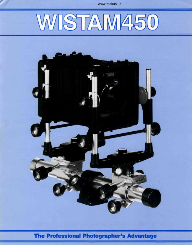
WistaPDF
WISTA M450 Flier
User manual
13 pages · EnglishRead →
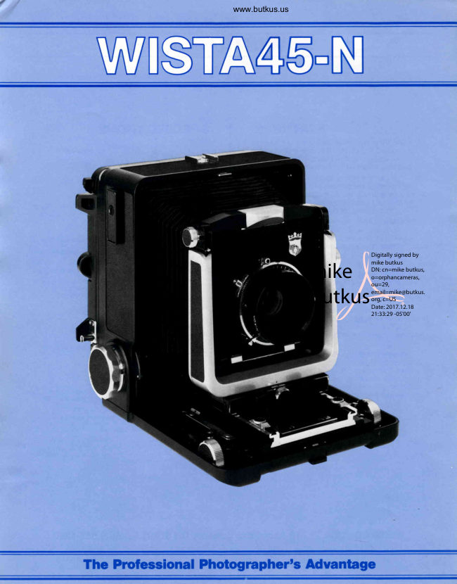
WistaPDF
WISTA 45-N
User manual
3 pages · Not specifiedRead →

WistaPDF
WISTA 45SP
User manual
4 pages · Not specifiedRead →
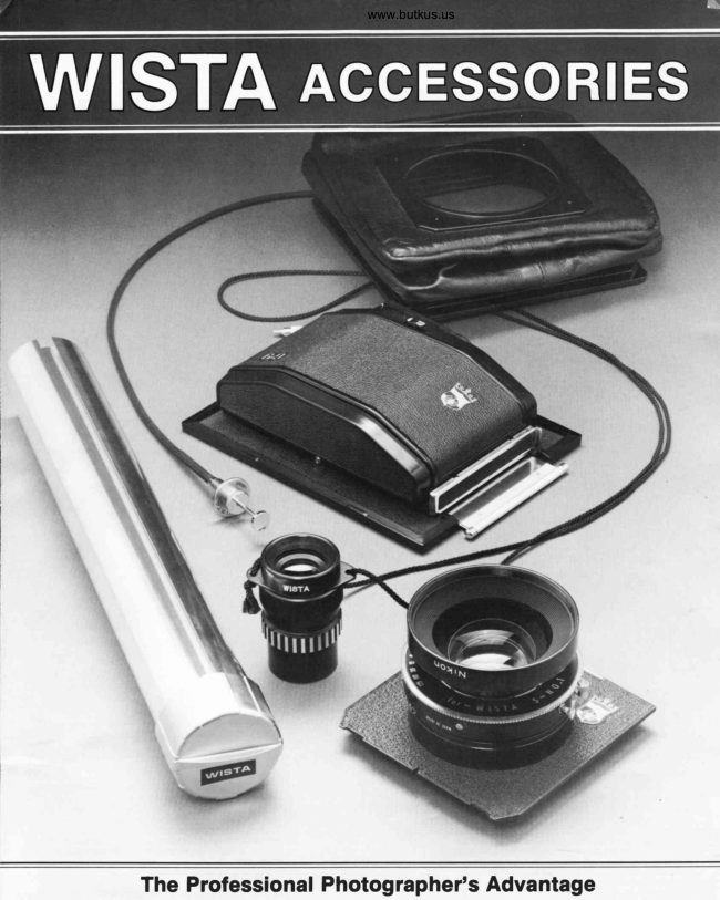
WistaPDF
WISTA Accessories
User manual
5 pages · Not specifiedRead →

WistaPDF
WISTA FIELD-45DX
User manual
3 pages · Not specifiedRead →
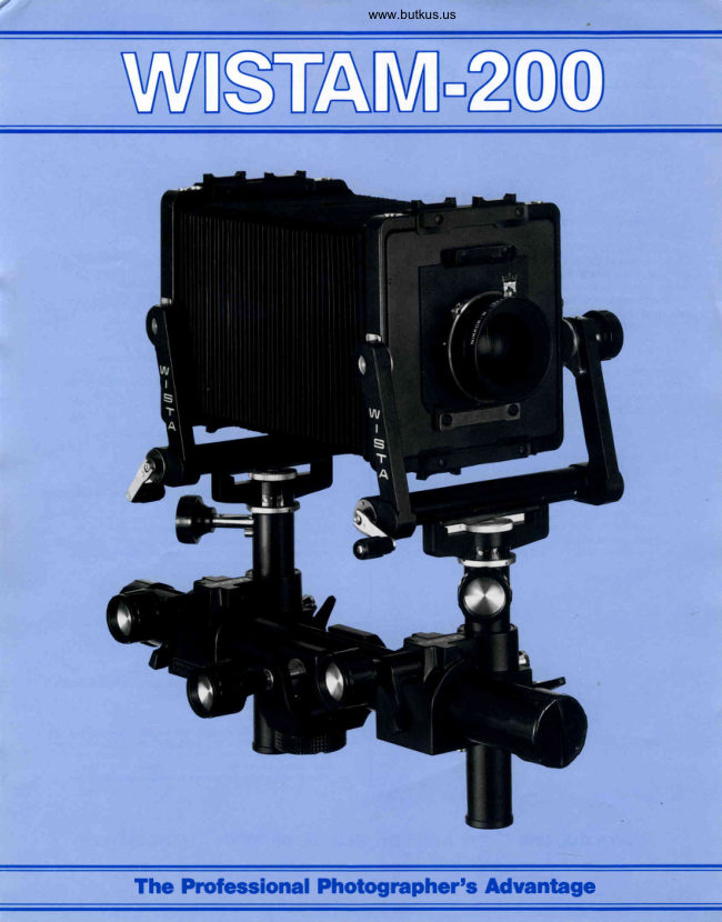
WistaPDF
WISTA M-200
User manual
3 pages · Not specifiedRead →
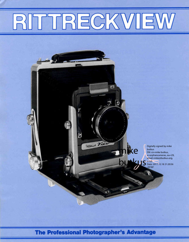
WistaPDF
WISTA RITTERCK VIEW
User manual
3 pages · Not specifiedRead →
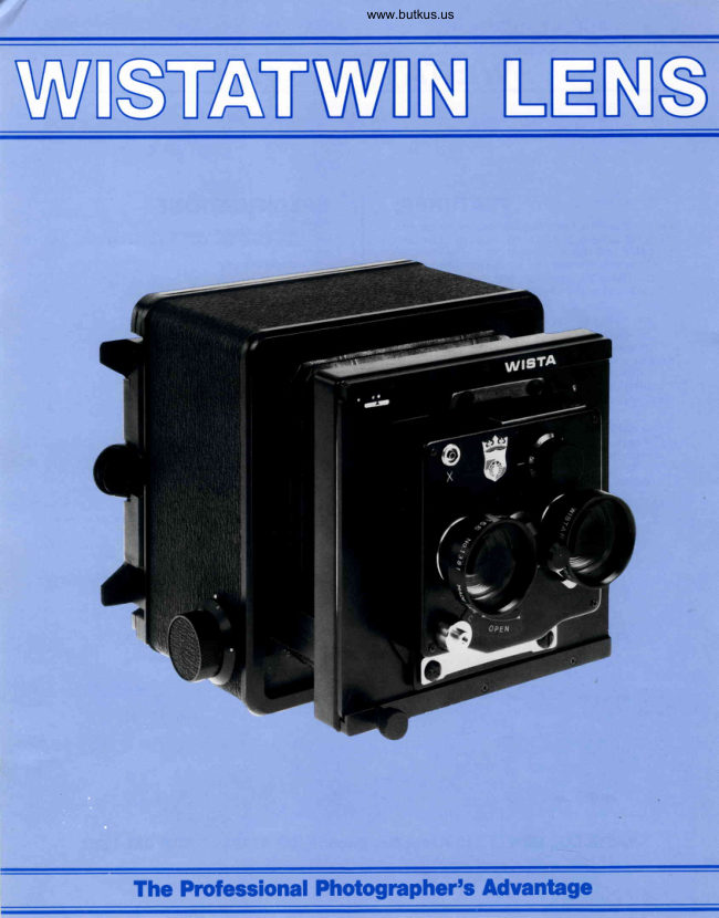
WistaPDF
WISTA TWIN LENS
User manual
3 pages · Not specifiedRead →
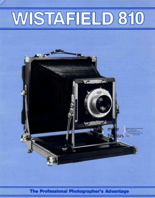
WistafieldPDF
WISTAFIELD 810
User manual
3 pages · Not specifiedRead →
From the M. Butkus archive. Original publisher and archive notices are retained.
Check the model and edition against your equipment.
PDF verified 2026-10-10.