Film cameras
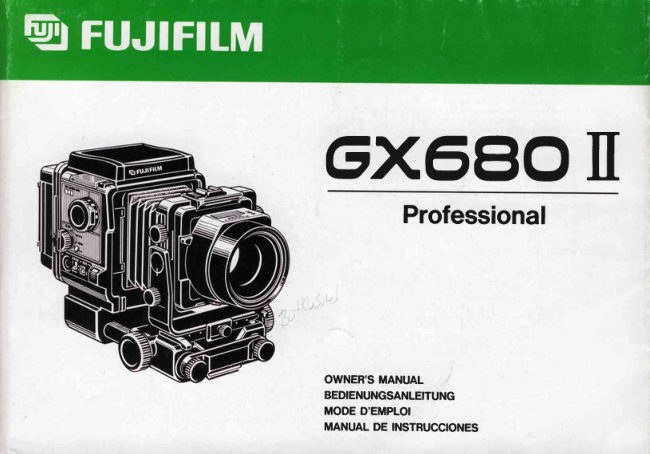
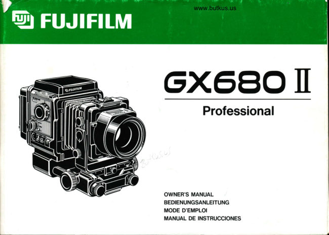
Fujifilm GX680 II User manual
User manual for Fujifilm GX680 II. 24 pages in German, French, Spanish. Read the original PDF, download or print a copy without registration.
24 pagesGerman, French, Spanish3.0 MB PDF
Loading your manual…Open PDF directly
Document details
- Brand
- Fujifilm
- Model / document
- Fujifilm GX680 II
- Document type
- User manual
- Language
- German, French, Spanish
- Pages
- 24
- File size
- 3.0 MB
- Category
- Film cameras
- Document date
- Not specified in catalog
Search available document text
Find a term, then jump to its page in the original PDF. Image-only pages may not be searchable; check the PDF for exact wording and diagrams.
Page 1 · Read text
G)(6,E|0I[
      Professional


OWNER'SMANUAL
BEDIENUNGSANLEITUNG
MODE D'EMPLOI
MANUAL DE INSTRUCCIONES
View original page 1Page 7 · Read text
OWNER'SMANUAL                                                                          Engllsh (Pages 10 - 23)
This manualwill show you how to use and care for your FUJI GX680II Professional         See illustrations while you read this
correctly.Pleasefollow the instructionscarefully.                                         manual.


Bedlenungsanleltung                                                                     Deutsch (Selte 24.- 38)
Diese Anleitung enthilt  alles, was Sie Uber die Bedienung und Pflege lhrer FUJI            Orientieren Sie sich beim Durchlesen
GX680 II  Professional wissen mussen. Lesen Sie die Anleitung bitte aufmerksam             dieser Anleitung bitte an den Abbil-
durch.                                                                             dungen.


MODED'EMPLOI                                                                           Frangals (Pages 39 - 3l)
Cette brochureest destin6ei vous documentersur I'utilisation et I'entretien de votre          Se reporter aux illustrations en lisant
FUJIGX680lIProfessional.Veuillezlire attentivementces explications.                                 le mode d'emploi.


MANUALDE INSTRUCCIONES                                                           Espafiol(P6glna55 - 70)
Este manual le explica c6mo utilizar y  cuidar correctamente su FUJI GX680 II           Consulte las ilustracionesmientras
Professional.Sirvaseseguir atentamentelas instrucciones.                                    lee este manual.
View original page 7
Page 13 · Read text
@ Shutter Release                                                            get which film you are using.
                      It is operatedby pressing it down with the right thumb so that the cam-    @ Revolving Lock
                                                                                                                                 pushingit in. mzor           era can be kept still even when taking hand-heldshots.                     To dismountor revolvethe film holder,releasethis lock by
                                                              Memo                                                                                Space                                           @                       Lever@-    @ Stop-down                                                                                                                           jot down exposurenotes in this space with a pencil and erase                                                                       You                                                                                 can                               the depth of field of your picture through the view-                     It lets you preview
              finder quicklyand easily.                                            them with a rubber eraser.
             Aperture Selector                            @ Dark Slide Pocket     o                      It is located on the lens underside to prevent moving it inadvertently       When taking pictures,pull out and insert the slidingcover in this pock-
           and is providedwith click stops at each step.                                       et so that you won't misplaceor lose it.
    @ Focus Lock Lever                            @ Aperture Indicator Window
                      It keeps the lens fixed in precisefocus.                                 The apertureyou have selectedwill appearin this acrylic-resinwindow.
     @ Focusing Knobs                             @ Lens Lock
          Two large knobs, one on each side of the camera, let you focus the                   It locks the mounted lens securelyin place.
             lens easily.                               @ Spirit Level
     @ CollapsibleFinder Hood                                                                                       It lets you keep the camera levelon a tripod or camerastand.
                      It springs up and folds down with a finger'stouch.              @ Film Speed Selector
     @ Bellows                                                                                                               It lets you set the camerafor the speed of the film loaded in it from ISO
           You can change the bellows to suit the situation-  to wide-anglebel-          25 to 1600 in 1/3-step increments.(lt links the film speed to the
            lows if you are using camera-frontmovements,and to long bellows if           incorrect-exposurewarningmonitor and AE finder).
            you are taking close-ups.                         @ LCD Exposure Counter
     @ Rise/Fall Knobs                                               A large-sizeLCD shows whether the film is advancingor not. lt also
           To use the rise or fall movementto change the position of the objects         shows the total number of shots taken.
                in your picture,loosen these knobs.                  @ Hotshoe
     @ Tilt Knobs                                                            Located in the center of the lens mountings,it moves in unison with
           To tilt the camera front upward or downward to adjust top-to-bgttom            the lens' opticalaxis during camera-frontmovements.
            sharpness,loosenthese knobs.                   @ Lens Lock Release
    @ Shift Knob                                                       To activatethe lens lock, the lens lock releasemust first be pushed in.
           To shift the camerafront laterallyto the left or right to changethe posi-           This two-step action is used to prevent disengagingthe lens inadvert-
               tion of the objects in your picture,loosen this knob.                                ently.
    @ Swing Lever                               @ Finder Lock
           To swing the camera front to the right or left to adjust right-to-left         To dismountthe finder,just push in the finderlock.
            sharpness,push the swing leverdown.                   @ Stand-by Monitor
     @ Battery Lock Button                                                                         Its LED indicatorsshow the conditionof the battery pack, the camera's
             For releasingthe battery lock to disengage the battery pack or DC           readinessto take pictures,as well as any abnormalcamerabehavior.
           power supply connectorfrom the camera.                 @ Shutter Speed Selector
     @ Battery Pack                                                                                                        It can be set to B, 8 to 1/400-second,and AE (Auto).The AE mode is
             Quick-chargingthis special7.2-voltNi-Cd battery pack for an hour will           operativeonly when the AE finderis mounted.
                 let you take about 1,000shots.                       @ Incorrect-exposureWarning Monitor
     @ Camera Back Lock                                                                                               It detects the amount of light reflectedby the film by means of an inter-
           To open the camera back, erect the lock and push it down. This two-            nal light sensor. lf the exposure setting is within two stops over or
             step action is designed to prevent accidentalopening of the camera          under,it will spell out "EXP" in green letters,and if the exposureset-
              back.                                                                            ting is more than two stops over or under,it will show a plus (+) or
     @ Film ReminderSlot                                                  minus (-) sign with its LEDs. lt shows apertureand shutter-speedmis-
            Tear off the film-box top and insert it in this slot so that you won't for-1 2                             www.butkus.us
View original page 13Page 14 · Read text
(Flg.s-A)    settings           immediately                           after                             the shot                                                 is taken.                                  When                                                   shooting                                                                with                                                                   the          Mountlng                                                                                               (Flg.3-81                                                               Ia   remole-control                   shulter                          release,                            and the                                     exposure                                                      setting                                                                     i3 more                                                              than                                                                                 Battery Pack
   lwo stops over or under, it emits an audible electronic warning. (lts          Dismounting(Fl!.3-C)                                                                                                J(,                                                                                                                                         z
                                                                                                                                                                                                                                                                                                                           t.rJ   coupling range is from EV 4 - 18. ISO 100).                                     Battery Lock Button (Ftg. 3-D)
@ Fllm Tr.Nport  Indicrtor                                                           (2) U.lng an A.C. pow.r source (Flg.4)
       ll can tsll you accurat€ly wh€th€r th€ film is advancing or not b€caus€          Fit the DC Power Supply's conneclor onto tho left sid6 of lh6 camela body
      it  is connected directly to the exposure counter's roller shaft and          in lhe same way as the Battery Pack, plug the A.C. cord into a wall outlet,
   makes approximat€lyone full turn as sach frams is advancsd,              and turn on lhe OC Power Supply's main switch.
@ Total Shob Indlclto. Button                                  DC Pow€r Supply Connector (Flg. il-A)
   By counting th6 numb€r of frames advanc€d by €ach film hold€r. it          Connector Cord (Fig.4-B)
   shows on an LCD th€ aggregat€ number of frames advanced in units of          lollce;
   100 so that you'll know whether the camera needs overhaulingor peri-       You cannot mount the Bettery Pack or fii on tho OC Pow€r Supply's con-
    odicel mainlenance,                                                       nector with the bellows compressed. You'll have to fkst draw oul the lens
@ CrluLlght Button                                                     assembly.
   Pressing in this bulton will light up pan of th€ LCD so lhat you can
   ch6ck lh6 exposuro counler ev6n in the dark. lf ih6 film holder is de-          3. MOUl{fll{O Al{D DBllOUim  G THE LEI{S
   tached from lhe carhera,it will show the number in lhe counter with its          (1) Mountng Glg.5)
    built-in back-up battery (lh€ lamp will not turn on in this case).                 Lens Lock Release(Flg. 5-A)
                                                                     L€ns Lock (Flg. 5-B)
l.  GETTING READY TO TAKE PICTURES                                 Whil€ pushing the Lens Lock R€leas€ toward th6 cam€ra back, lift up th€
                                                                   Lens Lock. The Lens Lock will now remain in litled position. Nsxt, hold the
l.  MOUNTINGTHE CAITERA ON A TFIPOD OR CA ERA STAND (Fig. 1)         lens with lh€ apenur€ scal€ up, hook the lensboard boltom on lhe lens
Th6 cemera is provid€d in th€ boltom with a 1/4-inch and a s/8jnch t.ipod        mounling then press the lens against the lens mounting. The Lens Lock
socket,                                                                                            will automaticellyrsturn to locking position to lock the lens in place,
a 96 sur€ to us6 a hoavily-builttripod or cam€ra sland that is equipped        Notlce:
   with a sturdy mounling head.                                                                                        lf the lsns is not corr€ctly mounled, faully connection will cause the Stand-
   3/8-inch Tripod Sock€l (Flg. l-A)                                         by Monitor to blink, so you'll have to remount ths lens corecily.
   1/+inch Tripod socket (Fig. 1-B)                                                   (2) Dl.mountlng (Flg,6)
                                                                Whib supporting the lens with one hand, push back th€ Lens Lock Re-
2. POWER SOURCE                                                      teas6 and tift lh6 Lens Lock with the other. That's all.
The GX680 Il can be ussd wlth a spoclal Balt€ry Pack or an A.C. pow€r        Notlce:
Sourc€ lo suit your convenience,                                      To prsveni dropping th€ l6ns, be Sul€ to support  it with One hand while
a To use an A.C- power source, you'll have to use the camera's special        dismounting il,
  DC Power Supply unit.
o The Batlery Pack can be charged with the camera's special Battery         4,  OUim  c AXD DTSMOUNTTOTHE F|LM HOLDER AirO
   Charg€r.                                                           REVOLVtt{c tT
(1) Ullng the battery peck (Flg!.2 & 3)                                              (1) lilountlng (Fig.7)
First, charge the Battery Pack lhen mount ll on the cemeraes follows:             Lins up th€ uppsr edg6 of the Film Holder with the hyphenated reference
Align the back end of the Battery Pack with the reference line on the left          line on the Camera Back and, while pressing the Fllm Holder against ths
side of ths cams6 body lhen slid€ it back toward the Filrn Hold€r.              Cahera Back, turn it toward the right (Sse arrow) so that it tocks into hori-
  Reference Line (Fig.2-Al                                                     zontat position with a ctick. (you'll have to press in the RevotvingLock to
fo  dismount the Battery Pack, sllde  it loMard  toward lhe lens whll6         turn the Holdsr).
pressing in the Battery Lock Button.                                       Hyphenatedreference line (Flg. t.A)
                                                                                                                           1 3
View original page 14Page 15 · Read text
m         Dismounting(Fig. 7-B)                                                        (Fig. 12).
 z
 or          MountingRevolving(Fig.Lock7-C)(Fig. 7-D)                                                                                         lfa theBatterybatterypowerpacklow:is insufficientlycharged,an orange LED will light up or v)   I           (2) Dismounting (Fig. 8)                                                        blink (Fig. 12).
             First, make sure the Dark Slide is insertedin the Film Holder.Next, release
           the RevolvingLock by pressing it in, then turn the Film Holder 45o to the           Battery power                        Readinessto take pictures
              left and dismountit.                                                                   Sufficient--+ Green LED ----r---Lights up -+ Yes
           The Film Holder is set horizontally(Fig. 8-A)                                                                                                               I   Blinks   -+ No
            (3) Revolving(Figs. I & 10)
         To change the positionof the Film Holderfrom horizontalto vertical,turn it            Low----------+Orange LEDTLights    up -+ Yes
                                                                                                                                                                                                                 I   Blinks   -+ No         90o to the right, and from verticalto horizontalturn it 90o to the left. (You'll
         have to press in the RevolvingLock to do it.) lt will fall into the correct ver-
             tical or horizontalpositionwith a loud click.                                    Notice:
          o Revolvingcan be done with the SlidingCover removed.                     o  lf the LED lights up, the camera is ready to take pictures; if it blinks,the
          o You'll have to press in the RevolvingLock to mount, dismount,and re-        camera is not ready.
             volve the Film Holder, but once you press it in and move the Holder       o  lf you are using the DC Power Supply, it is the green LED that will al-
           even slightly,you can take yOurfinger off it. There is no need to hold it        ways light up or blink to tell you that sufficientvoltageis available.
           down.                                                              o  lf the Battery Pack is charged for an hour in normal temperature,it will
              Verticalto horizontal(Fig. 9-A)                                                             let you take about 1,000shots (providedthe batteriesare new). lf the                                                                         .. . .6rUJ
             Horizontalto vertical(Fig. 9-B)     )i-V                                   orange LED has just started to light up or blink, it means the Battery                                                                                     t                                   Pack is insufficientlycharged but there is still enough power left in it to            RevolvingLock (Fig. 9-C)    W
           The Film Holder is set vertically(Flg. 10-A)                                    take about 50 shots. lf the battery voltagefalls below the requiredlevel,
                                                                                        the camerawon't operateand neitherthe green nor the orange LED will
            5. ATTACHINGAND DETACHINGTHE REMOTE-CONTROLSHUTTER             turn on any more.
         RELEASE(Fig.11)                                                                (2) Readiness to take pictures
         To attach, plug it into the socket marked RC in the lower right hand side of      The green or orange LED will tell you whether you can just press down the
           the camera.To detach,just pull it out.                                        Shutter Releaseto take your picture or not. This signal is based on wheth-
            Remote-controlShutter Release(Fig. 11-A)                                    er the Lens and Film Holderare properlymounted or not, whether the Slid-
                                                                                         ing Cover is in or out, and whether the Shutter Speed Selector is set to
                 II. LED INFORMATION PANEL                                             the selectiveor AE mode.
                                                                                o Camera ready
            1. STAND.BYMONITOR                                                                                            lf the camera is ready to take pictures,either the green or orange LED will
         The Stand-by Monitor's LED indicatorswill show you the condition of the          light up. The color of the LED depends on the condition of the Battery
          Battery Pack, whether the camera is ready to take pictures or not       Pack (whetherthe power is sufficientor low). (Fig. 12).
          (whether the lens and Film Holder are properly mounted or not, whether       o Camera unready
          the Sliding Cover is in or not, and whether the Shutter Speed Selector is              lf any one of the conditionsjust mentioned is not in proper order, either
           set to the selective or AE mode), and whether the camera is behaving       the green or orange LED will blink and the camera won't operate. This
          normallyor not (action of the shutter blades,movementsof the mirror and      means you'll have to check whether the SlidingCover is in or out and
            light shield and behaviorof the film transport unit).                         whetherthe Film Holderand Lens are properlymountedor not. Again the
            (1) Battery condition (Fig. 12)                                                  color of the LED dependson the power levelof the BatteryPack (Fig. 12).
           Green LED (Batterypower sufficient)(Fig. 12-A)                             Notice:
           Orange LED (Batterypower low. Batteryneeds charging)(Fig. 12-B)           o  lf the camera is mounted with Instant Film Holder1r rememberthe LED
          a  Battery power sutlicient:                                                               will turn on and blink continuouslybut you can operate the Shutter
                   lf the battery pack is sufficientlycharged,a green LED will light up or blink         Releaseby switchingthe camerato the Multi Mode, and if it is mounted1 4                             www.butkus.us
View original page 15Page 16 · Read text
with Instant Film HolderII, the LED will turn on and just glow.                             lf the apertureand shutter speed are set so that exposurewill come within                                                                                                                                                                                                    -ao  lf you are using the CollapsibleFinder Hood and the Shutter Speed Se-       2 stops over or under,green LEDs will spell out the letters "EXP"                                                                                                                                                                                                                                      J(5   lector is set to the AE mode, the LED (greenor orange)will alwaysblink.         (2) lf the red LEDs show the plus (*)  or minus (-) sign                                                                                                                                        z  Be sure to set the Shutter Speed Selector to the AE mode only when              lf the aperture and shutter speed are set so that exposure will be more                 IJJ
  you are using the AE Finder.                                           than 2 stops over or under,red LEDswill show eithera plus (*)  or minus
(3) Abnormalcamera behavior (Ftg. 13)                                                     (-) sign (Fig. 14). This will give you a rough idea (right after you finish tak-
  Green LED (Fig. 13-A)                                                       ing a shot) of the kind of exposureyou will get, and also point out the ap-
  Orange LED (Fig. 13-B).....Blinkalternately                                   erture and shutter-speedsetting mistake you made, However,if you are
lf the Shutter,Mirror, or Light Shield behavesabnormallyduring exposure,       using the Remote-controlShutter Releaseand the exposureyou have set
the green and orange LEDs will blink alternately,the ElectronicWarning         is more than 2 stops over or under, an electronicwarning buzzer (700 Hz)
Buzzer (3.5 kHz) will buzz for three seconds, and all camera movements         will buzz intermittentlyfor five seconds.
will come to a halt. And if there is anythingwrong with the Film Holder,the        Notice:
Holder's LCD indicatorswill blink, the buzzer will sound, and all camera             lf the camera is not loaded with film, the internalsensor will measurethe
movementswill stop.                                                                   light reflectedby the film pressureplate,which means the LEDs will invari-
Notice:                                                                    ably show the minus (-) sign.
In practicallyall cases the cause of the trouble signals is faulty Lens or          Film Speed Selector (Fig. 15-A)
Film Holder contact. lf you think that is the trouble spot, dismount the          Film Speed Scale (Fig. 15-B)
Lens and/or Holder, clean the contact areas with an air blower, and        Notlce:
remountthem.                                                         o Be sure to set the carnerafor the speed of the film you are using by
 o The GX680II monitorsthe conditionof the Mirror, Light Shield,and Film          turning the Film Speed Selectorprovidedon the Film Holder.
  TransportUnit with a photo-couplerand stops all camera movementsin       o  lf you are shooting with instant film, the Incorrect-exposureWarnilg
  case of trouble. This safety measure has been adopted to avoid the          Monitor will not operate.
   worst possible situationthat can be encounteredin picture taking, that       o Since the reflectionindex of roll film may differ by about 1 f-stop be-
    is, making the serious mistake of shooting with a damagedcamera and         tween brands,the LED indicationsshould be used only as a criterion.
   getting unexposedframes.                                             o The LED indicationswill also vary depending on the reflectivityof the
Notice:                                                                         subject,which could be high key, low key, white, or black.
lf the Film Holder is mounted without its inner frame, the ElectronicWarn-       o The GX680 II  is factory-adjustedto the film reflectance of Fujicolor
ing Buzzerwill also buzz just as though the camera were behavingabnor-          negativefilm and Fujichromereversalfilm and to the subject reflectance
mally.In this case, however,either the green or the orange LED will blink           of a standard 18% gray card.
(dependingon the condition of the Battery Pack) to warn you that the        o For the reasons just mentioned,dependingon the picture subject and
camerais not readyto take pictures,but the LEDs will not blink alternately.         the film that is used, even if the red LEDs show the plus (+)  or minus
                                                                                                         (-) sign, it doesn't pecessarilymean that the exposure is always more
2. INCORRECT-EXPOSUREWARNINGMONITOR                             than 2 stops over or under.
When a subject is photographed,light passes through the lens and ex-
poses the film, but it is reflectedback at the same time. The light sensor in            III. BASIC PROCEDURES
the camera body detects the quantityof light that is reflectedback and in-
dicatesthe amount of exposurethat has been furnishedby means of LEDs.         1. SETTINGTHE MODE SWITCH
 o The exposure amount furnished is indicatedby means of LEDs regard-         (1) Otf mode (Fig. 16)
   less of the nature of the exposing light, be it daylight,tungsten light, or           Film Wind Button (Fig. 16-A)
   flashlight.                                                  Mode Switch (Fig. 16-8)
(1) lf the green LEDs spell out the letters "EXP" (Fig. 14)                   Mode Switch Lock (Fig. 16-C)
 .. More than 2 stops over (Fig. 1a-A)                                  To turn off the power source, the LED displays,the Film Holder's LCD
  Within2 stops over or under (Fig. 14-B)                                         (liquid-crystaldisplay),and the camera itself,just turn the Mode Switch to
  More than 2 stops under (Fig. 14-C)                               OFF.                                                                                                                           1 5
View original page 16Page 17 · Read text
m         (2) Single mode                                                 The settingspossibleare B,8  - 1/4O0-second,and AE (Auto).Since the  zo           Settingthe Mode Switch to the SingleMode will turn on the power and ad-        shutter is the interlenstype, electronicflash will synchronizewith all shut-  t-         vance 1 frame in about a second each time the Shutter Release is de-         ter speeds.
 U)-       pressed.                                                                                                                       lf you are using the AE Finder,press in and hold down the AE Mode Lock
            (3) Continuousmode                                                     then turn and set the ShutterSpeed Selectorto AE (Auto).
          With the Mode Switch set to the ContinuousMode, the film will keep ad-       To switch the Shutter Speed Selectoroff the AE Mode, you'll also have to
          vancingat the rate of 1 frame in about a second as long as the shutter       do it whilepressingdown the AE Mode Lock.
         Releaseis depressedto let you take rapid-sequenceshots.                    o The Shutter Speed Selector cannot be set to intermediatespeeds
            (4) Multi mode                                                       (speedsnot shown on the scale).
         To set the Mode switch to the Multi Mode or release it from this mode.
           slide the Mode switch Lock toward you and rotate the switch (Fig. 16). lf         5. SETTINGTHE APERTURESELECTOR(Figs. 20 A 211
          the camera is set to the Multi Mode, the film will not advancewhen the          ApertureScale (Fig. 20-A)
           shutter is released.                                               The aperture is set by using the Aperture Selector located on the side of
            (5) Using the tilm wind button                                                the lens barrel.Each step is providedwith a click stop.
        To advance the film a frame after taking a multiple-exposureshot, just        o The aperture can be set to intermediatevalues (valuesnot shown on
          press in the Film Wind Button.                                                 the scale).
          o To wind the film in mid-roll,use this button.                                o since the GX680II is an interlens-shuttertype single-lensreflex camera,
          o  lf the Mode switch is set to the single or continuous mode, the film will          focusing is normallydone with the aperture wide open. To previewthe
             not advanceeven if the Film Wind Button is depressed.                       depth of field of your picture, just push down the Stop-down Lever
          o  lf the Mode switch is switched on. and left as it is, it will automatically         located on the right hand side of the lens barrel.
            switch off in 15 minutes.                                             Stop-downLever (Fig. 21-A)
          To switch it on again, first switch it to OFF and then to the mode you          ApertureSelector(Fig. 21-B)
           want (but this appliesonly when the camera is being poweredby the
            BatteryPack).                                                                    6. TAKTNGFLASH PICTURES(Figs.22 & 23)
                                                                            Hotshoe (Fig.22-A)
           2. USINGTHE SHUTTERRELEASE(Fig. 17)                               Sync Socket (Fig. 23-A)
                  lf the camerais readyfor shooting,just press down the shutter Releaseto           Shutter Release(Fig. 23-B)
          take your picture.                                                 The GX680II has a Hotshoe on the lens mounting and a sync socket on
            Shutter Release(Fig. 17-A)                                                the body. Both are X-contacts.And since the shutter is the interlensrype,
                                                                                           flash will synchronizewith all shutter speeds.
           3. USINGTHE REMOTE-CONTROLSHUTTERRELEASE(Fig. 18)                            lf you are using M-class bulbs, the shutter must be set to 1/3O-seconoor
         Plug the Remote-control Shutter Release into the camera's Remote-       stower.
          control Socket (marked RC) and, if the camera is ready for shooting,take        Caution:
         your picture by pressingdown its ReleaseButton.                        You can use infraredsynchronizersthat are designedto synchronizecord-
        The hook on the grip is used for hangingthe grip on the tripod's panning        less flash and camera, but practicallyall of these devices are equipped
          rod or some other convenientplace when not in use.                            with built-in flash. A few of them, however,operate on built-in LEDs and
                  lf you are using the Remote-controlShutter Release and have set the       slow-responsereceivers.Be carefulwhen you use these time-lagunits be-
        cameraso that exposurewill be more than 2 stops over or under, an elec-       cause they can sometimesfail to fire the flash.
           tronic warning buzzer will turn on to warn you. (To adjust the sound level
           of the buzzer,see the instructionson page 20).                                     7. USINGTHE FINDERHOOD
                                                                                                (1) Expandingthe hood (Fig. 2a)
           4. SETTINGTHE SHUTTERSPEEDSELECTOR(Fig. 19)                        Just lift the hood cover up and it will spring into positionby itself.
         AE Mode Lock (Fig. 19-A)                                            OpeningNotch (Fig. 24-A)
16          ShutterSpeed Selector(Fig. 19-B)          www.butkus.us
View original page 17Page 18 · Read text
(2) Using the magnlfler (Fig. 25)                                     may be rejected when camera-frontmovementsare employed(particu-                    I
  Puttingaway the Magnifier(Fig. 25-A)                                               larlytilt ups and falls).                                                                                      I                                                                                                                                                                                                                                                                                                                   J(9  Magnifier(Fig. 25-B)                                                   o However, since the image circle of the GX680II's interchangeable
  MagnifierLever (Fig. 25-C)                                                lenses have room to spare even when maximum camera-frontmove-           zLU
  Flippingup the Magnifier(Flg.25-D)                                    ments are employed,the upper edge of the Finder image will register
  Collapsingthe FinderHood (Fig. 25-E)                                   on the film even if it is rejected by the mirror.
When you look at the camerafrom the back, you will see a small lever near        o To eliminatefinder-imageedge blur resulting from mirror rejection of
the Opening Notch in the right hand side of the Finder Cover. To flip up          the image when a long focal length lens is used, just set the camera
the Magnifier,just slide this lever to the right. To put it away, push down           front to the "rise" position (see camera-frontmovement:rise and fall).
the MagnifierBoard.
(3) Folding down the hood                                                          9. FOCUSINGTHE LENS (Fig. 28)
After putting the Magnifieraway, place your thumbs against both sides of          Focusing Knob (Fig. 28-A)
the Hood along the hinges and push them inward.That's all. The Hood will         Focus Lock Lever (Fig.28-B)
collapseand fold down by itself.                                             Braking Direction(Fig. 28-C)
(4) Mounting and dismountingthe finder hood (Fig. 26)                        Focusing Knob (Fig. 28-D)
  Dismounting(Fig. 26-A)        v, ,tg ru )                                 While looking at the image in the vieMinder, bring it into focus by turning
  Mounting(Fig.26-8)      (A,r1["                                          the Focusing Knobs (one on each side of the camera).
  FinderLock (Fig. 26-C)                                                o After focusing, use the Focus Lock Lever to lock the focus in place.
To dismountthe Finder Hood, slide it toward the lens while pressingin the        Notice:
FinderLock (locatedin front of the LED displaysector of the camerabody).      To permit camera-front movements with the lens set to  infinity, the
To mount, insert the hooks in the bottom of the Finder into the holes in        interchangeablelenses of the GX680II are not provided with an infinity
the camerabody and slide the Findertoward the cameraback.                    stop.
8. FRAMINGYOUR PICTUREGi'g-271                                            IV. USING THE FILM HOLDER
  FramingIndicator(Fig. 27-A)                                                 (separate film holders lor 120 and 22Ol
The frames for horizontaland vertical composition are marked out with
black lines in the viewfinder.These are used by revolvingthe Film Holder        1. OPENINGAND CLOSINGTHE CAMERABACK (Fig.29)
to the desired position.                                                      Erect and push down (Fig. 29-A)
When the Film Holder is revolved into horizontal position, the Framing      To open the CameraBack, erect the CameraBack Lock ahd push it down.
Indicatorwill appear in the top and bottom of the Finder and when it is      To close it, replacethe CameraBack with the Lock erect then snap down
revolvedinto vertical position,the Framing Indicatorwill appear in the left       the Lock.
and right sides of the Finder.
 o  lf you are using InstantFilm HolderlI, you can attach a framing mask to         2. INSERTINGAND EXTRACTINGTHE FILM HOLDER'SINNER FRAME
     it that interlockswith the Finder's FramingIndicator.                          (Fis.30)
 o  lf you are using InstantFilm HolderI, rememberthe FramingIndicator        Upper surfaceof the inner frame (Fig. 30-A)
    will remainfixed in verticalframing position only.                       To extract the Inner Frame,squeezethe two center projections(as shown)
Notice:                                                                             to releaseit from the outer frame and pull it out.
 o Since the mirror length is restricted by the body construction,depend-      To insert, squeeze the center projections inward and push it in. Next,
   ing on how far the bellowsis drawn out, you may not be able to see the       check to make sure it is locked to the outer frame by gripping its center
  upper edge of the Finder image. With a 250-mm focal-lengthlens or       and pullingit.
   longer, the upper edge of the Finder image will be rejected even if the        Notice:
   lens is set to infinity.                                            To prevent damage to the rails, the inner frame is factory-packedwith ", o On account of the restrictedmirror, the upper edge of the Finderimage        milky-whiteprotectivefilm. Be sure to remove it.
                                                                                                                           1 7
View original page 18Page 19 · Read text
m         3. LOADING THE TAKE-UP SPOOL AND FILM (Figs. 31 & 32)                     the "1 EXP" sign will appear in the Counter (Fig. 06).  zo             Film Take-upGear (Fig. 31-A)                                        The same goes for the other frames. For instance,after frame No. 4 is   t-
           Upper surfaceof the inner frame (Fig. 31-B)                              exposedand frame No. 5 moves into positionfor exposure,the Counter a
            Spool Holders(Fig. 32-A)                                                                  will show the "5 EXP" sign (Fig. 37).
           Bottom surfaceof the inner frame (Fig. 32-B)                              o The Exposurecounter will count up to "9 EXp" in the case of 120 roll
            Insert the spool in the Take-up-Gearside and insert the film in the oppo-            film,and up to "18 EXP" if you are using220 rollfilm.
            site side. Both spool and film are loaded by pulling up the spool Holders      oAs soon as the "9 EXP" (120 roil fitm) or "18 EXp" (220 rol fitm) sign
          providedon the bottom side of the Inner Frame.                              appears in the Counter, the Last Frame Warning Buzzer (1 kHz) will
           Notice:                                                               buzz intermittentlyfor 2 seconds to tell you there is only one frame left
         The innerframe can be used in both the 120 and22OFilm Holders.                    (Fis. 38).
                                                                                o After the last frame is exposed, the Counter will show the ,,End" sign,
            4. POSITIONINGTHE FILM STARTMARK (Fig. 33)                               the film will wind itself up to its very end, and the camera mechanisms
          Since a photo-coupler in the Film Holder keeps constant check on the             will come to a halt (Fig.39).
          paper leader and trailer and senses whether there is film in the camera or         (2) Total shots indicator (Figs.40 & 41)
           not, the start mark in the Inner Frame and the film start mark do not have          Total Shots IndicatorButton (Fig. a0-A)
            to be lined up precisely in order that the camera can position the first           Call/LightButton (Fig. a0-B)
         frame correctly.You can just wind the paper leader on the take-up spool          Total Shots IndicatorWindow (Fig. aO-C)
         and line up the film start mark with the Inner Frame'sstart mark in an ap-       Pressing in the Total shots IndicatorButton will show you in units of 100
          proximatemanner. Be careful,however,because the first frame could be        the total number of frames that has been advanced(total number of shots
          spoiled by exposure to light if the film start mark is wound past the Inner        taken). This feature has been incorporatedto tell you when the camera
         Frame'sstart mark.                                                 needs overhaulingor periodicalmaintenance.(Fig. 41)
          o  fn the case of 220 roll film, there is quite a bit of space between the tip        Notice:
               of the paper leaderand the start mark. You can thereforewind the front       Though new, some units will show that they have been factory-testedup to
           end of the paper leaderon the take-up spool and insert the Inner Frame       about 200 shots.
              into the outer frame (Film Holder) even if you cannot see the film start         (3) Call/Light Button (Fig. a2)
           mark at all.                                                           o Film holder mounted
             Film-loadingdiagram(Fig. 33)                                               with the Film Holder mounted on the camera,the LCD lamp will turn on to
             Inner Frame'sstart mark (Fig. 33-A)                                                    let you see the ExposureCountereven in the dark.
                                                                                o Film holder dismounted
            5. FILM HOLDER'SLIOUID.CRYSTALDISPLAY                                                       lf the Film Holder is dismountedfrom the camera,you'll have to press in
         To activatethe Film Holder's LCD, mount the Holder on the camera and        the call/Light Button to activatethe back-up lithiummemory battery that is
          switch the Mode Switch from OFF to the Singleor any other mode.                  built into the Holder in order to see the number of frames that has been
            (1) Readingthe exposure counter                                        exposed.
                   lf the Holder is not loaded with film, or if there is film in the Holder but it
         has not been advanced,you will see the "0 EXp" sign in the Exposure        6. AUTOMATICFIRST-FRAMEPOSITIONING
         Counter.                                                                       After loadingfilm in the Film Holder,turn on the Mode switch, pull out the
          o  lf the ExposureCounter is showing the "0 EXp" sign, you can open the         sliding cover, and close the camera Back. As soon as you completethese
          CameraBack without spoilingthe film (Fig. 3a).                              three steps, the film will automaticallyadvance into position for the first
          o As soon as the film starts winding, the "O---O" sign in the Exposure        shot.
            counter will blink to tell you the film is advancing.This sign will appear       a Example 1
           each time a frame is advanced(Fig. 35).                               Mode Switch on ------l
          Notice:                                                                                          FCtose   the Camera Back -+ Automatic film ad-
         Regardingthe start of film wind-up,see paragraph6.                                SlidingCover   -J                           vance
          o As the film advancesand the first frame is set into positionfor exposure,          pulledout
1 8                             www.butkus.us
View original page 19Page 20 · Read text
o Example2                                                              the Dark Slide,just press in the Lock Pin and pull it out.                           -                                                                                                                                                                                                                                                     I  Mode Switch on -l                                                    Lock Pin (Fig. a6-A)
                                                                                                                          (Fig. a7)                                                                                   Putting                                                                       away                                                                                              the Dark                                                                                                          Slide                                                                      film ad-        o                    FPull   out the Sliding Cover +  Automatic                                                                                                                                                                                                                                                                                                                                       Joz
                                                                                                                                                                                                                                                                                                                                                   l..rJ                                                                                                          (Fig.                                                                     Dark                                                                               Pocket                                                                                             a7-A)                                                                                    Slide  Camera Back     -l                                              vance
  closed                                                When taking pictures,pull the Dark Slide out and keep it in the Dark Slide
                                                                    Pocket so that you won't misplaceor lose it.                                                                    :o Example3
  Camera Back  ----l                                                      10.WINDINGAND UNLOADINGTHE FILM
  closed            l-Turn  on the Mode Switch -+ Automatic film ad-       Since the GX680II is a motor-drivencamera, the film will automatically
                                            vance                advanceto the next frame each time the Shutter Releaseis depressed.As                                     I
  SlidingCover                                                    soon as the Exposure Counter shows the "End" sign, open the Camera
  pulledout                                                           Back, take out the Film Holder's inner frame, and unload the film. Next, to
Notice:                                                                 prevent the film from loosening,seal it tightly with the End Seal.
The above examples apply to both the 120 and 220 roll film holders.
                                                                            11. A WORD ON THE BACK.UP LITHIUMBATTERY
7. SETTINGTHE FILM SPEEDSELECTOR(Fig. a3)                       The back-up lithium battery serves as the power source for the Film
  FilmSpeedScale(Fig.43-A)                                              Holder's"Exposure Memory" and "Exposure Counter" when the Holder is
  FilmSpeedSelector(Fig.43-B)                                       dismountedfrom the camera (it operates only as long as the Call/Light
The Film Speed Selector lets you set the camera for film speeds ranging       Button is depressed).
from ISO 25 to 1600in 1/3-step increments.                                                         It also serves as the power source for the "Exposure Memory" when the
o Since the Film Speed Selector is interlocked with the  Incorrect-       Holder is mounted on the camera but the power supply from the camera
  exposureWarningMonitor and AE Finder,be sure to set the camerafor       has been cut off, that is, the Mode Switch has been turned off. lf this bat-
  the speed of the film loaded in it.                                               tery is drained,the camera will therefore lose part of its faculties.lt has a
                                                                                                       life span of about five years.
8. USINGTHE MEMO SPACEAND FILM REMINDERSLOT (Flg. aa)                        lf the LCD indicatorsappear suddenly light and faded when the Holder is
  Film ReminderSlot (Fig. tl4-A)                                        dismountedfrom the camera compared to the way they appearedwhen
  Memo Space(Fig.44-B)                                                  the Holder was mounted, the back-up lithium battery is nearly spent and
The white Memo Space is used for jotting down exposure notes, etc. Pen-       needs changing. Your Fuji's distributors will replace it for you at a
cilled notes can be erasedwith a rubber eraser.                             reasonablecost.
The Film ReminderSlot is used for insertingthe top cover of the film box
so that you won't forget which film you are using.                               V. CAMERA MOVEMENTS

9. SLIDINGIN, SLIDINGOUT, AND PUTTINGAWAY THE DARK SLIDE            In normal photography,the lens optical axis passes through the center of
   (Figs.45& 46)                                                           the film at right angles. Camera movementsare used to take the optical
o Sliding in and sliding out                                                    axis away from film center, to cross the lens optical axis and film surface
Fit the leadingedge of the Dark Slide to the slot guide and push it all the        diagonally,etc. to control image perspectiveand sharpness.They let you
way in. The slot inlet is marked white so that you can see it even in dim       change the shape of objects in your picture, shoot subjects that have
light.                                                                 depth to them but which are sharplyfocused from one end to the other, as
To pull out the Dark Slide,hold its finger grip.                                    well as control the positionof objects in your picture without changingthe
o When the Film Holder is dismountedfrom the camera, a safety device      camera positionor angle.
  locks the Dark Slide so that it cannot be oulled out.                      The main camera movementsare the tilt and swing which involvean opti-
o The Dark Slide has no front or back side (both sides are the same).             cal twist and turn, and the rise, fall, and shift which involvea parallelmove-
Notlce:                                                          ment of lens and film, and the genericterm that encompassesall these de-
lf the Film Holder is dismountedfrom the camera but you want to pull out        viationsfrom normal is "camera movement."                                                                                                                           1 9
View original page 20Page 21 · Read text
m         1. RISE AND FALL (Fig. a8)                                              o With a standard bellows, you won't be able to use full camera move-
         These              movements                           are                        made by                                      loosening                                                  the                                                       Rise/Fall                                                   Knobs                                                                   located                                                                  on                                                                           ments if                                                                                                                                                                            it                                                                                                                              is                                                                                       compressed.                                                                                            The best thing you can do in such cases is to   zor          both sides                        of the lens                           mounting                                  and                                               raising                                                      or lowering                                                             the                                                                lens                                                                   face paral-                                                                           change                                                                                                            to                                                                                           a                                                                                          wideangle                                                                                                            bellows. U) -            lel with the line of the film plane. The rise is an upward, and the fall a
         downward movement.They are generallyused to make tall buildingsap-         VI. OTHER PROCEDURES
          pear verticalin your picture and to improvethe figure of portraitsubjects.
              Rise/FallKnob (Fig. 48-A)                                                        1. ADJUSTINGTHE SOUNDLEVELOF THE INCORRECT.EXPOSURE
                                                              WARNING BUzzER (Fig. 52)
            2. SHIFTS(Fig. a9)                                              Do not set the volume adjuster beyond the low and high points. (Fig.
         These movementsare made by looseningthe shift Knob and moving the           s2-A)
         camera front to the left or right parallelwith the line of the film plane by               lf the exposure you have set is more than two stops over or under, an
          pushing the shift Frame. lt is used to change the position of objects in        electronicwarning buzzer (700 Hz) in the grip of the Remote-controlshut-
          your picturewithout movingthe camera.                                             ter Releasewill turn on and buzz intermittentlyfor five seconds' and you
          o  lt can also be used to correct the position of the optical axis when       can adjust its sound level if you wish. To reduce the volume of the sound
            usingthe techniquecalled"swing"                                            or switch it off, turn the adjuster to the left, and to increasethe volume.
              Shift Frame (Fig. 49-A)                                                       turn it to the right.
              Shift Knob (Fig. a9-B)                                            To avoid damagingthe buzzer, however,do not set the adjuster beyond
                                                                                      the left and right stop points (markedwith dots).
            3. TILTS (Fis. 50)
         To tilt, loosen the two Tilt Knobs, one on each side of the camera,and turn         2. SHOOTINGwlTH THE MIRRORUP (Fig. 53)
           the camera front up or down. These movementsare used to control the           Mirror Up/Down Switch (Fig.53-A)
          top-to-bottomsharpnessof subjects having depth without stopping down           Mirror up (Fig. 53-B)
          the aperture.                                                                   Mirror down (Fig. 53-C)
                 Tilt Knobs (Fig. 50-A)                                                                                                lf you are taking long-exposureshots such as close-ups,or if you want to
                                                                                  avoid the time lag of the mirror movementto shoot a fast-movingsubject,
           4. SwlNGs (Fig.51)                                                                just shoot with the mirror up. This is the way to do it: After focusing the
         To swing, push the swing Lever (locatednext to the FocusingKnob on the        lens through the Finder,bring the mirror up by pushing up the Mirror
              left side of the camera body) and, at the same time, turn the camerafront      Up/Down switch then take your picture.After shooting with the mirror up,
            to the left or right. These movementsare generallyused to adjust right-to-        bring the mirror down again by pushing the switch down. Rememoeryou
              left sharpness,but they can also be used to control image perspective.         cannot take two picturesin successionwith the mirror up.
           Swing Lever (Fig. 51-A)                                                o  lf you are using on the GX6B0II a large size lens mounted on a Linhof
          o The camera movementsdescribed in the foregoing paragraphsare al-          board, you'll have to shoot with the mirror up, but you'll need an LF
           most always used in combination. Regarding details concerning the         LensboardAdapter (availableas an extra-costaccessory).
             principlesand techniques involved,please refer to a more complete
              treatise on the subject. camera-magazinepublishersshould be able to         3. USINGTHE SYNC TESTBUTTON(Fig. sa)
                 tell you where you can obtain such material.                              Sync Test Button (Fig. tt-A)
          Notice:                                                                  This button lets you test from camera positionthe flash that is clipped into
          a Be sure to tighten the camera-movementknobs before you start taking        the Hotshoe or connectedto the Sync Socket with a cord.
             pictures. lf the knobs are loose, you may jiggle the camera when you             It can be used to measurethe exposure range of the flash and to test-fire
            take your picture.                                                                                                     it without using the shutter Release,as well as to check sync cord sever-
          o After you are through taking pictures, be sure to return all of the Darts      ance and faulty cord connection.
           used to employ camera movements back to their original positions. lf        Notice:
           you don't, you may get partly-fuzzypictures, that is, pictures with de-        synchronizationtest with the sync Test Button consists of checking the
20         gradededges.                  www.butkus.us
View original page 21Page 22 · Read text
conductivityup to the Sync Socket. Since the shutter's X-contactis not in-      The GX680II's Finder Hood is equipped with a 2.5X-magnification,-1 volved,testing does not includeshutter synchronization.To be on the safe        diopter magnifying glass. Magnifying glasses ranging from -4  to +3                     rI
 side, therefore,it is always best to make a reliabletest with the Shutter        diopters are also available(at an extra cost) so that you can choose one                                                                                                                                                                                                                                                                                                                                          Joz Releaseand with the CameraBack open before loadingfilm in the camera.        that exactly fits your eyesight. The magnifyingglass is secured to the               Lr.l
                                                                    mounting plate by means of a bayonetscrew. To dismount,you just turn it
 4. CHANGINGTHE FOCUSINGSCREEN(Flg.55)                                  to the left.
 The camera's standardfocusing screen is an all-mattescreen with a mi-
 croprism center. For copy work and merchandisephotographythat attach         8. TAKING HAND-HELDSHOTS(Fig. 60)
 importance to hodzontality and perpendicularity,a  lattice-type screen      To keep the camera still when taking hand-heldshots, hold it firmly with
 marked into 1O-mmsquaresis availableas an extra-costaccessory.             both hands,focus the lens with the left hand and operate the Shutter Re-
 To change screens, remove the Finder Hood, release the Screen-holding      leasewith the right thumb.
 Lever,lift up the screen frame,and insert the screen.                      You can keep it even steadierby using the camera's"NeckstrapSet". The
   Screen-holdingLever (Fig. 55-A)             <'' . v J                      "Neckstrap Set" is an extra-costaccessory.
 s. cHANGING            rHE BELLows                                 (Fis. s6)  (3                                                                                       9.                                                            TAKING                                                                 PICTURES                                                                                wlTH INSTANTFTLMS(Fig. 61)                                           "Y-   Lock Lever (Fig.                   56-A)                                                                     Lock                                                                             Lever                                                                                                    (Fig. 61-A)
    Front Side Sliding Lever (Flg. 56-8)                                          InstantFilm Holder(Fig. 61-B)
  lf you are using camera-frontmovements,use the WideangleBellows and         Lock Lever (Fig. 61-C)
  if you are taking close-ups,us the Long Bellows.                        The GX680lI's Instant Film Holders will let you take pictures with Fuji
 o To change bellows, release the Lock Lever then push the Front Side       FP-seriesinstantfilms and other peel-aparttype instantfilms of tne same
    Sliding Lever upward and dismount the camera front.                          size.
 a Next, push the Back Side Sliding Lever upward and dismount the       To shoot with Instant Film HolderI, you'll have to set the camera's Mode
.   bellows from the camera body (Fig. 57).                                Switch to MULTI.To shoot with Instant Film HolderII, you can set the
 a To mount the bellows, repeat the same steps in reverse then push      Mode Switchto eitherSINGLE,CONTINUE,or MULT|.
   down the Front and Back Sliding Levers to lock the bellows to the
   camera body.                                                            10. USINGLARGE SIZE LENSES
 o Be careful how you mount the bellows because the Stand-by Monitor      The LF Lensboard Adapter (optional extra) lets you take pictures witfr
    will not operate if it is not correctly mounted.                               large-sizelenses mounted on a Linhof Technikatype lensboard.But since
   Back Side Sliding Lever (Fig. 57-A)                                        the shutter system differs,shooting must be done with the mirror up.
                                                               The large-size lenses that can be used are:
 6. USINGTHE EXTENSIONRATLS(For taking ctose-ups) (Fig. 58)            With standardrails:FujinonW 180,A 180,SF 180
   Knob Screw (Fig. 58-A)                                               With extensionrails: FujinonW 210, W 250, A 240,T 300
   Front Bar (Fig. 58-B)                                                      Notice:
 Like a view camera,the close-up shooting scope of the GX6g0II can be              lf you are using lenses other than those just mentioned,check to make
 expandedby using its extensionrails.                                      sure the lens back element does not protrude from the back of the lens-
 o Loosen the Knob screws on the front ends of the Focusing Rails and       board becauseit can knock againstthe mirror and damageit.
   remove the Front Bar. Next, screw the ExtensionRails to the Focusing
    Rails then screw on the Front Bar. (The extensionrails are availableas     CAMERA CARE
   an extra-cost accessory).
                                                                     Your camera is a precision instrument that needs careful handling.The fol:
 7. CHANGINGTHE FINDERHOOD'SMAGNtFytNGGLASS (Fig. 59)            lowingwill show you how to care for your camera.
   Diopter-correctionlens (magnifyingglass) (Fig. 59-A)                       o Wipe off rain and water dropletsfrom your camerawith a piece of clean,
   Turn left to dismount(Fig. 59-B)                                                  dry, lint-freecloth.
                                                                                    After taking pictures in salt-wateratmospherenear the ocean, wipe off
                                                                                                                           21
View original page 22Page 23 · Read text
m          the cameraexteriorthoroughlywith a clean piece of cloth.                       nearlyspent. lf the indicatorsappear suddenlylight and faded when the  zo        a Do not keep or leave your camera where it is hot or moist. Be careful          Film Holder is dismounted (when  it  is using the back-up battery)
   l-          because in hot weather the temperaturein a closed car can build up to         comparedto the way they looked when the Holder was mounted (when U'
 T         damagingproportions.                                                      the power was supplied by the camera body), the back-up battery
           The gasses emitted by vermicidessuch as mothballs,etc. are detrimen-         needs changing. Your Fuji's distributors will replace it for you at a
                 tal to both film and camera.Do not keep your camera in your wardrobe         reasonablecost.
             drawer.
          o Do not use solvents (such as thinner or alcohol) to remove smudges      SPECIFICATIONS
            from your camera.
          o Remove dust and debris from the lens glass and vieMinder with a lens        o Description
            brush and an air blower. Fingermarksand smudges are removed by        6 X  I cm format, interlens-shutter,single-lensreflexcamera.
            wiping gently in a circular motion with a clean wad of cotton moistened       o Frame Size
             with lens cleaningfluid (commerciallyavailable).Always start from the        6 X 8 cm (56 X 76 mm actual picture size);revolvingback (forhorizontal
             center then graduallymove out to the edges.                           and verticalframe exposure).
          o Soil and dust in the contacts are usually the cause of all electrical       o Film
             troubles. lf any symptom pointing to electrical trouble is detected,          *  120 half-lengthrollfilm (4 exposures).
           check the battery contacts and other contact points for battery leakage,         *  120 roll film (9 exposures).
           hand grease, rust from salt and harmful gases, and dust and debris,          *  220 rollfilm (18 exposures).
            (Dust and debris are removed with an air blower).                                   *  Instant film (Fuji FP-series instant films and other peel-apartinstant
                       lf the symptom persists even after cleaning,bring the camera to your           films of the same size).
              Fuji's distributorsfor inspection.                                        Separatefilm holderstor 12O.22O.and instantfilms.
          o The mirror and the backside of the focusing screen are prone to abra-        o Lens
              sion. Keep your fingers off these parts.                                    Interchangeable.
       O lmmersing your camera in water will usually result in damage that is       Standardlens: EBC FujinonGX 135 mm, f/5.6
           beyond repair. In case you drop your camera in water, take it immedi-       Mounting:By means of interchangeablelensboards.
              ately to your Fuji's distributorsto see what can be done.              O Shutter
          o To keep your camera in top shape at all times, have it checked by a       No. 1, electronically-controlledinterlensshutter; B, 8 - 1/400-sec.'shutter
              qualifiedtechnicianabout once ayear or at least once in two years.           speeds; providedwith aperture selector and depth of field preview lever;
          o  lf you haven't used your camera for a long time, or if you are using it in        interchangeablelenses' built-inmotor cocks and releasesthe shutter.
           an importantassignment,be sure to check it thoroughlyand take some        o Synchronization
              test shots before using it.                                                 X-contact,flash synchronizeswith all shutter speeds; 1/30-sec.or slower
        A word on the LCD                                                       shutter-speedsynchronizationwith M-class bulbs; providedwith hotshoe
          o At about 60oC the LCD might blackout, but it will return to normal as        (on lens mounting),sync socket (on camera body) and sync test button.
           soon as the camerais brought back to where the temperatureis normal.     O Shutter Release
          o In low temperature,the LCD might react sluggishly,but this is a natural       Electromagneticoperation; provided with special remote-controlshutter
          phenomenonand can be ignored.                                         release(1 or 5 meter optionalcord length).
        A word on the back-up battery                                            o Mirror
          o A  super-lithium ER-3 battery is  built into the Film Holder during       Motorizedauto return; mirror can be raised or loweredby electricswitch.
            manufactureto supply back-up power. lt is used when the Film Holder       a Multiple Exposure
                 is detached from the camera body, as well as for rememberingthe       By setting the mode switch to "multi"; automaticfilm advanceafter multi-
           number of frames exposed, and has a life span of about five years. lf        ple exposureby pressingin camera'sfilm wind button.
             the Exposure Counter behaves abnormally,bring the Film Holder to        o Viewlinder
            your Fuji's distributorsto have the back-up battery replaced.                Single-lensreflexwaist-levelscreen.
                       lf the LCD indicators appear light and faded, the back-up, battery is
22                             www.butkus.us
View original page 23Page 24 · Read text
interchangeable *                  focusing screens (standard screen is a matte screen        sible                                                                                                                                                 if shifts                                                                           and turns are combined.                                                                                                                                                                                                                                                                                         -a    with       microprismcenter).                                                                       o Exposure                                                                                    Monitor
 *  standard finder hood is the collapsible,one-touch folding and erecting       Providesover- and underexposurewarning by means of LEDs by measur-             J(,
   type; equippedwith a 2.5X-magnification,-1 diopter magnifierfor fine       ing the light intensityreflectedby the film surface (EV 4 - 18, ISO 100);       zt!
   focusing;interchangeablewith -4,-3,0,  +1, +2, and f 3 dioptermag-       over- and underexposurewarning by means of an electronicbuzzer when
    nifiers.                                                               using the remote-controlshutter release.
  * AE finderand Anglefinder(optional).                                   o Exposure Meter
  * 970/ofieldof view (covers8  \  8 cm format with room to spare).                  Built into the AE finder; aperture-priorityTTL metering.
  * Horizontalindicatorvisiblein vieMinderwhen film holderis in horizontal      o LED Displays
   oosition.                                                    Power on or off, stand-by, battery checker, incorrect exposure warning,
 * Framingindicatorappearsin the finder when the film holder is revolved.      abnormalcamera behavior.
 o Film Holder                                                          o Audible ElectronicWarning
 Revolving,interchangeablefilm holder (separateholders tor 120 and 22O       Last frame,incorrectexposure(when using remote-controlshutter release;
 roll film,but same innerframe).                                              adjustablebuzzer volume),abnormalcamerabehavior.
 * Holder has built-in,back-up lithium battery (ER-3)for memory purpose;       o Power Source
   about S-yearbattery life; battery replaceableat reasonablecost.            Two-way power supply: (1) Special7.2-voll Ni-Cd battery pack (optional);
 * Providedwith film speed selector (sets to ISO 25 - 1600 in 1/3-step in-        battery pack supplies power for about 1,000 shots when fully charged
   crements), sliding cover pocket, memo space (for jotting down expo-       (about 1-hr.chargingtime); auto power cut-off in 15 minuteswhen not in
   sure notes),film advanceindicator,and film reminderslot.                  use to save battery; (2) A.C. power source in combinationwith an optional
 o Film Advance                                        DC power supplyunit.
 Automaticfirst-framepositioningwith both 120 and 220tilm holders (start-       o Others
 mark setting unnecessary).                                                          Spirit level, LF lensboard adapter (optional)which permits shooting with
 * Motor drive (provision for switching to single, continuous, and multi        large-sizelenses mounted on LinhofTechnikatype lensboardssuch as the
  modes).                                                            FujinonW 180,210, and 250, SF 180,A 180 and 240, and T S00 (Shootino
 * Last-framewarning buzzer.                                                            is done with the mirrorup).
 * Automaticfilm rewind.                                                 o Dimensions& Weight
 * About 1{ps film advancespeed.                                    187 mm (W) x 278 mm (L) x 207 mm (H);
 o Exposure Counler                                                   4,256 g. (with Fujinon GX135 mm tens, 120 roil fitm hotder, and battery
LCD shows number of exposures,film advancingor not, end of film, and        pack).
 total shots taken; providedwith illumination(lamp).                           o Accessorles (lncluded)
 O Focusing                                                             Collapsiblefinderhood,standardbellows,finoerscreen.
By extending and compressingthe bellows by means of focusing knobs
on both sides of the body; provided with focus lock lever; 65 mm        Notice:
maximum bellows extension; provision for using 40 mm and 80 mm        Specificationsare subject to changewithout notice.
extensionrails.
 a Camera Movements
Equippedfor employingcamera-frontmovements.
 * 15 mm left and right shifts.
 * 15 mm.rise.
 * 13 mm fall.'*  12o left and right swings.
'* 12o uo and down tilts.
Note:
Dependingon the lens being used, maximummovementsmay not be pos-                                                                                                                           23
View original page 24Related documents and language editions

From the M. Butkus archive. Original publisher and archive notices are retained.
Check the model and edition against your equipment.
PDF verified 2026-10-10.