Film cameras
Pentacon_Six TL User manual
User manual for Pentacon_Six TL. 18 pages in English. Read the original PDF, download or print a copy without registration.
18 pagesEnglish1.5 MB PDF
Loading your manual…Open PDF directly
Document details
- Brand
- Pentacon
- Model / document
- Pentacon_Six TL
- Document type
- User manual
- Language
- English
- Pages
- 18
- File size
- 1.5 MB
- Category
- Film cameras
- Document date
- Not specified in catalog
Search available document text
Find a term, then jump to its page in the original PDF. Image-only pages may not be searchable; check the PDF for exact wording and diagrams.
Page 3 · Read text
www.butkus.us


           7. Latch for camera back

           8. Counter support for spool

           9. Knob for opening the
           finder hood

          10. Frame finder (sports
           finder)

          11. Knob for unlocking
           finder hood

           12. Film type setting dial

          13. Speed setting dial


      14. Magnifier lens for focusing

      15. Locking ring for shutter release

      16. Film speed setting dial

      17. Exposure counter

      18. Milled ring for fixing the lens

      19. Lever for checking depth of field

      20. Diaphragm setting ring

      21. Depth-of-field scale

      22. Focusing ring
View original page 3Page 4 · Read text
18. Milled ring for fixing the lens

                                                         23. Tripod socket


We are extremely pleased that you hove chosen the genuine single lens reflex camera PENTAGON
six TL and wish you every success in your photographic activities with this camera.

The PENTAGON six TL carries on the great tradition of the genuine single lens reflex cameras in
the 6 x 6 cm (2 1/4 in. square) format.

Its special features are:

Clearly arranged operating controls, shutter release in anatomically correct position,
interchangeable viewfinders (including TTL Prism Attachment) and focusing screens, click stop
shutter speed settings from 1 sec. to 1/1000 sec. and B (geometrically graduated), designed for 120
roll film (12 frames) or 220 roll film (24 frames), automatic exposure counter with locking device
for the film in use, focal-plane shutter of rubberized material.

X synchronization for electronic flash and bulbs, locking device for flash plug, wide range of
accessories for every kind of photographic activity, interchangeable lenses, with bayonet fitting and
locking ring, from 50 mm to 1000 mm focal length, up to 180 mm with automatic spring
diaphragm.

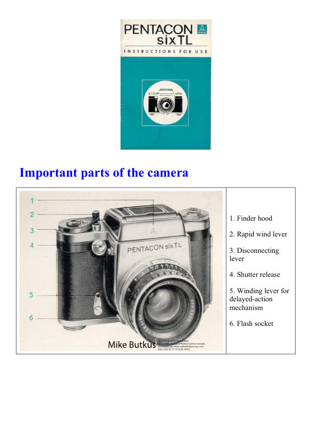
External view of the camera: Unfold the two inside pages of the front and back covers and look at
the camera itself in the same position as it is shown in the pictures of the instruction booklet. The
important parts are marked by numbers and explained on the page.
View original page 4Page 5 · Read text
www.butkus.us

Abridged Instructions
The following Abridged Instructions are a summary of the most important sections of this
Instruction Booklet. These sections deserve particular attention. Yet the knowledge acquired by
reading them alone cannot compensate for the valuable information to be obtained by studying the
complete instruction manual.

1. Pull latch (7) downward and open camera back. Exposure counter (17) jumps to starting point.

2. Place film into left-hand spool chamber.

3. Remove gumstrip pull paper leader across picture gate and push it into longer slit of the
receiving spool.

4. Swing rapid wind lever (2) around as far as it will go and continue advancing the film by small
rocking movements until the reference mark imprinted on the paper leader stands against the white
dot on the picture gate. Now move the rapid wind lever (2) back to its initial position and close the
camera back. The short rocking movements of the rapid wind lever may be performed only while
the film is being inserted, i.e. as long as the camera back is open, or after the 12th exposure.

5. Set film reminder dials (12 and 16).

6. Release the shutter and wind it again four times. The rapid wind lever must be swung without
interruption as far as it will go and moved back. The exposure counter (17) shows the mark for
picture 1.

7. Employ viewfinder image for focusing. Critical focusing is performed by means of the
magnifying lens.

8. After the 12th and (in case of roll film 220) the 24th exposure, the winding mechanism is locked.
It is released by means of disconnecting lever (3), whereupon film transporting can be continued.

9. In case of premature removal the film has to be wound up to the end with the paper trailer by f u
11 swings of the rapid wind lever and subsequent releasing of the shutter. Short rocking movements
of the rapid wind lever must not be performed before the 12th exposure has been made.
 (see also Section 4).


Inserting and advancing the film

Inserting the film starts with the unlatching and opening of the camera back. Any type of
commercially available roll film 120 for 12 exposures 6 x 6 cm (2 1/4 in. square) or roll film 220
for 24 exposures 6 x 6 cm (2 1/4 in. square) may be used in the camera. The film is inserted as
follows: Retract the two spool supports (8), rotate them to fixed position, place an empty intact film
spool into right-hand spool chamber, making sure that the carrier mechanism catches the spool
core, unlock the spool support and let it spring back. The pivot pin will engage in the spool core.
View original page 5
Page 6 · Read text
The full film spool is inserted into the left-hand spool chamber in exactly the same manner. First
swing rapid wind lever (2) around as far as it will go, then continue advancing the paper leader by
short rocking movements until the reference mark imprinted on it stands against the white dot on
the picture gate. Taut and even winding of the paper leader is necessary to avoid faulty film feed
periods. After this, move the rapid wind lever back to its initial position. Close the camera back. It
is of special importance to note that the short A rocking movements of the rapid wind lever may be
performed only while the film is being inserted, i.e. as long as the camera back is open, or after the
12th exposure.

To achieve faultless advancement of the film, special attention must be paid to the following 3
points:

1. Remove the gumstrip and insert the paper leader carefully into the middle of the spool. It must
not brush against either one of the spool flanges (Fig. 1). If this happens, the film will not advance
properly. There is even the possibility of the receiving spool getting jammed within the spool
chamber because of the irregular winding of the film, and the film transport mechanism might be
overstrained on actuation of the winding lever.

2. The paper leader, when being wound up, must lie tautly on the core of the receiving spool. This
can be achieved by slightly suppressing the movement of the full spool on the supply side with the
thumb of the left hand (Fig. 2). Make sure that the paper windings are not too loose on the take-up
spool (Fig. 3) since this might cause overlapping or excessive spacing between frames. The first
exposure could, in such a case, be made before the film is in the picture gate;

3. The short rocking movements of the rapid wind lever when advancing the film, which are
mentioned in this instruction booklet, may be performed only under the following conditions:

a) when the film is being inserted, as long as the camera back is still open, and

b) after exposure of the 12th frame and subsequent release of the locking device to permit further
advancement of the film.

Thus, if for instance a roll film 120 is to be removed from the camera after the 10th exposure, the
shutter has to be wound and released normally up to the 12th frame. Then, when the locking device
of the transport mechanism has been released, the film can be wound on to the end by short rocking
movements. In this manner you may also advance any 220 roll film after the 13th frame by rocking
it to the end.
View original page 6
Page 7 · Read text
www.butkus.us

Exposure counter


The exposure counter (17) jumps back to its
starting point when the camera back is opened and
is automatically set when the camera back is
closed. The shutter has to be released and wound
again four times, whereupon the mark for picture 1
will appear in the exposure counter. Do not let the
winding lever jump back but move it back
smoothly. At every subsequent winding of the
shutter the counting mechanism advances to the
next number. After the 12th and, in case of roll
film 220, after the 24th exposure, the winding
mechanism is locked. It has to be released again by
actuation of disconnecting lever (3). The rapid
wind lever can then be fully swung around again
steadily and without interruption.

Film reminder dial


Film reminder dial (12) bearing the symbols
for black-and-white and color film, is
mounted above the speed setting dial (13).
The symbol required is set for roll film 120
against the numeral 12 and for roll film 220
against the numeral 24 on the speed setting
dial. A second film reminder dial (16)
marking the film speed in DIN and ASA
readings is positioned above the rapid wind
lever.


Finder hood


The finder hood (1) opens and
springs into operating position
as soon as you push knob (9) in
the direction of the arrow. It is
closed by finger-tip pressure an
the cover. The finder hood is
automatically locked on to the
camera. To remove it, depress
unlocking knob (11) on the
camera top. The hood can then
be pushed towards the back and
lifted off.
View original page 7
Page 8 · Read text
Magnifier- Sports finder


The magnifier in the finder
hood is designed for critical
focusing | and to facilitate
picture composition. The
magnifying lens (14) yielding a
fourfold enlargement may be
swung into position. The
magnifier in the finder hood is
designed for critical focusing |
and to facilitate picture
composition. The magnifying
lens (14) yielding a fourfold
enlargement may be swung into
position parallel with the image
field lens. The sports finder is
moved into working position by
lifting the inner part of the
finder hood cover and pulling
out the frame (10).

Pentaprism


The Pentaprism permits viewing the image
at eye level. It is inserted in place of the
finder hood. The reflex image then appears
with sides unreversed and enlarged
approximately 2.5 times. Persons with
faulty eyesight may insert a corrective lens
into the eyepiece of the viewfinder to
replace their spectacles. You pull the two
lateral catches simultaneously towards the
back and place the pentaprism on the four
connecting pins on top of the camera, then
release the catches, and the pentaprism
snaps in. Removing the I prism is
performed accordingly.

TTL Prism--please refer to "Accessories".
View original page 8
Page 9 · Read text
www.butkus.us


Focusing


Focusing takes place with the
mirror swung into viewing
position, i.e. with the shutter
wound up. Rotate focusing ring
(22) on the lens mount until the
image of the subject appears
sharp on the field lens. Distance
and definition may also be set
by means of the scale on the
lens mount, in which case the
field lens serves only for
determining picture
composition. The depth of
definition can be read from the
focusing ring with the help of
depth-of-field scale (21).
Engraved on the left and right
of the index mark on the depth-
of-field scale are diaphragm
numerals. At the f/8 setting, for
instance, the depth of sharpness
can be read from the focusing
ring between the two diaphragm
numerals "8" on the depth-of-
field scale.

III.: Distance 5 m (17 ft.),
diaphragm setting f/8, depth of
sharpness 3.5 m to approx. 9.5
m = approx. 11 1/2 to 30 ft.

When using the sports finder,
focusing has to be performed
beforehand, either on the image
field lens or by the scale of the
focusing ring.
View original page 9
Page 10 · Read text
Image field lenses


7 different image field lenses are
available for the PENTAGON six
TL (see also the Instruction Booklet
describing ,,Close-up Equipment for
PRAKTISIX and PENTAGON
six"). The field lenses are exchanged
as follows: Remove the finder
element from the camera and then
loosen the screws on the three
retaining springs with a screw
driver. Swing the springs aside, take
out the spring ring, and tip the image
lens out of the camera. Fixing any
one of the other field lenses is
performed in reverse order. It is
important to note that the thinner
part of field lenses made of glass
must lie towards the back of the
camera. Please also note that
different supporting angle pieces and
spring rings are provided for the
Fresnel lens and for the other image
field lenses.

1. Groundglass field lens (Order No.
207250)
2. Groundglass field lens with clear
spot and hairline cross (Order No.
207330)
3. Groundglass field lens with
reticular guide lines (Order No.
207340)
4. Clear glass field lens with hairline
cross, 5 mm reticular (Order No.
207350)
5. Groundglass field lens with
hairline cross, 5 mm reticular (Order
No. 207360)
6. Groundglass field lens with
rangefinder wedges (Order No.
207370)
7. Fresnel lens with microprism
screen and Groundglass circle
(Order No. 207251)
View original page 10
Page 11 · Read text
www.butkus.us


Image field lens with rangefinder wedges (rangefinder lens)


The rangefinder wedges
correspond in effect to a split-
image rangefinder. The
rangefinder lens forms two part
images. These are moved
towards or away from each
other by rotation of focusing
ring (22). If the outlines join
precisely where the two sections
meet, the image is in correct
focus. This can be observed best
on straight vertical lines.
(7) Fresnel lens (see page 16).


Fresnel lens with microprism screen


The PENTAGON six TL can be                                                        Focusing with the microprism screen
supplied, as desired either with a
Fresnel lens for extra image brightness                                                            top picture- correct
and microp;ism screen, or with a
groundglass image field lens.                                                      bottom picture- incorrect

1. Focusing on the microprism screen

Correct focusing is achieved as soon
as the image in the microprism screen
looks clear and free from fuzziness.
The image is out of focus if it looks
fuzzy or crumbles into screen
elements. Focusing is extremely
reliable since you see very distinctly
the difference between sharpness and
unsharpness. Focusing should be
performed with the lens aperture wide
open (small diaphragm numeral).

2. Focusing on the groundglass circle

The circular groundglass screen is
used preferably in connection with
small lens apertures (large diaphragm
numerals) or in case of greater scales
View original page 11
Page 12 · Read text
of reproduction as, for instance, in
close-up or macro photography. The
remaining section of the viewfinder
(Fresnel lens) is not meant for
focusing.


The diaphragm


The diaphragm is set by rotation of the
diaphragm ring (20) on the lens mount The
diaphragm numeral required for the exposure
has to be brought to meet the red index mark.
Lenses with automatic spring diaphragm
allow for full aperture focusing. Not until the
shutter is released does the diaphragm close
down to the pre-set value. To check the depth
of field during focusing, you simply depress
lever (19) on the lens mount. This causes the
diaphragm to close down to the value
preselected by means of setting ring (20).


The focal-plane shutter


The focal-plane shutter of the
PENTAcON six TL gives exposure
speeds ranging from 1 sec. to 1/1000
sec. and B (any desired duration). For
exposure speeds of longer than 1 sec.
it is advisable to use a special wire
release with locking device. The
speeds are graduated so that each
figure indicates double, or one half of
the speed marked by the next figure on
the scale. The diaphragm scale works
analogously. If the light value is to be
maintained, the next smaller aperture
has to be employed for twice the
exposure time, or vice versa.
View original page 12
Page 13 · Read text
www.butkus.us

The exposure speeds


The exposure speeds may be set either before or
after the shutter has been wound. The speed
setting dial (13) is rotatable in either direction.
The desired exposure speed figure must come to
stand against the red triangular mark. The speed
settings click in as a safeguard against
unintentional displacement.


Rapid wind lever


The rapid wind lever serves not only to wind the
shutter but simultaneously to transport the film. By
this same performance the diaphragm is set to its
widest aperture, the exposure counter switched to
the next number, and the mirror swung away to
allow the light rays to reach the image field lens.


Delayed-action mechanism- Shutter release


The delayed-action mechanism is tensioned by swinging
the winding lever (5) through about 90 degrees and set in
motion by actuation of shutter release (4). The shutter
must be wound beforehand. The self-timer runs for
approx. 10 seconds. It may be employed with all shutter
speeds.

The shutter release is locked by turning the lower milled
ring (15) on the release knob (4) anti-clockwise as far as
it will go (the red dot must be at the top) Inadvertent
tripping of the shutter is thus made impossible. The
shutter mechanism is unlocked by turning the milled ring
back again.
View original page 13
Page 14 · Read text
Synchronization


Synchronization with electronic flash and flash
bulbs is effected by means of the X contact. The
flash socket (6) is built into the lower part of the
camera front. Clockwise rotation of the milled ring
on the flash socket keeps the flash plug locked in
position. When inserting or removing the flash plug
make sure that the red dot on the milled ring stands
opposite the red dot on the front of the flash socket.
For the use of electronic flash, the speed setting dial
must be moved to the (lighting bolt) setting, for
fast-burning bulbs to 1/15 sec., and for bulbs of a
longer flash duration to 1/8 sec. For delayed-action
exposures the shutter release has to be depressed
until the flash lights up. (Use cable release with
locking device). The correct diaphragm setting is
found by dividing the guide number of the flash by
the flash-to-subject distance figure.

Removing the film


Remove the film after exposing the 12th frame (on film 120) or the
24th frame (on film 220) and subsequently winding up the paper
trailer. To achieve this, first actuate disconnecting lever (3) and then
turn the rapid wind lever with full 11 swings followed by release of
the shutter, or carry out short rocking movements, until the winding
of the lever becomes noticeably easier.

This means that if a roll film 120 is to be removed from the camera
after the 10th exposure, the shutter has to be normally wound and
released up to the 12th frame.

Then, when the locking device of the transport mechanism has been
released, the film can be wound on to the end by short rocking
movements. In this manner you may also advance any 220 roll film
after the 13th frame by rocking it to the end.

Now open the camera back, pull out the spool support and lock it in position. Tip the spool with the
exposed film into your hand and fasten the paper trailer with the gumstrip. Should the camera be
firmly connected to any other equipment the film spool can also be removed by means of its lower
flange.
In this case, the spool must still be resting against the upper part of the spool chamber, i.e. engaged
by the carrier mechanism.
View original page 14
Page 15 · Read text
www.butkus.us

Exchanging lenses


Exchanging lenses is a quick and simple matter.
Turn milled ring ( 18) of the bayonet fitting anti-
clockwise (as seen from the front) until it stops
and remove the lens from the camera. The red
mark on the scale of the lens to be inserted must
be a the top, and the screw, or pin, on the inner
edge of the lens mount has to engage in the
recess in the lens seat of the camera (see
illustration). To fasten the lens tighten milled
ring (18) by clockwise movement (as seen from
the front).


Lenses


The standard lens, Zeiss Biometar 80mm f/2.8
is equipped with automatic spring diaphragm
control (ASD). No specific handling of the
lens is necessary except setting the aperture
required for the exposure. The diaphragm is
automatically controlled by the camera.
During the focusing procedure it is
completely open

Supplementary lenses with automatic
diaphragm are operated in the same manner as
described above for standard lenses. This
applies both to setting the diaphragm stop and
to checking the depth of field.

Supplementary lenses without automatic
diaphragm

(e.g. PENTAGON 300 mm f/4 with manual
pre-set diaphragm) are set by pressing the
setting ring directly behind the diaphragm
scale towards the back and adjusting it to
bring its mark against the desired diaphragm
numeral, where it clicks in. This makes it
possible also with these lenses to focus at full
aperture. Immediately before making the
exposure, you turn the diaphragm ring back to
the preselected stop.
View original page 15
Page 16 · Read text
With lenses of a longer focal length (exceeding 300 mm) the automatic diaphragm lever in the
camera may project into the path of rays and can, therefore, be moved away from its normal
working position towards the camera body. To achieve this, remove the lens from the camera and
swing the lever, which becomes visible on the left inside the opening, just far enough that it will not
touch the camera body when the shutter is wound. Swing the lever back into operating position
when lenses with automatic diaphragm are to be used.


Interchangeable lenses


The following interchangeable lenses are
available for the PENTACON six TL:

Standard lens Zeiss Biometar 80 mm f/2.8
ASD

Supplementary lenses:
Zeiss Flektogon 50 mm f/4 ASD
Zeiss Biometar 120 mm f/2.8 ASD
Zeiss Sonnar 180 mm f/2.8 ASD
PENTAGON (Orestegor) * 300 mm f/4
PD
PENTAGON (Orestegor) * 500 mm f/5.6
PD
Zeiss Spiegelobjektiv (Mirror Lens) 1000
mm f/5.6
ASD = automatic spring diaphragm
PD = pre-set diaphragm

* The lenses hitherto listed under the
name of Meyer Optics no bear the trade
name PENTACON.
View original page 16
Page 17 · Read text
www.butkus.us

Accessories for the PENTACON six TL


TTL Prism Attachment

An outstanding advantage of the PENTAGON six
TL is its ability to accept the TTL Prism Attachment
which can be used instead of the finder hood or the
ordinary pentaprism. It enables partially integral
light metering to be performed, based on the
modern, technically accurate internal measuring
system. All factors making any difference with
regard to the exposure are automatically taken into
account. Correction of exposure values as, for
instance, in close-up work or with filters, is no
longer necessary.

For further information please refer to our brochures
and to the instructions for using the TTL Prism
Attachment.


Equipment for close-up work

Set of Intermediate Rings
Set of Intermediate Rings with Plunger
10 mm Intermediate Ring with Plunger
Clase-up Bellows Attachment
Reversing Tube
Special Intermediate Ring with Cable Release Connection
Double Cable Release
Special Image Field Lenses
Focusing Magnifier

For further details please refer to our brochures and to the instructions for using
"Close-up Equipment for PENTACON six and PRAKTISIX."
View original page 17
Page 18 · Read text
Accessories for the connection to the eyepiece - accessory images


Additional Accessories


The following accessories may be attached
to the eyepiece of the pentaprism and of
                                            Special Pressure Plate for the use of
the TTL Prism Attachment:
                                          photographic glass plates
                                        Focusing Side
Eye Cup
                                           Universal Tripod
Focusing Telescope
                                                   Filters
Angle Finder
                                      Lens - Hoods
Mount for corrective lenses
                                        Cable Releases
Attachable Accessory Shoe

                                 One final hint with regard to setting up the
For further details please refer to our
                                      camera on a flat surface. A screw (Order
brochures and to the instructions for using
                                  Number 223650) to be threaded into the
"Eyepiece Attachments".
                                              tripod socket of the camera may be used as
                                          a third supporting


The details given in this booklet are subject to slight alterations which may result from further development in the manufacturing Process.

Please read these Instructions for Use carefully, since we can accept no liability for damage caused by improper handling of the camera.
View original page 18Related documents and language editions
From the M. Butkus archive. Original publisher and archive notices are retained.
Check the model and edition against your equipment.
PDF verified 2026-10-10.