Sewing machines
Pfaff A B - English — User manual
User manual for Pfaff A B - English. 24 pages in English. Read the original PDF, download or print a copy without registration.
24 pagesEnglish3.0 MB PDF
Loading your manual…Open PDF directly
Document details
- Brand
- Pfaff
- Model / document
- Pfaff A B - English
- Document type
- User manual
- Language
- English
- Pages
- 24
- File size
- 3.0 MB
- Category
- Sewing machines
- Document date
- Not specified in catalog
Contents
Search available document text
Find a term, then jump to its page in the original PDF. Image-only pages may not be searchable; check the PDF for exact wording and diagrams.
Page 1 · Read text
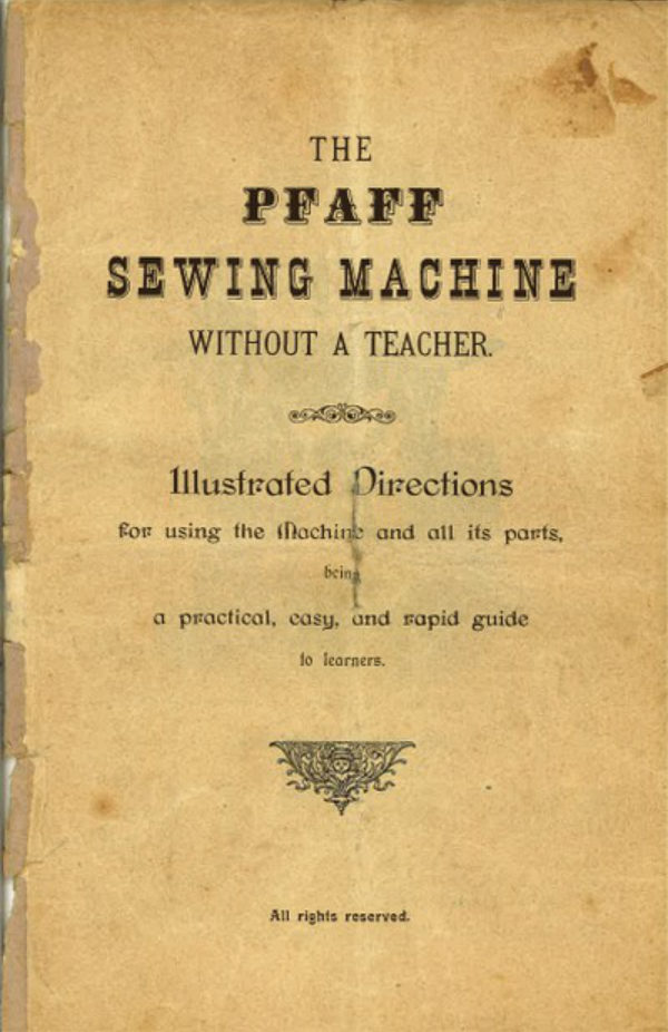
THE
   PFAFF
SEWING MACHINE

     WITHOUT A TEACHER.


    Illustrafed Directions
 for using the (Rachine and all its parts,

                           being
  a practical, easy, and rapid guide

                          fo learners.


                          All rights reserved.
View original page 1Page 3 · Read text
- 3 -

          Directions
        for using the Machine.


         A. Special Notes.
    The Pfaff Sewing Machine can be supplied as a Treadle
 Nachine, Fig. 1: as a Hand-achine, Fig. 2: or as a Hand and
 Creadle lachine combined. Fig. 3
                   If a Treadle Machine Fig. 1,

has been purchased, the following points will have to be attented to.
      After unpacking the Machine, pull out the drawer a little and
remove the cover.
    The machines are all properiy mounted, threaded, and made
 ready for use before they are sent out; but before commencing to
 sew, it is absolutely necessary first to acquire thorough expertness
in the practice of the
                Treadle-Motion.

     To save the wear of the machine in this preliminary
stage disconneet the upper fly-wheel of the machine in the
manner described on page 6.Draw the chair close up to the
machine, and place the right foot upon the treadle, so as to
exert the same amount of force with heel and toes while the
 treadle is being worked. Then use the right hand to set the upper
fly-wheel in motion, turning it in the direction towards you,
and keep it going, gently working the treadle. In the next place
 practice in the same way with the left foot and then go on to
 use both feet.
    Do not practice anything else, until you ean manage
to start the machine steadily and slowly, to stop it at will
and to again set it in motion without once doing it the
reverse way.
      After a while, the driving band may possibly become relaxed,
thereby interfering with the running of the machine. In that case
the band should be taken asunder and shortened by cutting off a
 small piece with a knife.
         If after long use a new belt is wanted, one of exactly the
View original page 3Page 4 · Read text
- 4 -

same thiekness should be bought, as a thicker belt cannot be used
on the machine.
    The fy-wheel and wooden pitman of the stand are so desig-
ned and put together, that, if rendered somewhat slack with wear,
they may readily be steadied again by means of wrench aud serew-
driver.
      The new improved treale runs always closely and verysmoothly.
     The fly-wheel has a curred steel-erank and runs upon harde-
ned steel-centres.
    The stand must be constantly kept well oiled at both sides
of the foot-plate, at both ends of the wooden pitman and at the
points of the fly-wbeel axle-pin.

wheelThisframenewthatimprovedin made.stand forms the smoothest running fly-


                      If a Hand-Machine Fig. 2,

has been purchased,


                         Figure %

first let it be unpacked, and then unlock the cover andremove
    In the nextplacepull out the disconnected handle of the
 driving apparatus, and fit it on to the machine by meansof the
     working spring-catch.       connect the upper fly-wheel,
   described on page 6,                be commenced at
once, as the machine is sent out from the Works properly mounted,
threaded, and ready for use.
     The Driving Apparatus must be constantly kept well oiled.
View original page 4Page 5 · Read text
— 3

If a Hand and Treadle Machine combined, Fig. 3,


                             Figure S.

 has been purchased, first get it unpacked, then unlock and remove
 the corer.
      Then pull out the disconnected handle of the driving apparatas
  and fix it on by means of the easy working spring-catch. By
  aking off the band from the fly-wheel and by pushing the spring
  joint of the moving cum between the spokes of the upper fly-wheel,
  the machine is converted to a Hand-Machine, which can be taken
  off the stand and worked on any other table.
            If the machine is to be used as a Treadle Machine the band
  must be put on again,care being taken that it does not graze

  against any part along its course.
        As regards the treadle motion, again refer to the directions

  given on page 3,
     When the machine is to be used as a tigadle machine, see
   to it, that the moving cam of the hand apparatus which links on to
View original page 5Page 6 · Read text
6

the spokes of the fly-wheel, is first detached; otherwise the operator
cannot avoid breaking the hand apparatus.


       The Driving Apparatus must always be kept well oiled.

      NB. Before leuving the factory, every Pfaff Machine is sub-
jected to a test so severe,that a heavy running Pfaff Machine is
made imposible. If notwithstanding a machine runs heavily it
 must be owing to insufficient oiling and eleaning. - Careful
 attention should therefore be paid to the instructions for oiling and
 leaning given on page 18 of this book


           B. General flotes.
(Applicable to every description of Pfaff B, C & D Sewing
                          Machines.)
      The Disconnecting of the Fly-wheel
previously referred to on page 3, is accomplished in the following
 simple manner.
      13                             Pull out the stud 1 Pig. 4
                             onthe fly-wheel, turn it round
                     a little,until the small
                                   rests on the projection of the
                                Ey-wheel. When the machine
                         18 to be put in gear again,
                                  turn round the stud unti. the
                                smallAtpinthisslipsstageinto theit willslit.be
                                    necessary  to acquire profi-
                               ciency in the
                            Guiding of the
                                   Material.


                                         First remove the fabrio and
                                 to do tbis, it will be песев-
                                    saryhighestto liftattainablethe needle to the
                              turning the upper ty-whool,             Figura 4.          and to raise the presser-lever
     Disconneeting the upper   20 (Fig. 5). In the place of
          Fly-Wheel.          the fabric 80 remoTed,nOW
View original page 6Page 7 · Read text
insert a piece of cloth or paper; lower again the foot 22, by

 alceseansoutofthetheshuttle.presser lever;The latterdrawoperationthe threadis outmateriallyof the needlefacilitatedan
by the use of the new
                                             Shuttle Ejector
                                         on ope-                                              which,
                                              ning the slide 19
                                         (Fig. 5) onthe
                                       lefthand side,
                                                   will so raise the
                                                      shuttle out of its
                                                box assto enable
                                            one to get hold

                                                       of it with perfect
                                                    ease.  Now com-
 mence to set the machine in motion. Guide the material first along
 straight lines, previously  traced,  and afterwards along curved
                                           lines, at the same time taking
                                       care not to drag it or to shift
                                                     it from its course.
                                  The setting of the machine
                                   for
                        Long or Short Stitehes

                                                is accomplished by means of
                                         the Stitch-Regulator-Serew &
                                     (Fig: 4). if turned a little


                                      outwards       and pushed


                                               to the right, the stitches will be
                                         longer: if pushed to the left,
                                     thestitches will be shorter.
                            When the desired length
                                           of stitch has been obtained,
                                         the Stitch- Regulator - Serew
                                       must be made fast.

                                            Now take hold of the upper
                                         thread, bringing it from the
                  Figure 6.             reel revolving upon
                                          spindle 9, and pass it first
   View of the Pfaff machiue from through the ring 10, next in
  abore showing the insertion of the between the tension dises 11,
            upper Thread.         as shown on the engraving
View original page 7Page 8 · Read text
ie e eye of the celly m the ront che honk trongh the

eye of the needle.
              To Thread the Shuttle.


                            Figure 6.
     Take the shuttle in the left hand. holding the pointed end
 towards you. Press the small braas disc of the bobbin, which lies
 near the point of the shuttle, with the forefinger of the right hand
 in the direction of the point of the shuttle.  This will cause the
 bobbin to be jerked out.
       To replace the bobbin in it one end of it into the centre of
 the spring-catch at the pointed end of the shuttle, then press the
 other end of the bobbin gentle down until it locks into position
                                Place the bobbin so,that the
 withthreata shallslightcomeringingupwardssoand.from the under side of the bobbin on
 that side of the shuttle which has two long slits. Pass the thread
 (as shown in figure) down the ait and round the end of the bar a,
 draw it across the bobbin down the slit b and towards the point
 of the shuttle.
     Then draw it down the slit e and towards the broad end of
                                         the loose end of the the shuttle, and finally paas itunderneath outside-spring at the broad end of the shuttle, which will now be
 ready for use.
      To regulate the tension of the shuftle use the small shuttle-
 screw-driverscrew d to thespeciallyright to tightenprovidedthewithtensionthe machine and tarn the

                    left to sincken
     The points of the bobbin should be slightly oiled from time
  to time.
     The Filling of the Bobbin is effected by meansof the Plaff
 Universal Winder.
     The Pfulf machines are invariably sent out with the winder
 threaded and a bobbin half filled on it.  Let the arrangement be
  attentively stelied before attempting to use the winding apparatus
 and the following description will the more easily be understood.
View original page 8Page 9 · Read text
- 9 -
                                Havingfinit disconnected
                               the fly-wheel of the machine

                                   in the manner before described,
                                 one of the small bobbins must
                                  be placed with both its points
                               in the winding apparatus, 38
FF                               plainly shown in Fig. T, using
                              the left hand to pull back the
                                  pring - catch for the purpose
                                    In this operation care should
                          be taken that the small pin in
                                the bobbin dise of the winder
                                 catches in the hole of the small
                               brass dise of the bobbin.
                          The reel from which the
                                 shuttle bobbin is to be filled,

                             should3. whore.he put an be he ater
                                 the winding is over; then pass
                                  the chread. as shown in Fig. 1,
                                   into the wire ring 4 fitted on
             Figure 7.            the belt guard, then from the
 The Plaft Universal Winder. front in between the two tenaion
                                 disca 5, thence into the upper
notch of the thread guide-rod 6, an lastly into the other notch on
the same rod, situated somewhat Swer and to the right.

insertion of the thread is even easier, if performed in a reverse
order of sequence. By pulling the hobbin with the left hand some-
 what to the left, the end of the thread ean be placed between the
 small brass dise and the winder dise, and theré held fast. After
 pulling in the slack of the thread by winding it back again on to
 the reel, press the winder so firmly against the fly-wheel by means
 of the lever ftted on just below the winding apparatus, that it
 may no longer fall back but commence winding when the fly-wheel

 is set in motion in the ordinary way.

 ThreadTheguide-rod,thread willand glidewill windover itselfthe highlycloselypolishedaroundtrackthe bobbin.of the

       So soon as the bobbin has been sufficiently filled, the winding
 apparatas will disconneet itself automatically.This self-acting
 disconnection arrangement will enable one to fill a bobbin while
 the machine is sewing.  But it is nevertheless preferable to fill the
 bobbin as a distinct piece of work, because sewingand winding
 at one and the same time will as a matter of course always render

 the action of the machine heavier.

       If during the process of winding, the thread should accidentally
 give out, ere the bobbin has ben completely filled, it will be
View original page 9Page 10 · Read text
- 10 -

 necessary to press back the thread guide-rod until the winder drops,
 or else the bobbin cannot be taken out.
         If the rubber ring should get so far worn, that it is no
 longer fit for use, and must be replaced by a fresh one, pull the
 thread carrier-bar towards you andthe new ring can then be put
 on with ease. That done, return the thread carrierbar to its former
 position.

       Every, part of the winding apparatus liable to friction should
 always be kept well oiled.

                 The needle

 in inserted in the followingmanner. Raise the needle-bar to its
highestpoint,loosen the needle-clamp acrew 17 (Fig. 5) with the
 right hand, and take out the needle  The needle has a long groove
on one side and a short one on the other.  Take it between the

thumbthe longand grooveforefingerto faceof theyou,leftguidehand thein suchblunta endmannerof asthetoneedlebring
 under the needlo-clamp 16, into the needle-slide, and with the right
hand tighten the neodle-clamp sorew 17.

      Thereupon turn the needle-bar dowawards until the notch
upon the needle-bar (the needle-gunge-mark 18, Fig. 5) is in a
line with the upper surface of the head plate, loosen the needle.
clamp and so fix the needle that the eye of the needle shall be
level with the upper surface             Having finally
ascertained that the oye stands true and straight, tighten the needle-
clamp-serew again.
     Bent or blunt needles should never be used.
    The character, quality, and proper position of the
 needles are of the highest importance as resards the effi.
eleney of the machine. If the machine should at any time
fail to work quite faultlessly, let the needle be examined
at once, and, as a rule, the defect will be speedily remedied.
     In working the Pfaff Machines only Pfall Needles with the
name Pfaff" on the blunt end should be used viz:
      B Needles for Pfall B Jachines
    *C&D   19  "  " C&D
    The thickness of the needles has always to correspond with
that of the thread, as thin needies with thick thread cause the
leaving out of stitches, while thick needles with thin thread cannot
produce fine seams. Choose therefore your needles according to th
  lirections given on page 24

      After thresding the needle, open the alide 19 (Fig. 5), lay
     huttle in the shuttle-box with its point towards the needle.
         flat spring-bar uppermost.
View original page 10Page 11 · Read text
- 11 -

                                        Before commencing
                                     to  sew,  the  shuttle
                                       thread must be brought
                                up through the needle
                                                  plate.  This can  be
                                 done by firmly holding
                                 down  the  apper
                                       reel thread,with the
                                               forefinger of the left hand
                                    as shown in cut (Fig. S),
                                        whilst the Hy-wheel is
                                     turned once round with
                                     the right hand, until                                  the needle har ngain
                                         reached its highest point.
                             Now use the screw-driver
                                 or any other suitable
                                             article to whisk  out
               Figure 8.             from under the presser
                              foot the1oop, of the    Drawing up the under thread.                                     underthread which will
                                  have come into view by
                                   twothis threadstime, andto thelaybackthe
                                        of the needle.

                                         materialterre pom place the
                                      presser foot, lower the
                                        Intter br means of the
                                      lever 20 (Fig. 5) and


                              To Sew.

                             When sewing  OVeT
                                           thick hard places, turn
                                 the fly-wheel  gently
                                       with the hand, to pre-
                             went the bending or
                                      breaking of the needle.
                Figure 9.                                 To sew sharp corners,
        The Threadeutter.            let the needle remain
                                         in the material,  raise
the foot by means of the lever and turn the material round about
the needle, whereupon the lever maybe lowered again.  If after
completing the work, it be desired to withdraw the maserial, raise
the needle, lift the presser foot, pull out the material and snip
View original page 11Page 12 · Read text
- 12

 Fig.off the9. thread against the thread-cutter, as shown in the eograving,

    The pulling out of the material may never be done
 towards the operator, but the threads must be drawn ont
 always under the presser-foot from behind.
     This point will have to be curefully attended to benute
 otherwise the needle will be bent or will come in contaet with the

readed fromit ne thenequenceshuttle isofnowhichloogerthesureneedleto catchbeingthe tooloopfarof
 the thread; in that case the machine will leate out stitches or the
 needle will break.
     To obtain a faultlesa lock-stitch, see to it that

               The Tension
 is always properly regulated, which means that the tension of the
upper or needie thread shall invariably be as strong as that of
 theshuttle thread. As regards the degree of ténsion of shuttle
 thread, enough has been said in the preceding pages.
    The tension of the upper thread is regulated by means of
 the tension-screw 21 (Fig. 5). If this screw be turned inwards

       the thread will tightens und if outwards it will on the con-


                         nwards and will form small knots

    Whereas if the tension iritoo great, the shuttle thread will
be dragged upwards, or else the needle thread will break. Thick
fabrice require a greater amount of tension on both the needle and
the shuttle threads, than less heavy goods.

                                                           Tbe tession of the
                                                          apperthread being
                                                             inserscarat or the
                                                              teasion of the
                                                             sauttie thread too
                    Figure 10.                          great

                                                           The tension of the
                                      t00apperthreadgreat orbeingthe
                                                             teasion of the
                                                            sbattle thread in-
                       Figure 11.                                     suffictent.


                                                           Upper and saattle
                                                               thread properly
                                                                   regulated   3E3038
                      Figure 12.
View original page 12Page 13 · Read text
- 13 -

            If the machine be used daily, it should also be

                Oiled and Cleaned

 every day. To oil the machine the oil-can supplied with it is
  used, firat filling it with oil after unserewing the nozzle. The
 holes that need oiling are numbered 1, 2, 3, 4, 5, 6, 7, 8, 9, •
 10, 11, 12 and 13 on the annexed engraving (Fig. 13). Through
 the hole No. 2, oil is applied to the most important part
 of the machine — the heart of it — by turning the fly-
 wheel until a bright eylinder comes into view within the
 said hole, upon which a few drops of oil should be poured.
 The needle bar too, No. 6, as well as the check lever No. 4 & A

  must be constantly kept well eiled.


            PFARE


                             Vigure 18.

The machine viewed from abore and showing the parts which
                 should be lubrieated.

      In order to reach and oil the parts exposed to friction below
the plate of the machine, first remove the band from the wheel
on the stand, take out the fastening serew before the stitch regulator,
turn back the upper part of the machite, as shown in Fig.14.
and then oil every one of the spots marked with the figures 12;
15, 16, 17, 18 and 19.
View original page 13Page 14 · Read text
- 14 -


               18


                     Pfaff


                             Figure 14.
Underneath view of the Pfall machine showing the parts
              which should be Inbricated.

      Oil the treadle through the holes No. 1 and 2, the pitman
through the holes No. 3 and f and the fly-wheel crank through the
holes No. 5 & 6.
                                                    If from long  disusethe
                               parts of the Stand are a little
                            worn out and the stand makes
                                  a knocking noise it must be
                             adjusted on the pieces of the
                                 treadle marked No. 1 and 2, also

                           on the pitman screws marked
                         No. 3 &4 and on the piece
                          marked No. 6. - The moving

                               parts must have no air in their
                                   earings but they must nevertheless
                               move very easily.
                          Itoften happens thatthe
                              parts of the Stand are screwed
                      too fastin  consequence  of
                              which the machine in not light

                               running.
                                      If from long disuse the Machine
           Figure 15.         should work stiffly, put a little
   The parts of the stand   petroleum on the parts above
 which should be lubricated. named, let the  machine run
View original page 14Page 15 · Read text
- 15 -

 empty some revolutions so that the petroleum may spread and dissolve
 the oil that has set hard.
     The petroleum should be kept in a separate oil-can.

     The machine will now run freely; bat as petroleum will very
 soon evaporate, good machine oil should at once be applied to all
 the parts. After oiling, carefully wipe the machine cleun where
 necessary, to obviate the soiling of the needlework.

 shouldThe bebestboughtmachineat theoil isestablishmentthe pule SpermwhereOil,thewhieh,machineif possibleitself
 has been purchased.


             Hemming, Braiding ete.

 should not be attempted before thorough profeieney in ordi-
                                         nary sewing (running)
                                        with the Machine has
                                       been acquired. The
                                            various  fittings  for
                                              other work are so care-
                                           fally  described  and
                                          securately depicted in
                                                following
                                          that learners willeX•ex-
                                           perience no dithculty
                                                  in the use of them.
                                 Inorder that any
                                            particular small foot-
                                      apparatus may easily
                              be found bylearners,
                                         this  instruction - book
                                          contains the numbers,
                                    which are stamped on
                 Figure 16.
  The narrow and the wide hemmer.  each small foot.

             (No. 1 & No. 2)

         The Narrow Hemmer. (No. 1.)
     Take away the ordinary Sewer-Foot and adjust the Hemmer
instead. Bringone end of the fabric into the front part ofthe
spring spiral of the Hemmer as far as the needle, having first
turned in a length of about one inch to the required width of
hem. Lower the presser and commence to sew, taking care that
the material runs uniformly into the spiral, just as shown on the
engraving Fig. 16.
View original page 15Page 16 · Read text
- 16 -


      Soft, undressed fabrics present some difficulty when attempted

to run them into the spiral, and for this reason it in advisable to
draw the material into the spiral by means of a thread, previously
attached to the edge of it.
     This hemmer will also prodace a beautiful felled hem,and
that to such a degree of perfection,as no other Sewing Machine
as yet introduced has ever accomplished. Hor this purpose the two
 sortions of the material to be joined, should just as in hand-sewing
 se laid over one another and sown torether in such manner tha
the seam be kept at a uniforn distance from the edge  Now cut
the border of theupper cloth somewhat narrower, and pass the
border of the underneath material through the hemmer.
     This can be carried out with such accuracy that the Inbrie
need not even be guided.


           The Wide Hemmer. (No. 2.)

     This is used in the same wayas the narrow hemmer just
described. It is an excellent Ruffle Hommer, and well adapteil for
hemming and felling course linen.
          The Adjustable Hemmer.
    Fix the Hemner, as shown in Fig-17, by means of the
                                       thumb-serew  supplied
                                       with the Machine.To
                                           introdace the material,
                                          turn in the edge at the
                                    commencement for a
                                            lengthto theextentof about 5ofincheshalf

                                       the width of the hem.
                                     Push the folded portion
                                       sideways   into  the
                               hemmer, so that the
                                         folded edge shall turn
                                   up once more as wide
                                   as the hem. Place the

                                              material properly under
                                         the needle, lower the
                                                 foot,  and   ect  the
                                  Machine in motion. If
                                      the seam should not
                  Figure 17.              be running in the right
      The adjustable hemmer.         direction, the thumb-
                                 serew must be uns-
View original page 16Page 17 · Read text
- 17 -
crewed, and the hemmer shifted to the right or to the left, to
bring the seam into its proper place
     In order to set this hemmer for hems of varving widths,
slightly loosen the serew in theslit of the hemmer, which will
render the graduated slite adjustable.
     The narrowest hem will be produced by setting the index
 trainst zero; the higher it is set in the numbered scale, the wider
will be the seam. The screw must be tightened again before
commencing to sew.

             The Feller. (No. 3.)
    This is fitted on in the same way as the hemmer.  In
          felling, the two pieces of material, which are to be joined together,
                                       should be laid
                                      over the other in such
                               a way as to lot the
                                         underneath piece show
                                        to the extent of one
                                         sixth of an inch. Let
                             the
                              be inserted
                                                    feller in the same way
                                as in the cuse of the
                                  hemmer; and thus the
                                         underneath   material
                                              will be turned in once,
                                    and sewn on to the

                                            top piece.
                               Now spread out the
                                   two pieces joinedtO-
                                     gether as shown in
                 Figure 18.                Figure 18, smooth the
          The Feller.           sear and pass the
                     (No. 3.)                  brim which has formed,
  shown o0engraving, once more under the feller to sew it
over again.
              The Guide.

     This guide, as Fig. 19 shows, is madefast by means of
the thumb-serewsupplied,and serves to produce a seamthat
shall run even with the edge of the material. The guide should
be moved away from the needle according to the distance of the
seam from the edge of the material.  The guide can also be used
with advantage for rows of inside stitching by turning down the
View original page 17Page 19 · Read text
— 19


      In practice, a straight row of stitches must be run, follo-
       wing a line first chalked out. Then push the fabric to the right
 as far away from the needle, as the rows of stitching are to
stand apart.  Thereupon move the guide likewise to the righ
 ust far enough to bring its lower end exactly above the first rov
of stitching. In continuing the work it will be necessary to watch
 the material, so as to ensure the run of the stitching along the

gue forming of rocean the same way for the noxt row, and in
    The most perfect squares will be obtained if the material be
stitched on the wadding without lining or foundation.

         The Edge Trimmer. (No. 5.)
           This apparatus which is screwed on in the sameWaY 18
the preceding ones, is provided on the underside with a large
                                         groove.  After joining
                                   the material to  the
                                    lining by means of n
                                         single row of stitches,
                                      the two pieces are to
                                       be so spread out as to
                                        bring the right side of
                                      the material upwards.
                                      Then the cord is laid
                             under the groove of
                                             the presserfoot and care-

                                    fully sewn on to the
                                   seam, in between the
                                         material and the lining
                                        with rather long stit-

                                      chee. When the lining,
                              sewD over again,
                                      she cord will come to
                 Figure 21.                lie along the lower edge
     The Edge Trimmer. (No. 5)      of the material.


                The Corder. (No. 6.)
    The Corder, which is to be fixed inthe place of the
 stitcher, serves for sewing in cords on shirt collars, wristbands
 ete.  This apparatas hast two grooves on the underside for the
purpose of guiding the cord and at the same time pressing the
 material against the cord so as to bring out the work into bold
relief.
View original page 19Page 21 · Read text
- 21 -

 push the little slide of the attachment so far inwards that the
 braid is closed but that it nerertheless may be pulled easily trough
 the opening. Then the slide must be fastened by means of the
 little serew at the side.

       All that now remains to do is so to guide the work as to
 execute any kind of ornamental braiding required.

       Braiding design sheets for the Pfaff Machine are kept for salo
 at the establichment where the Machine has been bought.

      Cut out the pattera to be braided,

materialis easily Theremovedthe pattomewhen finished.to che tron the top opthe paper, which


              The Trimmer. (No. 8.)

                                    Thisis used for

                                          stitching ribbon at one
                                    edge fat against any
                                        material placed under.
                                      neath. It is fixed to
                                         the Machine in the same
                                     way as all the other

                                        attachments for special
                                    work.  The ribbon is
                                       carried in to the slit
                                         situated the right side
                                     of the Stitcher, the
                                            material is placed under-
                                       weath, and then sewing
                                     may be commenced, al-
                                     ways takingcure that
                                            the ribbon runs full into
                                     the slit aodis being                 Figure 24.
                                         sewn on to the material
       The Trimmer. (No. 8.)         in the proper direction.

            The Ruffler. (No. 9.)

smoothlying foldeand ofeven.Thematerialiafittingbeonte totedtheshitMachinethe loweris effectedof tre minein the

same way as in the ease of all the other special attachments. Bring
the material which is to be ruffled, as shown on engraving Figure
    25, under the apparatus upon the feeder, and that which is to
remain snooth over it, into the fissure of the apparatus. The feed
now will act only upon the under layer of cloth, while the upper
is being comparatively rotarded in its course between the two plates,
View original page 21Page 23 · Read text
- 28 -

     The Ordinary Sewing-Foot bears the Number 10 stamped upon
it.  In addition to all the special attachments before mentioned,
 the following extras are supplied with each Machine, viz.

  10 Assorted Pfaff Needles,      1 Strong Screw-driver,
   6 Bobbins,                      1 Strong Oil-can,
    1 Extra Stiteb-plate,           1 Wrench,
                                         1. Instruction-book.

     The Pfaff-Machine is fitted with the following improrements vix.
   1) Perfect noiseless motion,      6) TheThreading  of the
   2) The Plaff Automatic Win-           Needle- and Shuttle-
       der,                              threads by looping,
  S) The Shuttle Ejector,              7j The Tension-Disconnector,
   4) The new easy working         8) The Thread-Cutter,
        Stand,                       9) The Inch-measure seale on
   5) The Oil-can Rest on the          the table,
        stand                      10) The Foot Rest.

      All parts of the Pfaff Machine exposed to friction, such as
 the gear wheels,the shuttle, the feed ete., are forged out of the

 best steel, not of cast-iron.


             Conclusion.


      Should a Pfaff machine ever go wat of order and be in such
 a state that it fails to work faultlessly even if these instructions
 are strictly carried out, I request my customers to have the machine
 repaired only by the person from whom it hns been bought, or
 at the Factory.By no means the machine should be entrusted
 to unknown people because by so doing it often happened that such
 people have totally damaged the muchine either with the intention

 to do so or by ignorance
       Besides I have often experienced that thread too coarse is
                                                  It should
 usedbe bornefor sewingin mindeventhatlightthe Machinematerialssewson thewithMachine.two threads, and

 thatof thatconsequentlyused in handthe sewing.thread shouldThread,be asjustfineoneashalf80 andthe upwards,thickness
        may be used for any ordinary needlework; and if this suggestion
 is followed, the work with a fine noedle and with a proper tension
 will turn out very beautiful, and at the same time durable,
View original page 23Related documents and language editions
From the ISMACS International. Original publisher and archive notices are retained.
Check the model and edition against your equipment.
PDF verified 2026-10-11.