Film cameras
Rollei Rolleiflex 2.8 E User manual
User manual for Rollei Rolleiflex 2.8 E. 40 pages in English. Read the original PDF, download or print a copy without registration.
40 pagesEnglish3.1 MB PDF
Loading your manual…Open PDF directly
Document details
- Brand
- Rollei
- Model / document
- Rollei Rolleiflex 2.8 E
- Document type
- User manual
- Language
- English
- Pages
- 40
- File size
- 3.1 MB
- Category
- Film cameras
- Document date
- Not specified in catalog
Search available document text
Find a term, then jump to its page in the original PDF. Image-only pages may not be searchable; check the PDF for exact wording and diagrams.
Page 4 · Read text
Digitally signed by Mike Butkus
                                                                                                                       DN: cn=Mike Butkus, o=Butkus camera manuals,
                                                                                                                                    ou=butkus.org, email=mike@butkus.org, c=US                   Mike Butkus Date: 2023.05.17 16:01:35 -04'00'


As today's example of a practical precision camera, the Rollei offers not only the highest degree of
performance and optical quality, but also all the ease of use one could wish for. Just three controls
and three operations suffice for everyday use. Correct operation is simplicity itself. Because of the
virtues of its design and construction, Rollei easily copes with all the special tasks that the
photographer who wishes to take full advantage of his and its capabilities will set himself.

The following pages constitute a detailed "Instructions for Rollei-Photography" and therefore will
be suitable even for later reference. The illustrations will quickly acquaint you with the handling
characteristics and operations. Moreover, if you wish to get into photographic action immediately,
note that everything important is especially emphasized by arrows in the fallowing abstract.

Page                     Page                     Page

6. I. A Brief Rolleiflex.       24. Light Value (shutter      44. V. Tips on Picture Taking
                           speed and diaphragm
Anatomy                   combination)                Tables:
                             26. Sharpness and Depth
12. II. Rolleiflex in            of-field                      22. Light Values
Operation                   30. Shutter Tensioning       23. Light Value and time Exposures
                             30. Releasing                25. Speed of Moving Objects and Shutter
12. Neck Strap               31. Self-Timer             Speeds
View original page 4Page 5 · Read text
www.butkus.us


13. Ever Ready Case         32. III. Flashlight            29. Depth of Field
13. Lens Cap              Technique                  34. Flash-Contact and Shutter Speeds
14. Holding the Camera      36. IV. Landing and Film     43. Speed of Emulsions
16. Focusing Hood          Transport                    55. Color Conversion Filters
16. Focusing Magnifier       36. Back                     56. Rollei Filters
17. Direct View Finder       38. Inserting the Film        58. Rolleinars
19. Exposure Meter         Spool                        59. Practical Accessories
20. Measuring reflected      40. Threading the Film
and incident light            40. Film Transport
                             43. Film Reminder


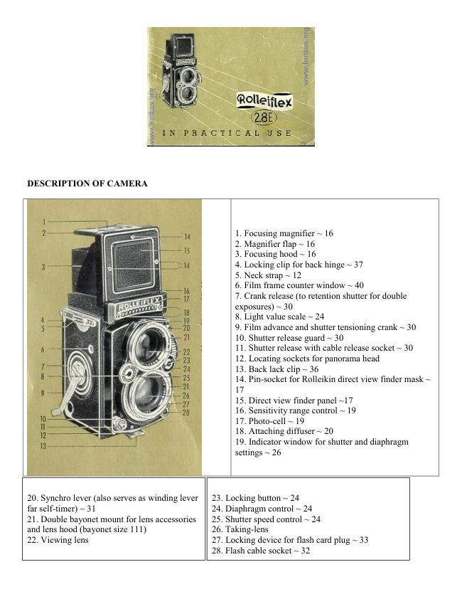
1. A BRIEF ROLLEIFLEX-ANATOMY


                                                 In the Rolleiflex two separate cameras are joined in a
                                            twin-camera with a common sturdy die-cast body:
                                                 the bottom half is the taking-camera, in which the
                                                film is exposed, and the upper half is the viewing-
                                             camera, which is designed on the mirror-reflex
                                                     principle. Its special task is to make the focusing
                                                    visible on the ground glass and to supply o control
                                         image essentially similar to that of the prospective
                                                     picture.

                                       The image forming rays are transmitted by the fully
                                         open viewing lens, projected on to the ground glass
                                               screen via the mirror and the result is a right-side-up
                                           ground glass image, in the full size of the original
                                                     picture. This viewing image is visible at all times
                                          and every detail of composition and framing may be
                                          watched even during exposure.

                                       The ground glass screen is ruled with a number of
                                                      vertical and horizontal lines making it possible to
                                                  detect errors, such as lines which converge but
                                             should be parallel or a slanting horizon, in time to
                                                 notice and correct them. It is easy to straighten or
                                                    level the camera by means of the lines on the ground
                                                  glass screen.
View original page 5Page 6 · Read text
Above all, the ground glass screen provides the
means for focusing the camera. This is accomplished
by rotating the focusing knob. Both lenses, which
are inflexibly coupled to each other by means of a
sturdy common front plate, are thereby adjusted
simultaneously a sharp viewing image therefore
guarantees an equally sharp picture. Since the
Rolleiflex is equipped with a fast viewing lens and
on optically prepared ground glass screen, the
viewing image is extremely bright and clear and
focusing can be done very critically.

The focusing hood, which is designed far one-hand
operation is kept in both open and closed positions
by spring tension. It is equipped with o swinging
magnifier. It offers at approximately 2.5 times
magnification of the entire ground gloss image, a
still more precise means for focusing the camera.

If the front panel of the focusing hood is pushed
inward,~ it is transformed into a direct view finder;
through which the subject may be seen in natural
size making it particularly easy to follow fast action.
In this case it is still possible at all times to maintain
control over focus this is mode possible by means of
a second magnifier in the back of focusing hood, and
a diagonally mounted mirror. A slight raising or
lowering of the Rolleiflex is all that is required to
alternate between the right-side-up open view in the
direct finder, and the reversed center portion of the
ground gloss focusing image. The fact that the two
finder openings are located so close together,
enables quick framing of the subject offer focusing.
The usefulness of the open direct view finder is
thereby enhanced for sports pictures.
View original page 6
Page 7 · Read text
www.butkus.us


Focusing the front lens panel throughout the range
from no (infinity) -- 40 inches (distances measured
from the focal or film plane to the subject) is
accomplished by nearly one full turn of the focusing
knob. The special design of the focusing mechanism
(a cam drive based on the principle of the
Archimedes spiral) insures uniform movement of
the lens panel in both directions without play or
backlash.

Tied in with the movement of the lenses is a simple
sliding mechanism, located beneath the ground
glass, providing completely automatic parallax
compensation. Consequently, the final picture is
always framed exactly as originally viewed an the
ground glass screen. Similarly complete control is
had even when using supplementary Rolleinor
lenses for close-up work because of the prism which
is built into the Heidosmat-Rolleinar.

The exposure meter is made up of the light sensitive
element, or photo-cell, in the name plate of the
camera and the measuring mechanism in the
focusing knob. It can be adjusted far two ranges of
sensitivity In brilliant light the photo-cell is partially
covered by an opaque shutter behind the honey
comb lenses of the photo-cell. In dim light the
photo-cell receives all the light coming through the
honey comb far full sensitivity. The reading is
supplied in the form of the light value far the film
speed being used. The light value can be obtained by
measuring the light reflected from the object or
scene, or the incident light, through the attachable
diffuser.

The Synchro-Compur-Shutter is adjusted
automatically for the correct exposure when set to
the previously determined light value. After this is
done the two controls (speed and diaphragm) may
be lacked together by the very simply operated
coupling button. Shutter speed and companion
diaphragm opening may thereafter be changed at
will, within the available range of operation, using a
single control and without altering the exposure.
Each speed-diaphragm combination appears, as the
control is turned, in the peep window in front of the
ground glass. When required the two controls may
be separately adjusted by merely uncoupling the
mechanism.
View original page 7
Page 8 · Read text
The depth-of-field indicator on the focusing knob is permanently
                              coupled to the diaphragm and indicates by means of a white band,
                                     that portion of the field which is in the actual range at sharpness

                               Since the two lenses are of identical focal length (f = 80 mm, picture
                                angle Across diagonal, 53°) it follows that the image in both
                                  sections of the camera will always be critically focused on the same
                                 portion of the subject simultaneously. The f :2.8 taking lens is a five
                                   glass construction with two cemented elements (modified Gauss-
                                  type) and features outstanding correction for black and white and
                                  color pictures, while the viewing-Heidosmat f 2.8 lens meets with
                                  the special requirements for critical ground glass screen focusing.
                            Both lenses are treated with abrasion resistant coating. The bayonet
                                  receptacles circling the mounts are intended far attaching the lens
                            hood and supplementary optical accessories, which in this way will
                             be held' in optically correct position and form a solid unit with the
                               camera.

                           The removable combination bark is attached to the camera by means
                                 of two hinges with automatic lack and at the bottom it contains the
                                   tripod socket and the safety back lock. Its adaptability for the two
                                   picture sizes 2 1/4 X 2 1/4" and 24X36 mm is the result of the
                                  adjustable film pressure plate which can be set for 120 (B II 8)-film
                                 (with paper backing), or for 35 mm film (without paper backing)
                         when used in conjunction with the Rolleikin attachment. In bath
                                 cases a film channel is created with a width that corresponds to the
                                 thickness of the film being used. Thus the film can be properly held
                                   in the focal plane, and also can slide through without undue friction
                         when advanced.


The quick acting crank coupled with an automatic gear mechanism performs five important
functions with each pendulum swing
1. advances film to next frame,
2. advances film frame counter,
3. tensions the shutter,
4. releases shutter lock,
5. engages film lack.
The shutter release and film advance crank are lacked and unlocked alternately, thereby offering
full insurance against double exposures or skipped frames.

For intentional double exposures the crank must be unlocked at the crank base Turning the crank a
full turn to the left winds the shutter again without advancing the film.
View original page 8Page 9 · Read text
www.butkus.us

Automatic stops limit the extent of crank swing. With the increasing thickness of the film on the
take-up spool the crank swing decreases from 3/4 of a turn in the beginning to just under 1/2 turn at
the end of the roll. Thus the film is always advanced exactly one full frame.

In addition to this, each swing of the crank automatically brings up the next number in the film
counter window.

The positioning of the film so that the first frame is correctly placed also is accomplished
automatically. After inserting the full film spool in the bottom chamber, the paper leader must be
passed through the two feeler rollers and drawn up an to the empty take-up spool. The feeler rollers
will allow uninterrupted passage of the thin backing paper. Only when the increased thickness (at
the point where film joins paper) goes through the rollers, does the automatic tripping mechanism
allow the counter to go into action. The crank continues briefly and then stops, firmly--the film has
reached the position for exposure No.1. The pressure of the rollers is released immediately after the
passage of the film's beginning so that the rest of the roll will slip through freely.

After the twelfth exposure, the counter mechanism automatically disengages and the crank turns
freely, permitting the complete winding up of the fully exposed film.


II. THE ROLLEIFLEX IN OPERATION
Neck Strap


The neck strap is adjustable and is secured by a unique quick fastening device; it serves also as the
carrying case strap (I).

To Fasten: insert the retaining prongs at the ends of the strap into the camera's strap holders and
snap closed (2).
To Release: press the retaining prongs together and remove strap.

Ever Ready Carrying Case
To Open: release snap on back and open cover forward(3). Before closing set camera to focus an
infinity.
Removing the Camera: detach the neck strap (2) lift crank outward, spread the sides of the case
slightly and pull camera forward (4).
Inserting the Camera: spread the two sides of the case slightly, guide the raised crank through
opening from the inside and lower the camera backwards into the case; fasten the strap.
View original page 9
Page 10 · Read text
The film can be changed without completely disengaging the camera from the case. Merely
unfasten the strap and the left (focusing) side of camera and refasten it to the camera only, on the
inside of the case. Remove camera from case, leaving the case still attached through the strap
fastening on the right side. A reverse procedure, taking care that crank handle protrudes through the
opening will get the camera and case together again in shooting and carrying position.


Lens Cap

The upper part is attached in front of the viewing lens by bayonet mounting and the lower part
through friction fit.

Removal of Lens Cop: lift the rawer port by the tab at the lower edge and fold it against the upper
part (5). Remove cap from the bayonet by turning it counter-clockwise 1/4 of a turn (6).
Attaching Lens Cap: fit the folded cap into the bayonet of the viewing lens -- hinge pointing to the
right (focusing knob) -- and fasten it with a 1/4 turn clockwise. Fold down the lower part and snap
into place.

Holding the Camera
Basic rule camera hanging around the neck with taut strap and the camera held firmly by bath
hands. The right hand grasps the camera at the bottom, the index finger on the shutter release, the
thumb supporting the uplifted crank (quick handling of the film transport: ~ p. 42). The left hand
does the focusing (1). In this position diaphragm and shutter controls may be operated comfortably.


The camera is usually carried with a taut strap over the shoulder. The strap remains taut and gives
required steadiness when using ground glass (2). When using the magnifier, merely farm a loop to
shorten the strap, using the thumb of the right hand and adjusting camera to required position (3).
This method of holding will aid materially in achieving the steadiness required far sharp pictures.
View original page 10
Page 11 · Read text
www.butkus.us

Caution: a wrong or uncomfortable "grip" may cause you to lift inadvertently the hanging top of the
ever ready case.

In order to assure solid contact when working with a tripod, do not use the ever ready case. Far a
practical method of quick mounting: use the Rollei tripod head !


Waist-level or eye-level positions for the camera are considered normal for most pictures. The
extremely flexible Rollei, however, readily permits exposures at or near floor level, overhead,
shooting straight up or down. and occasionally, surprise snaps 'around, the corner'. The illustrations
(4 - 7) show a few possibilities for such pictures with the camera in different positions.

Focusing Hood


To Open: lift the rear edge of the focusing hood cover Spring tension keeps it open (1)
To Close: pull back focusing hood (2)
Note: the focusing hood may be closed only with the magnified in folded position.

The focusing hood may also be closed with the same hand movement that closes the ever ready
case. The push-button at the rear of the focusing hood serves to hold the Rolleigrid lens or the
Rolleikin ground glass screen mask.
View original page 11
Page 12 · Read text
Focusing Magnifier

To Raise: pull release lever in the open focusing hood upwards - the magnifier springs into position
(3).
To Lower (before closing the focusing hood) push down magnifier flap until it snaps into position.
Avoid touching the lens itself (4).
Use of the Magnifier: use the magnifier as close to the eye as possible.

The magnifier is interchangeable and may be replaced tar the convenience of near or far sighted
people. Strengths from minus three to plus three diopters ore available.


Direct View Finder

To Open (after raising the magnifier): push the direct view finder flap inwards until it snaps into
place (5).
To Close: depress magnifier flap slightly - the direct view finder panel immediately returns to nor-
position (6).

The subject is viewed at eye-level through the direct view finder and focusing may be checked by
means of the second (also interchangeable) magnifier.

The two pin sockets and small knob on the front of the hood permit attachment of the Rolleikin
direct view finder mask.

Changing Magnifier (if eyesight demands)

To Remove: pull back ring mount against retaining spring and lift out. To insert put into position
(back first), pull back against spring and snap dawn.

Rear Magnifier: to remove push in slightly at tap and lift out. To insert slip magnifier (white dot
uppermost) between retaining springs-- push down until it snaps into place.
View original page 12
Page 13 · Read text
www.butkus.us


Exposure Meter

Adjusting to DIN/ASA Speed Ratings: turn the adjusting ring beyond the left or right stop Ad, until
the correct speed rating appears above the indicator mark. The dots are for the usual intermediate
half value DIN/ASA graduations.


Setting Sensitivity Range: in bright light move control (corner of nameplate) to upper stop so that
red dot is covered -- use forward light value window (1). In weak light, move control downward,
uncovering red dot--use red light value window (2).
Measuring far Light Value: turn adjusting ring (3) until red and black indicators are exactly
covered-- read the indicated full or half-value in the appropriate light value window. If the
indicators do not reach covering change the range with the sensitivity central.
View original page 13
Page 14 · Read text
The exposure meter is ruggedly built and will withstand the strangest light in bath ranges of
measurement.

Two methods of measurement permit Rollei to master all light conditions

Reflected light or object measurement (Measuring the light reflected by the subject)

Advantage: Aiming camera in direction of subject is convenient. The meter covers the angle
covered by the film so that it is very easy to point camera correctly, even when measuring light
from specific objects or details.

Application: For block and white shots with well balanced differences in light (and strode) --for
color shots with front lighting or with light partially from the side without visible shadows being
included in picture.

For measuring details: When details ore most important and if subject is unevenly lit.

To get reading: Aim at subject or detail with ground glass and read light value in this position (1).

Incident light measurement with Diffuser (Measuring the light as it falls on the subject)

Advantage: Measuring incident light gives light value even in those cases where measurement of
light from subject great detail cannot be achieved.

Application: For unbalanced lighting conditions when it is not possible to measure, separately,
details important to the picture. Also for Rolleinar shots.

To get reading: Place diffuser in position over holding knobs on the photo-cell and aim in direction
directly opposite to that to be used when shot is made. Example from subject to intended camera
position, or (in open air) towards a place with same light conditions. Read off light value (2).

The sun or other strong sources of light may adversely affect the reading even when located outside
the immediate angle covered by the picture. Shade the cell in such cases at a distance of about 20
inches.

Reflected light or subject measurements represent the norm, the most used method, when light and
shade are about evenly apportioned throughout the picture. The measured light value corresponds
to the overall brightness of the subject.

Detail measurements become necessary when either very light or very cork areas prevail. In this
case individual measurements are token of the light and dark areas, and a mid-point light value is
used. When advisable, this method can be varied to favor either the light or dark areas, whichever is
more important. If the subject point of interest varies greatly in brightness from the rest of the
picture, take the reading directly from this portion of the picture. Example a person in front of a
light wall or, conversely before a very cork entrance. In both cases, take reading directly from the
person.
View original page 14
Page 15 · Read text
www.butkus.us

Additional Hints:
1. When measuring light from landscape, tilt camera forward to favor ground over sky.
2. Take close-up readings when the reading from the whole picture does not favor main port of
subject. For instance, measure the face in a portrait.
3. When a subject cannot be approached conveniently for measuring, choose a nearby substitute
object of same brightness. Example animals in enclosures at a distance.

Incident light measurements (with diffuser) are often token as substitutes for averaged detail
measure- A light value for overage brightness of subject results. For subjects of great contrast, the
measured light value should be varied (usually 1/2 light value) according to whether the important
part of the picture is lighter or darker than the average. Examples: Rolleinar shots of small objects
as for instance, a light or brilliant blossom with dark background. Shots in shade with strong rays of
sunshine. Objects with brilliant sky background. Against-the-light portraits. Pictures including
bright reflections from snow, water, beach.


"LIGHT VALUES with adjustable speed-diaphragm combinations


Black and white films have great exposure latitude. Over-exposure can largely be offset by proper
processing of the negative. Under-exposure, however, results in loss of shadow detail. A time-tried
rule is to expose for the shadows, generally. If in doubt, it is better to err towards over rather than
underexposure.
View original page 15
Page 16 · Read text
Color films have considerably less exposure latitude and strong lighting contrasts cannot be
represented properly. Failure to observe this characteristic will result in changed color values.
Over-exposure, in the case of color transparency films will be indicated by pale, washed put colors.
Under-exposure will cause the colors to appear excessively deep, although this is sometimes an
advantage. Unless you are going after a special effect, adhere strictly to this rule: Expose color film
as exactly as possible and avoid excessive contrasts. Dark subjects tend to appear too deep in
projection, even with good lighting and seemingly correct exposure. The opposite is true of light
colored objects. Therefore, a second rule: Expose dark subjects fully ( - 1/2 light value) and light
subjects sparingly ( + 1/2 light value).


                                   Light values and time exposures
                               Below light value 8, the shutter runs out of suitable speeds
                                  and time exposures must be used. Wit h the shutter speed dial
                                            set at "B", appropriate exposure times and diaphragm
                                    openings may be chosen from the table on the back of the
                                     camera. The measured light value is located at the tap, and
                                        the desired diaphragm opening at the left of the table. Where
                                        these columns cross the time of exposure, in seconds will be
                                      found. Example light value 4, diaphragm 11, 8 seconds.
                           When the shutter is set at 'B', change diaphragm opening by
                                       operating the control with the coupling button depressed. The
                                             light value scale on the speed control is inoperative in this
                                        range.


Light value (Shutter speed and diaphragm)

   A. Normal case: Adjustment with speed-diaphragm coupling

     To couple speed and diaphragm: Align the coupling button with the marks on the
      diaphragm control wheel (1).
View original page 16Page 17 · Read text
www.butkus.us

   B. Adjusting the light value: Temporarily decouple by depressing the button and set to desired
        full or huff light value by turning speed control (a). If the light value cannot be reached
      before a stop is encountered, release the button, turn back the speed control and repeat the
      above operation.

      Adjusting speed and diaphragm: Turn the speed control ring or, even better, turn both
       control wheels simultaneously in the same direction (3)

      B. Special case: Adjustment without speed-diaphragm coupling

     To uncouple: Set the coupling button so that it is diagonal to the marks an the central wheel
       (4)

      Adjusting speed and diaphragm: Operate both control wheels independently. This manner
      of operation is usually used with flash, when the light value is not measured.

Chart of "Speed of Moving Subjects"


Moving Objects require short shutter speeds in order to be reproduced sharply. Far this purpose the
table contains computed minimum values, depending on the factors: speed, distance and direction.

Taking distance: the yard-column on the left stands for sufficient sharpness (f/1400), the yard
column on the right for increased sharpness (f/2000, ~ p. 28). In spite of these normally correct
figures, it is often possible in actual photography to use longer shutter speeds. This is because the
eye interprets slight unsharpness as giving an added impression of speed.

Long arrow = direction movement.
View original page 17Page 18 · Read text
A short arrow = taking direction ( -> up to 10°, angle up to 30° and straight up arrow, up to 90° to
the direction of movement).


Shutter Speed
The shutter speed chosen must be suited to the speed of motion of the subject ( ~ page 25). The
Synchro Compur shutter can be adjusted to the above designated speeds. Distinct click stops will be
felt as each speed is reached and in-between speeds cannot be used. 1/60th sec. is the most
commonly used speed, minimizing camera movement nicely. Shutter speeds longer than 1/30th sec.
are not generally safe, except with a tripod. The figures indicating speed appear in the peep window
in red and represent fractions of seconds; for example 30 = 1/30 sec. The green letter "B" setting
permits longer time exposures. When using any combination of speed and diaphragm the setting of
the speed must appear exactly in the center of the peep window.

Diaphragm--Sharpness--Depth of Field
The adjusted diaphragm opening figures appear in the peep window in black. The lines between the
figures indicate mid paint diaphragm openings. Either the figure or the half-value mark will be in
the center of the peep window. When uncoupled, the diaphragm may be set anywhere, at will.

The diaphragm, amongst other things, regulates depth of field. Best sharp focusing technique
requires that the area of sharpest focus be used to bracket the principal abject in the picture. Of
course, sufficient definition should also be present both before and behind the paint of focus. The
zone of this depth of field sharpness can be artfully enlarged. It is increased bath by closing down
the diaphragm and taking the picture from a greater distance.


If the subject has an extended-depth (for example, landscape with foreground), you must either
change the speed-diaphragm combination to one with a smaller opening, or move back with the
camera.

The range of the depth of field covered by any given setting is shown by the white band adjacent to
the distance. scale. The indicator is coupled to, and changes with, the diaphragm.
View original page 18
Page 19 · Read text
www.butkus.us


1. Example: Focusing on 12 ft with diaphragm at f 8
provides a depth of field from approximately 10 to
15 ft.
Focusing on 12 ft with diaphragm at 22 provides, an
the other hand, an increased depth of field from 7.5
to 40 ft.

Very small diaphragm openings usually require
excessively long exposure times so that same
compromise is sometimes necessary:

2. Example: The subject requires a sharpness range
from 8 to 15 ft (both figures may be ascertained
exactly by focusing separately on the two points
which bracket the subject). Solution: focus on the
midpoint between the two distance figures and
change the diaphragm so that the white band
reaches bath figures. In this way you will have
selected the most favorable stop, in this instance
f:11.


The Depth of Field Table
Since the sharp zone in the picture does not end abruptly, but gradually changes to something less
sharp, it is generally sufficient to read the depth of field in round figures. With this in mind the
scale on the focusing knob has been calibrated for quick and practical use.

If exact figures are desired, these may be found in the table on page 29.

For normal use the upper of the double row of diaphragm figures is used as in the case when an
enlargement is to be made later from the entire 2 1/4 X 2 1/4' negative. (These diaphragm openings
are based on a circle of confusion of 1/1400 of the focal length.)

On the other hand if enlargements are to be made from o small portion of the negative (or Rolleikin
negatives), it is advisable to go by the lower row of diaphragm openings (circle of confusion=f
2000).

Explanation: the degree of sharpness required from a negative is exclusively dependent on the
magnification of the prospective enlargement and its subsequent viewing distance.

In order to obtain a correct perspective impression at 10" (a comfortable viewing distance) a whole
Rollei negative would have to be enlarged 3.1 X to 7 1/8 X 7 1/8. Enlargements of this size, viewed
at 10", determine the basis far the minimum acceptable sharpness. With this in mind the size of the
circle of confusion is computed and the limits of the depth of field ascertained.
View original page 19
Page 20 · Read text
Negatives made in this way will permit enlargements also to larger sizes, while still retaining the
same impression of sharpness. This is because the viewing distance is always correspondingly
increased.

With enlargements from portions of Rollei negatives or from Rolleikin negatives, the requirements
with regard to sharpness are more critical. In this case depth of field is calculated using a smaller
circle of confusion. In practical use the required depth is obtained through the use of a smaller
diaphragm opening

The effectiveness of the scale on the camera itself may be extended in the same manner merely by
using the next smaller diaphragm opening than the one indicated for the desired zone.

If enlargements of very great size are to be made use a diaphragm opening two stops smaller than
the one indicated.

"Depth of field Table"
View original page 20
Page 21 · Read text
www.butkus.us

Shutter tensioning


                                 Tensioning together film advance is automatic
                                   through crank action (1) ( -> p. 40).

                                 Tensioning without film advance -- possible
                                  only with rail-film loaded camera--for intentional
                                  double or multiple exposures move release ring at
                                   base of crank in direction of arrow and then turn
                                   crank through one complete backward revolution
                                          until it stops (2).

                                 Tensioning with Rolleikin: automatic through
                                   crank action. Double exposures not possible.

                                 Tensioning with Plate Adapter: swing crank
                                    normally. through 180°, and back to stop.
                                 Repeated tensioning for multiple exposures
                                       possible.


Releasing Shutter

Instantaneous exposures: with release guard in lowered position (     )' press release button gently
until it stops (3a).

Time exposures: set shutter to "B", unlock release button (    ) press and hold for duration of
exposure. To reduce possibility of camera movement, use a locking type cable release.

Long Time exposures. Set shutter to "B", depress release slightly (not enough to open shutter) and
swing guard to lock it in this position (   ),(3b). Exposure press release completely (3c) and
terminate by swinging release guard downward (down arrow) (3d)

Self-timer
The Synchro-lever (-> page 31) serves also as the winding lever for the self-timer. In self-timer
shots a delay of approximately ten seconds occurs between release of the shutter and the actual
exposure. Any shutter speed, excepting B. from 1 to 1/500th sec. may be used. Winding of the self-
timer mechanism is possible only after the shutter itself has been wound, and is accomplished by
swinging the Synchro lever from position   (4) in the direction of the arrow until it stops (5). To
move the lever from   to     , pull out the spring loaded small knurled knob. Shorter delays than 10
seconds are possible by merely moving the lever only part of the way. Upon release of the shutter
the lever immediately springs back to   position (4), indicating that the mechanism has gone into
action. This also serves to show that the   setting is the only possible one to use when making flash
self-timer shots (-> 8 p. 51).
View original page 21Page 22 · Read text
To Use: First tension shutter (crank), then wind the self-timer. Release shutter as usual.

The shutter and self-timer may be left wound even when
the camera is laid away for short periods of time without
weakening the power of the springs.

III. FLASH LIGHT TECHNIQUE

In modern flashlight technique the camera shutter takes over the task of firing the bulb electrically
at the right moment. In this way instantaneous flash exposures are possible with a hand-held
camera.

The Synchro-Compur shutter in the Rolleiflex is, for this purpose, equipped with electrical contact.
The contact may be adjusted to the required delay of the flash lamps by means of the Synchro-lever


For safety reasons one pole of the contact is grounded to the camera body (isolation-test 700 volts).
All commercially available flash guns and electronic flash units may be used. Current-carrying
capacity of the contact when several flash lamps are connected simultaneously 10 amperes at 24
volts for a period up to o maximum of 1/l5th sec.

The M contact stands for full synchronization for flash bulbs with a firing delay of 16.5
thousandths of a sec. The fastest shutter speeds up to 1/500 sec. can be used. Because of the
delayed contact, the shutter always opens to catch the greatest volume of the light.


The selection of flash lamp-type depends on the light output required by the subject. Many makes
are available in three groups (normal, medium and high light output). The selection is dependent on
the taking conditions, especially as to whether a room of shallow or great depth is to be illuminated.
View original page 22
Page 23 · Read text
www.butkus.us


Selection of M-X lever position, applicable speed range and exposures can be learned from the
instructions of the different flash light products. Far the best known makes the table on page 34
contains the necessary information and the permissible shutter speeds.

Connecting Flash Unit: push flash cord plug into the socket on the camera.

Setting for desired flash position: Pull out the small knurled knob somewhat and swing lever to
either   (1) or    (2). The knurled knob will spring back, locking the lever in the chosen position.

Removing Flash Cord Plug: unlock by swinging locking lever (3).

"Flash Contact and Permissible Shutter Speeds" table
View original page 23
Related documents and language editions

From the M. Butkus archive. Original publisher and archive notices are retained.
Check the model and edition against your equipment.
PDF verified 2026-10-10.