Industrial sewing machines
Singer 32-64 — User manual
User manual for Singer 32-64. 12 pages in English. Read the original PDF, download or print a copy without registration.
12 pagesEnglish1.4 MB PDF
Loading your manual…Open PDF directly
Document details
- Brand
- Singer
- Model / document
- Singer 32-64
- Document type
- User manual
- Language
- English
- Pages
- 12
- File size
- 1.4 MB
- Category
- Industrial sewing machines
- Document date
- Not specified in catalog
Search available document text
Find a term, then jump to its page in the original PDF. Image-only pages may not be searchable; check the PDF for exact wording and diagrams.
Page 1 · Read text
—

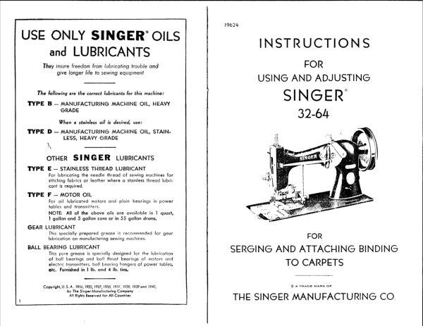
USE ONLY SINGER’ OILS
and LUBRICANTS

They insure freedom from lubricating trouble and
give longer life to sewing equipment

The following are the correct lubricants for this machine:

TYPE B — MANUFACTURING MACHINE OIL, HEAVY
GRADE

When a stainless oil is desired, use:

TYPE D — MANUFACTURING MACHINE OIL, STAIN-
LESS, HEAVY GRADE
\,

OTHER SINGER LusricaANTs

TYPE E — STAINLESS THREAD LUBRICANT
For lubricating the needle thread of sewing machines for
stitching fabrics or leather where a stainless thread lubri-
cant is required.

TYPE F — MOTOR OIL
For oil lubricated motors ond plain bearings in power
tobles ond transmitters
NOTE: All of the above oils are available in 1 quart,
1 gallon end 5 gallon cans or in 55 gallon drums.

GEAR LUBRICANT

This specially prepared grease is recommended for gear
lubrication on manufacturing sewing machines.

BALL BEARING LUBRICANT
This pure grease is specially designed for the lubrication
of ball bearings and ball thrust bearings of motors and

electric transmitters, ball bearing hangers of power tables,
etc. Furnished in 1 Ib. and 4 Ib. tins.

Copyright, U.S.A. 1916, 1922, 1927, 1995, 1937, 1938, 1939 ond 1940,
by The Singar Manufacturing Company
‘All Rights Reserved for All Countries

19624

INSTRUCTIONS

FOR
USING AND ADJUSTING

SINGER’
32-64

FOR
SERGING AND ATTACHING BINDING
TO CARPETS

AEA TRADE MARK OF

THE SINGER MANUFACTURING CO
View original page 1
Page 2 · Read text
2

DESCRIPTION

SINOFR’ 2-4 Zigzag Lock Stitch Machine has a vibrating
needle and an oscillating shuttle, and 1s especially designed
for serging and attaching binding to carpets in one operation.

This machine 1s equipped with upper wheel feed; also with
special guides to provide for various depths of bight and to con-
form to various thicknesses of carpets. Tape up to 2 inches in
width can be handled,

Speed

‘The maximum speed recommended for Machine 32-64 19 1200
stitches per minute, depending upon the nature of the material
being sewn,

‘The machine should be operated at less than the maximum speed
unt41 the parts which are in movable contact have become glazed
by their action upon each other.

When the machine is in operation, the balance wheel should
always tum over toward the operator,

TO ALL WHOM IT MAY CONCERN:

The improper placing or renewal of the Trade Mark "SINGER" or
ony other of the Trade Marks of The Singer Manufacturing Company
(all of which are duly Registered Trade Marks) on any machine that
hos been repaired, rebuilt, reconditioned, or altered in any way whatsoever
outside a SINGER factory or an authorized SINGER agency is forbidden.

SINGER Needles should be used
in SINGER Machines.
These Needles and their Containers
are marked with the
Company's Trade Mark "“SIMANCO.*" |

Needles in Containers marked
“FOR SINGER MACHINES"
are NOT SINGER made needles, 2

3
To Oil the Machine
Use "TYPE B* or *TYPE D* OIL, sold only by Singer sewing

Machine Company. For description of these oils, see inside
front cover.

To insure easy running and prevent unnecessary wear of the
parts which are in movable contact, the machine requires of ling,
When in continuous use, the machine should be oiled twice daily.

Fig, 2, otling Points at the Face (Left and End) of Machine
Remove the three screws (K,Fig.3) and remove the face plate.
Apply a drop or two of ofl at (A,Fig.2) for the upper end of

the needle bar frame; at (B) where the presser bar 1s in contact
with the upper bushing; at (C) where the needle bar passes
through the upper bushing; to the o11 hole at (D) at the upper
end of the needle bar connecting link; at (B) where the lower end
of the noedle bar link 1s attached to the needle bar connecting
stud; at (F) where the needle bar passes through the lower bush-
ing; at (G) where the lower end of the presser bar passes through
the machine casting; to the of1 hole (it) at the lower end of the
needle bar frame, and at (J) where the fork of the needle bar
contiecting stud Slides on the presser bar.
View original page 2
Related documents and language editions
SingerPDF
Singer 11w6 & 11w8
User manual
13 pages · EnglishRead →
SingerPDF
Singer 13K
User manual
12 pages · EnglishRead →
SingerPDF
Singer 144w204, 144w304
User manual
28 pages · EnglishRead →
SingerPDF
Singer 145w103, 145w203, 145w303
User manual
24 pages · EnglishRead →
SingerPDF
Singer 16-188
User manual
45 pages · EnglishRead →
SingerPDF
Singer 17-22 & 17-23
User manual
12 pages · EnglishRead →
SingerPDF
Singer 29-4
User manual
17 pages · EnglishRead →
SingerPDF
Singer 29-4 (black and white scan)
User manual
7 pages · EnglishRead →
SingerPDF
Singer 29-4 parts list
Parts list
18 pages · EnglishRead →
SingerPDF
Singer 29K parts list
Parts list
34 pages · EnglishRead →
SingerPDF
Singer 29k58 & 29k62
User manual
33 pages · EnglishRead →
SingerPDF
Singer 31-19 & 31-47
User manual
20 pages · EnglishRead →
From the ISMACS International. Original publisher and archive notices are retained.
Check the model and edition against your equipment.
PDF verified 2026-10-11.