Industrial sewing machines
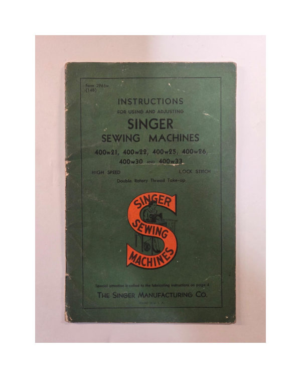
Singer 400W21, 400W22, 400W25, 400W26, 400W30, 400W33 — User manual
User manual for Singer 400W21, 400W22, 400W25, 400W26, 400W30, 400W33. 44 pages in English. Read the original PDF, download or print a copy without registration.
44 pagesEnglish36.5 MB PDF
Loading your manual…Open PDF directly
Document details
- Brand
- Singer
- Model / document
- Singer 400W21, 400W22, 400W25, 400W26, 400W30, 400W33
- Document type
- User manual
- Language
- English
- Pages
- 44
- File size
- 36.5 MB
- Category
- Industrial sewing machines
- Document date
- Not specified in catalog
Search available document text
Find a term, then jump to its page in the original PDF. Image-only pages may not be searchable; check the PDF for exact wording and diagrams.
Page 1 · Read text
Form 2966w
(148)

      INSTRUCTIONS

         FOR USING AND ADJUSTING
      SINGER
  SEWING MACHINES

  400w21, 400w22, 400w25, 400w26,
         400w30 AND. 400w33.

  HIGH SPEED                  LOCK STITCH

            Double Rotary Thread Take-up


       SINGER

      SEWING


       MACHINES


      Special attention is called to the lubricating instructions on page 4

   THE SINGER MANUFACTURING CO.
View original page 1Page 2 · Read text
USE ONLY "SINGER" OILS
    and LUBRICANTS

     They insure freedom from lubricating trouble and give
                 longer life to sewing equipment


          The following are the correct lubricants for the
                 241, 400w and 4/0w Machines:

 TYPE A - MANUFACTURING MACHINE OIL, LIGHT
           GRADE


                 When a stainless oil is desired, use:

  TYPE C - MANUFACTURING MACHINE OIL, STAIN-
             LESS, LIGHT GRADE


      OTHER "SINGER" LUBRICANTS

• TYPE E - STAINLESS THREAD LUBRICANT
          For lubricating the needle thread of sewing machines for
              stitching fabrics or leather where a stainless thread lubricant
                is required.
 TYPEF - MOTOR OIL
          For oil lubricated motors and plain bearings in power
            tables and transmitters.
        NOTE: All of the above oils are available in 1 quart,
            1 gallon and 5 gallon cans or in 55 gallon drums.

 BALL BEARING LUBRICANT
           This pure grease is specially designed for the lubrication
            of ball bearings and ball thrust bearings of motors and
             electric transmitters, ball bearing hangers of power tables,
             etc. Furnished in 1 lb. and 4 lb. tins.


  Copyright, U. S. A., 1914, 1915, 1922, 1926, 1935, 1940, 1941, 1944, 1946, 1947 and 1948,
                      by The Singer Manufacturing Company
                                All Rights Reserved for all Countries
View original page 2Page 3 · Read text
INSTRUCTIONS

       FOR USING AND ADJUSTING
    SINGER
 SEWING MACHINES

400w21, 400w22, 400w25, 400w26,

      400w30 AND 400w33


               SINGER


     SINGLE NEEDLE
                              LOCK STITCH


THE SINGER MANUFACTURING CO.
View original page 3Page 4 · Read text
TO ALL WHOM IT MAY CONCERN:


    The improper placing or renewal of the Trade-Mark "SINGER" or
 any other of the Trade-Marks of The Singer Manufacturing Company
 (all of which are duly Registered Trade-Marks) on any machine that
 has been repaired, rebuilt, reconditioned, or altered in any way whatsoever
 outside a Singer factory or an authorized Singer agency is forbidden.


       THE IMPORTANCE OF USING
    GENUINE "SINGER" PARTS AND NEEDLES
              IN "SINGER" MACHINES

   The successful operation of "SINGER" machines can only be assured
if genuine "SINGER" parts and needles are used. Supplies are avail-
able at all Singer Shops for the Manufacturing Trade, and mail orders
will receive prompt attention.


              Genuine "SINGER" Needles should be
                    used in "SINGER" Machines.
                These Needles and their Containers
                        are marked with the
              Company's Trade Mark "SIMANCO."


                  Needles in Containers marked
                "FOR SINGER MACHINES"

                are NOT "SINGER" made needles.
View original page 4Page 5 · Read text
DESCRIPTION


     Machine 400w21 is a high speed, single needle, lock stitch machine
  equipped with a double rotary thread take-up. It has a belt-driven, auto-
  matically lubricated rotary sewing hook on a horizontal axis. The drop
  feed is adjustable for stitches from 5½ to 30 per inch. The needle bar stroke
   is l& inches and the maximum presser bar lift is i inch. The machine is used
   for stitching light and medium weight fabrics.


      Machine 400w22 is the same as Machine 400w21 except that it has fe inch
  presser bar lift and is adapted for stitching medium heavy weight fabrics.


     Machine 400w25 is designed for shoulder joining on shirts, otherwise
    it is similar to Machine 400w21.


     Machine 400w26 is the same as Machine 400w21 except that it is espe-
  cially designed for ruffling shirt yokes, being fitted with an intermittent ruffler
  which is thrown into or out of action at the will of the operator by means of
 a treadle.


     Machine 400w30 is the same as Machine 400w21 except that it has a
  differential feed which especially adapts it for stitching knit goods and other
  elastic materials, also for shirring or gathering.

    The differential feed consists of two feed dogs arranged in tandem and
 separately adjusted by independent stitch regulators. Thus, the feeding
 movement of the feed dogs can be varied in relation to each other to pro-
 duce a wide variety of seam conditions. With this type of feed, it is possible
 to stitch knitted skirts and other articles made of more or less elastic mate-
 rials, and have the work lie perfectly flat when stitched. It also enables the
 operator to produce uniform gathering or shirring effects on house dresses,
 bed spreads, etc.


    Machine 400w33 is the same as Machine 400w21 except that it is regu-
 larly equipped with a 3z" hemmer and has a mechanical hem deflector which
 is operated from the bed shaft to produce a scallop at every sixth stitch,
forming a neat and attractive shell edge stitching effect on ladies' lingerie,

 children's underwear, dresses, etc.
View original page 5Page 6 · Read text
SPEED
                                                                                                     oil
    The speed recommended for these machines is 5000 R.P.M., except the
 400w26 which has a speed of 4500 R.P.M. It is advisable to run a new machine
 slower than the maximum speed for the first few minutes to allow time for the
 oil to reach the moving parts. The balance wheel turns over from the
 operator.


                       SETTING UP

    The drip pan should be attached with its right end even with the right
 end of the cut-out and low enough in the cut-out to avoid interference
     FRONT EDGE OF TABLE         with the knee lifter rod A, Fig. 2.
         = 34         Fig. 2 shows the correct location of
                                       the knee lifter. The knee lifter bracket
                                     should be assembled so that the lifter
                                 rod A does not strike the drip pan.
                             The screw slots in the bracket pro-
                                      vide the necessary adjustment. The
                                    stop stud B, Fig. 2 should be set to
                                  stop the action of the knee lifter as
                             soon as the presser foot is raised                           th
                             enough to trip the hand lifter.

                             CAUTION: Do not start a ma-
                                    chine, not even to test the speed,
                                                                                                             oi
                                              until it has been thoroughly oiled as
                                         instructed on page 4.
 Fig. 2. Position of Knee Lifter Under Table

    NOTE: For setting up Machine 400w26, see page 34.

                   OILING THE MACHINE


    Use TYPE A or TYPE C OIL, sold only by Singer Sewing Machine Com-
 pany for 241-, 400w and 410w Machines. For description of oils, see inside of
 front cover.

   A reservoir in the bed of the machine supplies oil to the sewing hook
race and to the bearings and eccentrics on the hook driving shaft (except
the rear ball bearing). The other lubrication points are reached by seven
oil holes, marked with red. See "X-Ray" view of machine on pages 20 and 21.
View original page 6Page 7 · Read text
BEFORE STARTING THE MACHINE, fill the oil reservoir (through the
                                 oil gauge hole to the top mark on the oil gauge E, Fig. 3.
he
ine

the
the

                               SINGER


ight
nce
 2.
1 of
cket
ifter
dan.
bro-

The
+ to                                           Fig. 3. Showing the Eight Oiling Points on the Machine
as                         While it may not be necessary to add oil to the reservoir every day,
sed                   the oil level must be checked DAILY and filled to the high mark. Never
                       allow the oil level to drop below the lower mark on the oil gauge.
                    AT THE BEGINNING OF EACH WORKING DAY, turn thebalance10-
                     wheel until the needle is ALL THE WAY UP, and place A FEW DROPS of
ed,                            oil in each of the seven oil holes indicated by the arrows in Fig. 3.
as                 On Machine 400w26, in addition to the above oiling points, oil must be
                       applied to the oil cup B, and oil hole R, Fig. 39, twice a day.

                                              NEEDLES
                          Needles for these machines are as follows:

                           Machine       Class and Variety                       Sizes

                        400w21
                                                                   7, 8, 9, 10, 11, 12, 13, 14, 16, 17,
- m-                    400w30         88X1                                                               18, 19 and 21
 of                  400w33
                                                                        8, 9, 10, 11, 12, 13, 14, 16, 18, 19,
                       400w22        135X5                                                   and 21

                     400w25                              7, 8, 9, 10, 11, 12, 14, 16, 18, 20                                    135X7
n                      400w26                       and 21
                       The above needles regularly have nickel finish but can be supplied with
                     chromium finish if ordered.
View original page 7Page 8 · Read text
The size of the needle to be used should be determined by the size of
 the thread, which must pass freely through the eye of the needle.Rough
 or uneven thread, or thread which passes with difficulty through the eye of
the needle, will interfere with the successful use of the machine.
    Orders for needles must specify the Quantity required, the Size number,
also the Class and Variety numbers separated by an x.

     The following is an example of an intelligible order:
                       "50 No. 16, 88xl Needles."

     The best stitching results will be obtained by using the needles furnished
 by Singer Sewing Machine Company.

                       THREAD
     Left twist thread should be used in the needle. Either right or left twist
thread can be used in the bobbin.


                                              E1739


                            Fig. 4. How to Determine the Twist
    Hold the thread as shown above. Turn the thread over toward you
between the thumb and forefinger of the right hand; if left twist, the strands
will wind tighter; if right twist, the strands will unwind.

               TO REMOVE THE BOBBIN
   Turn the balance wheel over from you until the needle moves up to
its highest position. Draw back the slide in the bed of the machine.Reach
                                  under the table and
                                    openthe bobbin case
                                                latch D, Fig. 5 and, by
                                  means of this laich, re-
                                move the bobbin case
                                            from the sewing hook.
                                     While the latch re-
                                         mains open, the bobbin
                                                      will be retained in the
                                    bobbin case.  Release
                                              the latch, turn the open
                                      end of the bobbin case
                D      downward and the bob-
                                             bin will drop out.

               Fig. 5. Removing the Bobbin
View original page 8Page 9 · Read text
TO WIND THE BOBBIN

                                                             (See Fig. 6)

                      Fasten the bobbin winder to the table with its driving pulley in front
                         of the machine belt, so that the pulley will drop away from the belt when
                           sufficient thread has been wound upon the bobbin.


st


                         B                                  E18152


ds                                                          Fig. 6. Winding the Bobbin

                       Place the bobbin on the bobbin winder spindle and push it on as far
                   as it will go.

                     Pass the thread down through the thread guide I in the tension bracket,
                     around the back of, and between, the tension discs 2. Then wind the end of
                      the thread around the bobbin a few times in the direction shown in Fig. 6,
                   push the bobbin winder pulley over against the machine belt and start the
                     machine.

                  When sufficient thread has been wound upon the bobbin, the bobbin
                     winder will stop automatically.

                                          If the thread does not wind evenly on the bobbin, loosen the screw A
                          in the tension bracket and move the bracket to the right or left as may be
                        required, then tighten the screw.

                     The amount of thread wound on the bobbin is regulated by the screw B.
                   To wind more thread on the bobbin, turn the screw B inwardly. To wind
                       less thread on the bobbin, turn this screw outwardly.

                       Bobbins can be wound while the machine is stitching.

                  When winding a bobbin with fine thread, a light tension should be used.
View original page 9Page 10 · Read text
TO THREAD THE BOBBIN CASE


FF
                                Hold the bobbin between the thumb
                         and forefinger of the right hand, as

                          shown in Fig. 7, the thread drawing on
                                the top from the left toward the right.


   EITSIS


                Fig. 7


  With the left hand hold the bobbin case
as shown in Fig. 7, the slot in the edge being
near the top, and place the bobbin into it.


                                                                     Fig. 8


                       Then pull the thread into the slot in the
                        edge of the bobbin case as shown in Fig. 8;
                         draw the thread under the tension spring and
    C4000                      into the delivery eye at the end of the ten-
                             sion spring. See Fig. 9.


              Fig. 9
View original page 10Page 11 · Read text
TO REPLACE THE BOBBIN CASE

    After threading, take the bobbin case by the latch and place the bob-
bin case on the center stud C, Fig. 5 of the bobbin case holder; release


                         Fig. 10. Bobbin Case Threaded and Replaced


the latch and press the bobbin case back until the latch catches the groove
near the end of the stud. See Fig. 10. Allow about two inches of thread
to hang free, and replace the slide in the bed of the machine.


                  TO SET THE NEEDLE

   Turn the balance wheel over from you until the needle bar moves up
to its highest point; loosen the screw at the lower end of the needle bar
and put the needle up into the bar or clamp as far as it will go, with the
long groove of the needle toward the left and the eye of the needle
directly in line with the arm of the machine, then tighten the screw.
View original page 11Page 12 · Read text
10


                     UPPER THREADING
                                  (See Fig. 11)                                             th
                                                                                  be

    As soon as an operator has become accustomed to threading the ma-
  chine, the thread can be passed from the thread retainer at the top, down
  to the needle with a single continuous motion.
     Turn the balance wheel over from you until the two pins P in the rotary                   fr
 take-up are directly toward the front, as
 shown in Fig. 11 inset.

    Pass the thread from the unwinder through
 the top hole I in the pin on top of the ma-
 chine, then around and through the lower hole
   2 in the pin, thence through the three holes
 3, 4 and 5 in the thread
 retainer. Hold the thread
 with the right hand near
 the thread retainer while      2
 passing the thread, with
 the left hand, downward          5 4 3
 into the inner slot 6
 (guiding it into the hole

 7) and on down in front of

 the tension discs 8, around
 between the tension discs ER
 into the take-up spring 9                                                                     th
                                                                                                th and under the thread pull-
 off 10 then over through the      7                                                       bc slot 11, allowing the thread       6                             11            12to fall in placeover the
 take-up discs. Now release
 the thread with the right
hand, and pass it down                 10                                                        -13
through the guides (12, 13
and 14*), then from left to                                -14
right through the eye of the
                                                   -15needle 15. Leave about
three inches of thread with
which to commence sewing.


                                                  Fig. 11. Threading the Needle
View original page 12Page 13 · Read text
*NOTE: The thread guide 14 should be turned on the needle bar bushing so that the
thread leads in a straight line from the guide 13 to the needle eye. The thread retainer 5 should
be turned so that the thread leads through the center of hole 7.


               TO PREPARE FOR SEWING

   With the left hand hold the end of the needle thread, leaving it slack
from the hand to the needle, turn the balance wheel over from you until


                                              6/8/22


                           Fig. 12. Drawing Up the Bobbin Thread


the needle moves down and up again to its highest point, thus catching
the bobbin thread; draw up the needle thread and the bobbin thread will
come up with it through the hole in the throat plate. See Fig. 12. Lay
both threads back under the presser foot.


                TO COMMENCE SEWING

   Place the material beneath the presser foot, lower the presser and
commence to sew, turning the balance wheel over from you.


                TO REMOVE THE WORK

    Stop the machine when the needle bar has just started to descend or
with the two pins P, Fig. 11 in the rotary take-up directly toward the front.
 In this position the upper thread will be free of the sewing hook and the
take-up will not unthread the needle when the machine is started. Raise the
presser foot, draw the work back and cut the threads close to the work.
View original page 13Page 15 · Read text
TENSIONS

    For ordinary stitching, the needle and bobbin threads should be locked
in the center of the thickness of the material, thus:


                                    Fig. 16. Perfect Stitch

       If the tension on the needle thread is too tight, or if that on the bob-
 bin thread is too loose, the needle thread will lie straight along the upper
surface of the material, thus:

              BE

                             Fig. 17. Tight Needle Thread Tension


      If the tension on the bobbin thread is too tight,or if that on the needle
thread is too loose, the bobbin thread will lie straight along the under side
of the material, thus:


                            Fig. 18. Loose Needle Thread Tension


               TO REGULATE THE TENSIONS

  THE TENSION ON THE NEEDLE THREAD SHOULD BE REGULATED
ONLY WHEN THE PRESSER FOOT IS DOWN. Having lowered the presser
foot, turn the small thumb nut at the front of the tension discs over to the
right to increase the tension. To decrease the tension, turn this thumb nut
over to the left.
   The tension on the bobbin thread is regulated by the large screw
FF, Fig. 7 in the tension spring on the outside of the bobbin case.
increase the tension, turn this screw over to the right. To decrease the
tension, turn this screw over to the left.
  When the tension on the bobbin thread has been once properly
adjusted, it is seldom necessary to change it, as a correct stitch can usually
be obtained by varying the tension on the needle thread.
View original page 15Page 16 · Read text
14


         TO REGULATE THE PRESSURE ON THE MATERIAL

     The pressure of the presser foot on the material is regulated by the
  screw F, Fig. 19 in the top of the arm. Turn this screw to the right to increase
  the pressure or to the left to decrease the pressure. The pressure should
  be set only sufficiently strong to satisfactorily feed the work.


              SINGER


                            Fig. 19. Stitch Regulator and Indicator


           TO REGULATE THE LENGTH OF STITCH
                        (Except on Machine 400w30)

    To change the length of stitch, press down the stud H, Fig. 19 in the
bed of the machine and at the same time turn the balance wheel slowly
 until the stud enters a notch in the adjustable feed eccentric cam.Still
holding the stud, turn the balance wheel a part of a revolution until the
number indicating approximately the number of stitches per inch desired
appears in the hole G over the large take-up disc, then release the stud.
DO NOT TOUCH THE STUD H WHILE THE MACHINE IS RUNNING.
View original page 16Page 17 · Read text
15


            TO REGULATE THE LENGTH OF STITCH
                        (On Machine 400w30)
     To change the length of stitch, press down the two studs L and R, Fig. 20
 in the bed of the machine and at the same time turn the balance wheel
 slowly until each stud enters a notch in its adjustable feed eccentric cam.
 Still holding the studs, turn the balance wheel a part of a revolution until the
 desired number appears in the hole G over the large take-up disc, then
 release the studs. Both feed dogs are now set to produce the same length
 of stitch.

               SINGER


                         R
                      L


                                                    Fig. 20

   When the machine is to be used for shirring or gathering or for stitching
 knit goods or other elastic materials, the feed dogs should be separately
adjusted to vary the feeding movement of each according to the require-
ments of the work. The front feed dog For the one nearest to the operator
 is adjusted by means of the left stud L. The rear feed dog B or the one
 farthest from the operator is adjusted by means of the right hand stud R.
NEVER TOUCH THE STUDS L and R WHILE THE MACHINE IS RUNNING.
To Shirr or Gather the Material
    Press the left stud. L, Fig. 20 and set the front feed dog, or the one
 nearest you, to make a longer stitch than that for which the rear feed dog
 is set.
To Stretch the Material
    Set the rear feed dog for a longer stitch than that for which the front
feed dog is set.
View original page 17Page 18 · Read text
16


                 HINTS FOR PERFECT OPERATION


    Follow instructions and oil machine regularly.

    The balance wheel must always turn away from the operator.

    Do not run machine with bobbin case only partly inserted.

   Do not run the machine with the presser foot resting on the feed
 without cloth under the presser foot.

    Do not run the machine when both bobbin case and needle are threaded
 unless there is material under the presser.

   Do not try to help the machine by pulling the fabric lest you bend the
 needle. The machine feeds the work without assistance.

    The slide over the bobbin case should be kept closed when the machine
 is in operation.

   Do not press on the knee lifter lever while the machine is in operation,
 as this might prevent the work from feeding properly.

    Occasionally remove the accumulation of lint from around the hook
and from between the feed rows beneath the throat plate.

   NEVER TOUCH THE STITCH REGULATOR STUD WHEN THE MACHINE
IS RUNNING.
View original page 18Page 20 · Read text
18

                    TIMING THE MACHINE

    The parts are in their proper timing on the various shafts when the
  locating screws are in the shaft splines provided for them. These locating
 screws are the first screws appearing when the shafts are revolved in
 their normal direction of rotation.


           XX  E2     GG

                                  G

                     000


                              C2

                 V


                      D2


               Fig. 21. Showing Timing Marks on Take-Up Discs and Face Plate


    The arm shaft, auxiliary take-up shaft and hook driving shaft with their
 component parts are in time with each other when the arrow G, Fig 21
on the large take-up disc is in line with mark GG, Fig. 21 on the face plate,
the arrow X, Fig. 21 on the small take-up disc is in line with mark XX on the
face plate, and the arrow on the collar V1, Fig. 30 is in line with the
timing mark W1, Fig. 30 on the feed lifting connection. The needle bar
and hook are timed as described on page 23.
View original page 20Page 21 · Read text
TO ADJUST THE THREAD TAKE-UP SPRING

                   AND PULL-OFF

    The horizontal portion of the thread pull-off, L, Fig. 22, should be set
 about 32 inch below the bottom of the set screw, K, Fig. 22, when the
 presser foot is raised by the presser bar lifter. The pull-off can be raised

 or lowered after loosening the set screw J.


            JJ


           L


                             Fig. 22. Take-Up Spring Adjustments


   The take-up spring should have just enough movement so that it will
be through acting and will rest against the upper end of spring regulator
M when the eye of the needle is about it inch above the goods on the
downward stroke of the needle. After loosening the set screw K, the
tension will turn with the stud N and the spring regulator may be turned
to the required position.

   The tension on the thread take-up spring O is regulated by turning
the tension stud N to the right to increase the tension, or to the left to
decrease the tension. The tension on the thread take-up spring should be
just sufficient to take up the slack of the needle thread until the eye of
the needle reaches the goods in its descent.

   The above instructions apply to average operation. Adjustments in
both setting and tension may have to be made to suit special conditions.
View original page 21Page 24 · Read text
22


                   PRESSER BAR ADJUSTMENTS

     The presser bar bushing T, Fig. 24 should be set so that its top is about
           i inch below the top of the lifting bracketS when the bracket is all the
  way down.
     The presser bar position guide U should be set about i inch above                 B1
  the top of the lifting bracket S when the presser foot is down on the throat
                                                                                             the
  plate. The spring between the guide U and bracket S cushions the action
  of the lifting bracket.                                                                        the
     To align the presser foot with the needle, have the presser down on               ba
  the throat plate, hold the presser bar position guide JJ, Fig. 22 from slip-
  ping either up or down, loosen screw U2, Fig. 24, move the presser foot
  to the desired position and re-tighten the screw.
     With the feed dog and presser foot down, there should be a slight.
  free motion in the hand lifter lever so that the presser foot will rest on the
  work during operation of the machine.


                                         .P2


                             U2

                            U
                       V


                                                         C18194

                                  Fig. 24. Face Plate Removed

          ADJUSTMENT OF THE TENSION RELEASER
    The tension releaser R, Fig. 24 automatically releases the spring pres-                 Re
sure on the tension discs when the presser bar is raised. The releaser may
be moved up or down to release the tension earlier or later, by loosening                       in
the screw Q.
   When stitching on heavy material, the releaser should be set lower                 up
than when on light work to prevent stitching with a released tension while
sewing heavy material.
View original page 24Related documents and language editions
SingerPDF
Singer 11w6 & 11w8
User manual
13 pages · EnglishRead →
SingerPDF
Singer 13K
User manual
12 pages · EnglishRead →
SingerPDF
Singer 144w204, 144w304
User manual
28 pages · EnglishRead →
SingerPDF
Singer 145w103, 145w203, 145w303
User manual
24 pages · EnglishRead →

SingerPDF
Singer 16-188
User manual
45 pages · EnglishRead →
SingerPDF
Singer 17-22 & 17-23
User manual
12 pages · EnglishRead →
SingerPDF
Singer 29-4
User manual
17 pages · EnglishRead →
SingerPDF
Singer 29-4 (black and white scan)
User manual
7 pages · EnglishRead →

SingerPDF
Singer 29-4 parts list
Parts list
18 pages · EnglishRead →

SingerPDF
Singer 29K parts list
Parts list
34 pages · EnglishRead →
SingerPDF
Singer 29k58 & 29k62
User manual
33 pages · EnglishRead →
SingerPDF
Singer 31-19 & 31-47
User manual
20 pages · EnglishRead →
From the ISMACS International. Original publisher and archive notices are retained.
Check the model and edition against your equipment.
PDF verified 2026-10-11.