Industrial sewing machines
Singer 61w91, 61w92 — User manual
User manual for Singer 61w91, 61w92. 27 pages in English. Read the original PDF, download or print a copy without registration.
27 pagesEnglish11.4 MB PDF
Loading your manual…Open PDF directly
Document details
- Brand
- Singer
- Model / document
- Singer 61w91, 61w92
- Document type
- User manual
- Language
- English
- Pages
- 27
- File size
- 11.4 MB
- Category
- Industrial sewing machines
- Document date
- Not specified in catalog
Search available document text
Find a term, then jump to its page in the original PDF. Image-only pages may not be searchable; check the PDF for exact wording and diagrams.
Page 2 · Read text
USE ONLY SINGER OILS
    and LUBRICANTS

    They insure freedom from lubricating trouble and give
              longer life  to sewing  equipment


SINGER OIL FOR HIGH SPEED SEWING MACHINES
                               (Cloth  and  Leather)
          For  all manufacturing sewing  machines  except where a
            stainless oil  is desired.
SINGER STAINLESS OIL FOR  HIGHSPEED
SEWING MACHINES
          For  all  manufacturing sewing machines where a stainless
                   oil is desired.
SINGER MOTOR  OIL
          For oil-lubricated   motorS, power  tables,  transmitters  and
          machinery in general.
SINGER STAINLESS THREAD LUBRICANT
          For lubricating  the needle thread of sewing machines for
            stitching  fabrics or leather where a stainless thread lubri
          cant is  required.
       OTE: All of the cbove oils are availablein  1 quart, 2 qUort,
                   l gallon and 5gallon cans or in 55 gallon drums, and can also
          besupplied in  customer's  containers.

SINGER GEAR LUBRICANT
            This  specially  prepared  grease  is recommended  for gear
             lubrication on manufacturing sewing machines.
SINGER  BALL BEARING LUBRICANT
               This pure grease   is specially  designed  for the  lubrication
          of ball  bearings and   ball thrust  bearings of motors and
             electric transmitters,  ballbearing hangers of power tables,  etc.
          NOTE: The above greases are furnished  in     lb. tubes and                     4
          1b. and 4 Ib. tins.


                                    Copyrlght,U.           1915, 1922 and 1926,
                          by The Singer  Manufacturing   Company
                                                 All Rights Reserved   for    Countries
View original page 2Page 4 · Read text
To allwhom  it may concern:

   The placing or renewal  of the name "Singer'" (Reg. U.S.
 Pat.   Off.) or any of the trade marks of The Singer  Manu
 facturing Company on any machine that has been repaired,
 rebuilt, reconditioned,  or altered in any way whatsoever
 outside a Singer  factory  or an authorized  Singer  agency
 is forbidden.


          THE IMPORTANCE OF USING
     GENUINE SINGER PARTS AND NEEDLES
               IN SINGER MACHINES

   The successful operation of Singer machines can only be
assured  if genuine Singer  parts and needles are used.  Sup
plies are available at all Singer Shops for the Manufacturing
Trade and  mailorders  willreceive prompt attention.


             Genuine Singer Needles should  be used
                               in Singer Machines.
               These Needles and their Containers
                        are marked  with the
             Company's Trade Mark  SIMANCO."     1

                   Needles in Containers  marked
                        "For Singer Machines"
                    are not Singer made needles.    2
View original page 4Page 5 · Read text
MACHINES OF CLASSES
        61w and 62w

                DESCRIPTION

   Machines  of  above  Classes  contain  the  horizontal,  belt
driven,  rotating  sewing  hook  with  stationary  bobbin  case
mechanism  for making  the lock stitch at high speed in fabrics
and light leather  work,and are distinguished for absolute cleanli
ness  of operation, a feature  especially desirable in stitching
white goods.
   The link thread take-up is a   most.efficient  device  for  its
purpose.  It consists of a light and strong lever and link, working
silently without the use of cam or spring.  It is capable of the
highest speed without vibration  of the machine, and with least
friction and wear  of parts.  The bearings and wearing  parts
are of such generous size and construction  that the machines
do their work  under severe conditions for a long time without
showing appreciable  wear.
   Machine 62w 1 is designed forsewing tubular articles; other
wise similar  to  Machine 61 w 52.
View original page 5Page 7 · Read text
Machines, and Needles  Adapted for Them

  61 w 52                          61 w 66
   61 w 62                                   61w 156   USE NEEDLE 135X 5
  61w 63                          61 w 157
   61 w 72
                                                                                           X 1     61 w 74   USE NEEDLE  135
   61 w 76
  61 w   7                            61 w 80   USE NEEDLE 135 X 4
  61 w 84
  61 w 154

   The needle  which  is best adapted  for thework  that the
machine is fitted to dois set in the machine at the factory.
   The size No. of the needle is marked  upon  its shank.
   The  successful use of a sewing machine  depends  largely
upon  the quality and size of the needle  in use.  When  needles
are to be ordered the Class and Variety of the machine, as shown
by its number plate, and the line of work  to be accomplished
must be considered, therefore the order should callfor the style
and size of the needle required,asshown by the Needle Table and
the list of Relative  Sizes of Needles and Thread.  The size to
be used should be determined by the size of the thread, which
must pass freely through the eye.  If rough or uneven thread is
used, or if it passes  with difficulty  through the eye of the needle
the successful use of the machine will be interfered with.
    Orders for needles must specify the quantity required, the
size, also the class and variety numbers  separated by x.  In
theclass and variety of needle of which various styles of points
are made the order should also specify the style of point required.
    The following are details of an intelligible  order:
       "100 No. 14  135 x 4 Reverse Triangular Point Needles."
        100No. 12  135x5 Needles."
    The best results will be obtained  in using the needles fur
nished by the Singer Sewing  Machine  Company.
View original page 7Page 8 · Read text
RELATIVE SIZES OF NEEDLES AND THREAD
   NEEDLES  FOR LEATHER WORK          FOR CLOTH WORK
       Size                    Cotton           Silk                  Cotton                 Silk
  Naumbers f    Thread      Thread            Thread            Thread
     Needles
                                           100 to 150    O00 to00      10         70    O0 and O
                                        90    100       00       11          60
                                        80    90      12        50
       13         40                      70    80         A
     14         36                             70         A
     15         30                      50    60       B
                                              50        C       16         30        E            40 (
     18        24                       30    40        C
     20        20                         24     30        D
                                            16     24          E    22            16  |

      Twist, Linen and Cotton Thread and Needles

    To make a smooth,even stitch with your sewing  machine,
use good,  firmly twisted and smoothly  finished  thread, that
                                                   other needlespasses freely through  the eye of the needle.  No
will give as good results and satisfaction as those recommended
above.
    In using  slack twist or uneven silk, should  it be frayed or
roughened, the needle is too fine or too sharp, or has a hooked
point, made by striking the throat plate.  A hook may be easily
honed  off the needle.
    For ordinary work use the samesize of thread on the bobbin
as in the needle.
    Ready wound bobbins  for Singer Sewing Machines are sold
by thread manufacturers.
View original page 8Page 9 · Read text
7


                       L
                                           IL  L                  39


                                                                               10


                                   QUL


                                                       51A


                                        Fig. 2
               To Oil the Machine
   Good  oil is the life of a machine, and should be regularly
used on any surface  of metal which  comes  in movable  contact
with another surface.
   The large hole on top of the arm near the take-up lever is
for serew driver use.
    There are five oil holes outside of the arm and bed as follows:
     1st. Back of the large hole, to oil the conduit to the take-up
lever hinge stud (see Fig. 3).
    2nd.  The  oil packing  wick thumb serew, to  oil the arm
shaft bushing (front) and conduits (see Fig. 3).
    3rd. Near the balance wheel, to oil the arm shaft bushing
(back).
    4th. Near the bed on the inside of the  arm, to oil the hook
shaft bushing (back).
     5th.  In the center of the bed plate, to oilthe hook  shaft
bushing (tront).
   Move the arm cap aside, to oil the feed connections.
   Move the face plate  aside,to oil the needle bar connecting
link stud, the needle and presser bars,and the slide behind the
link (see Fig. 3).
View original page 9Page 10 · Read text
8

    Tip the machine   back, to  oil each end of the rock shafts.
the feed  bar, slide  block, and the connection hinge screws (see
Fig.   2).
     Oil the bearings at both ends of the treadle, pitman  and
shaft, and all other movable parts of the transmitter,  ete.


                                                         OIL
                                       OIL


                     OlL
                      PAD


                                    Fig. 3

                            Oil Conduits
     Fig. 3shows that the shaft and studs are hollow and illed
 with oil wicking, as are also the conduits for conducting  the oil
 from the shaft through  the needle bar crank to the needle bar
 driving and the take-up  driving  studs.  The  centrifugal  force
 works  the  oil from  the shaft to the bearing and through  the
 conduits and studs.  There is a conduit from the top of the arm
 to the stationary take-up stud.
View original page 10Page 11 · Read text
Oilthe bobbin case bearing  in the hook race each time a
bobbin   is replaced.

  When a machine  has been  neglected  or becomes  gummed,
it should be soaked well with benzine and run for a short time,
keeping  allparts flooded with  oil, until it runs freely, then wipe
thoroughly  to remove all  old  oil and dirt and  oil  as before
directed.
   Never run the machine  with the presser foot down except
when sewing, as it will seratch the presser foot and dull the teeth
of the feed dog.


                To Set the Needle

    Push  the needle up in the needle bar as far as it  will  go,
with the long groove to the right, or toward  the column  of the
arm,and secure it firmly with the set screw.
    It may be necessary to turn the needle slightly to the right
or left for some threads, if stitches are missed.
    Operators  are  liable to  use  needles  which  are too fine.
Better results usually  follow  theuse of a larger size.
    For ordinary work use the same size of thread on the bobbin
as in the needle.
View original page 11Page 12 · Read text
10


       FOR MACHINES WITHOUT OPENERS

            To Thread  the Bobbin Case

   Place the bobbin  in the bobbin  case, with the thread leading
from the top toward you; hold the thread with the right hand


                                                          LATCH


                                FiG. 4


(see Fig. 4), guide it into the notch  (close the latch) and draw
until the thread  is under the spring on the bobbin  case, or
drawing the thread up through  theneedle hole in the throat plate
 willdraw the thread under thespring asyou start to sew.
View original page 12Page 13 · Read text
11

        FOR MACHINES WITH OPENERS
             To Remove the Bobbin
   Draw out the slide in thebed of the machine.  Reach down
with the thumb and forefinger of the left hand, open the bobbin
case latch with the forefinger and lift out the bobbin  case cap.
While the latch remains  pen, the bobbin is retained in the bobbin
case cap.  Release the latch, turn the open end of the bobbin case
cap downward and the bobbin  will drop out.
         To Thread the  Bobbin Case Cap
   Hold  the bobbin  between  the thumb and forefinger of the
righthand, the thread leading on the bottom  from the left toward
the right.
   With the left hand hold the bobbin case cap open side up and
place the bobbin  into  it.


                                       W 2416


                                FIG. 5
   Then pull the thread into the slot in the edge of the bobbin
case cap and under the tension spring and into the notch in the end
of the tension spring.
          To Replace the Bobbin Case Cap
    After threading, take the bobbin case cap by the latch, holding
it between  the thumb and forefinger of the left hand, place the
bobbin  case cap on the center stud  of the bobbin  case base.
Release the latch and press the bobbin  case cap back until the
latch catches the groove near the end of the stud.
View original page 13Page 14 · Read text
12

              To Thread the Needle
    Guide  the thread as shown in Fig. 6, and  as the thread  is
 Dassed around between  the tension discs draw  it up to the right
 untilit passes into the fork above the thread controller.


                               <STOP
                             SCREW


                                    E 5238


                                    FIG,   6


                        Roller  Presser

   For convenience  in threading, press down  on the roller and
swing it out to the left.
View original page 14Page 15 · Read text
13

               To Wind the Bobbin

                             (SEr FiG. 7)
    Fasten the bobbin winder tothe table with its driving pulley
 in front of the machine  belt,so that the pulley will drop away from
 thebelt when sufficientthread has been wound upon the bobbin.


                                                  A


                                                                         E4194

                        FIG. 7,  WINDING THE BOBBIN

    Place the  bobbin  on the bobbin  winder  spindle and push
it on as far as it will go.
   Pass  the thread down through  the thread guide  (1) in the
tension bracket, around  the back and between  the tension dises
(2). Then wind the end of  the thread around  the bobbin  a
few times, push the bobbin winder pulley over againstthemachine
belt and start the machine.
  When sufficient thread  has been wound upon the bobbin,
the bobbin winder will stop automatically.
    If the thread  does not wind  evenly on the bobbin, loosen
the screw (A)in the tension bracket and move the bracket to
the right or left asmay be required, then tighten the screw.
   The amount of thread wound on the bobbin  is regulated by
the screw  (B). To wind more thread on the bobbin, turn the
serew (B) inwardly.  To wind  less thread on the bobbin, turn
the serew outwardly.
   Bobbins  can be wound while the machine  is stitching.
View original page 15Page 16 · Read text
14

              To Commence Sewing
      With the left hand take hold of the needle thread, leaving
it slack between  the hand and the needle, turn the balance wheel
toward you  untilthe needle moves down and the take-up lever
rises to itshighest point, thus catching the bobbin thread; draw up
the needle thread and the bobbin thread with itthrough the needle
hole in thethroat plate and lay both threads back across the feed
dog: then place the material beneath the needle, lower the presser
foot upon it, turn the balance wheel toward  you and commence
to seW.
                 The Tensions
  To regulate the tensions, please observe the following:


                                    FiG. 8
  The upper  and under  threads should  lock in the center of
the material as shown in  Fig.8.


                                    FIG. 9
                                                                   its tension, or if    If the upper  thread  is held too tightly by
the under  thread is too loose, the thread will be straight along
the upper surface of the material as shown in Fig. 9.


                                                                                                  EII319
                                    FIG. 10

    If the under  tension  is too tight or the upper  too loose, the
thread  will  be straight along the under  side of the material,  as
shown in Fig. 10.
    To Regulate the Tension on the Under Thread
   The tension on the under thread  is regulated by the serew in
 the center of the tension spring on the outside of the bobbin case
 cap. To increase the tension turn this screw over to the right.
 To decrease the tension turn this screw over to the left. See that
 there is no lint or dirt under  the tension spring.
View original page 16Page 17 · Read text
15

    Correctly made  stitches, as shown in Fig. 8, can usually  be
obtained by regulating  the upper  tension only, turn the tension
thumb  nut  inwardly  to tighten and outwardly  to loosen the
tension  (see Fig. 6).
   Caution.    Do not try to adjust the upper  tension when the
presser foot is up,as the tension  is then released.


                   Feed Regulator

   The figures on the feed regulating  spindle head at the right
of the balance wheel, showing  through  the notch in the balance
wheel, indicate  the number of stitches to the inch which  the
machine  should make.  Turn the spindle head  until the figures
representing  the desired number of stitches to the inch appear
in the notch.


               To Turn a Corner

   Stop the machine  while the needle is rising, but before it is
out of the material,  raise the presser foot and turn the corner,
using the needle as a pivot.
   In sewing  where  special  elasticity is  required,  as on bias
seams or very elastic material,  hold the work back slightly, to
keep the cloth stretched while being sewed.

           The Pressure on the Material

   The  pressure  of the  presser  foot or of the  roller presser
should be only heavy enough  to assure an even length of stitch
and to prevent the work from rising with the needle; if too heavy
it will make the machinerun harder and be of no benefit.
   The pressure  is regulated by turning the thumb serew  (see
 Fig. 6) at the top of thearnm head  through  which  the presser
bar pasSses.

                        Roller Presser

   The roller should be set close enough  to the needle to steady
 it and prevent it from staggering, and far enough back to prevent
 the leather from stretching.
View original page 17Page 18 · Read text
16

                  To Remove the Work

     Raise the presser   lifter, turn  the machine  by the balance
wheel  until the take-up  lever is at its highest point and draw
 thework from  you.  Ifthe threads do not draw out easily,the
take-up lever is not in the right position, as directed.   If the
machine  is stopped as directed, the needle will not be unthreaded
in starting to sew, even  if only a short end is left through  the
needle.

     For convenience  in taking out the   work, the tension  of the
upper  thread  is released by raising the presser  foot with  the
lifter; but  is not released by thick goods or seams passing  under
the presser  foot. Do not try to adjust the upper  tension when
the presser lifter  is up as the tension is then released.
    Causes  of the machine not working  properly will usually
be found in the tension not being correctly adjusted, or its discs
may be clogged with lint or knots of thread, or the thread may
be too coarse or too fine for the needle, orthe needle and thread
too coarse or too fine for the throat  plate, or the needle bent or
 blunt. Seethat a straight needle is pushed up in the needle bar as
far as it   willgo; any particle of lint or dirt which prevents it from
going up can be removed through the eross hole in the needle bar.

                  Knee Lifter

    The knee  lifter  is used for raising the presser foot by knee
 pressure against the knee plate, leaving both hands free to manip
 ulate the work.   If the knee lifter does not raise the presser foot
 satisfactorily,adjust the rod in the rock lever which  connects
 with the rod in the arm of the machine  to lift the presser foot.
View original page 18Page 19 · Read text
INSTRUCTIONS
                     FOR
   ADJUSTERS AND MACHINISTS


                  Thread Controller

   The function  of the thread controller spring is to hold back
the slack of the upper thread until the eye of the needle reaches
the goods in its descent.
   For more controller action on the thread, loosen  the stop
serew  (see Fig. 6) at the right of the tension and set the stop
lower, and for less action set the stop higher.
   To strengthen  the  action  of the controller  spring on the
thread, loosen the tension stud screw (C, see Fig. 7) at the right
of the stop screw and turn the tension stud slightly to the  left
with a screw  driver, or to lighten  its  action turn to the right
and tighten the tension stud serew.

                        Feed
    To take up lost motion  of the feed connections,  adjust their
hinge and pinch serews.
    Toprevent the feed dog from striking at either end of the
slots in the throat plate, loosen the feed driving connection crank
pinch serew (51A, see Fig. 2) and move the feed dog forward
orbackward   until the longest stitch can be taken  without the
feed dog striking the throat plate and retighten the screw.

         To Raise or Lower the Feed Dog
   Usually when  at  its highest position, the feed dog should
show a full tooth above the throat plate.
   Removethe throat plate; clean the lint and dirt from between
the feed points and replace the throat  plate;tip the machine
back and turn the balance wheel toward you until the feed dog
is at its highest position; loosen the feed lifting  connection crank
pinch screw  (51, see  Fig. 2) and raise or lower the feed dog as
desired and retighten the serew.
View original page 19Page 20 · Read text
18

    When raising or lowering the feed dog be careful that its
 underside does not drop low enough  to strike the hook  (sewing).

      To See  if the Needle Bar is Set Correctly
    See that the needle is up in the bar as far as it will go. The
needle bar which is in the machine when shipped from the factory
has upon it (about 1% inches from the bottom) two        inch
apart.                        lines,    When  the needle bar  is at its lowest position, the upper
mark should be just visible at the end of the bushing.
   To Set the Needle Bar in Correct  Time.  LoOsen  the
needle bar connecting stud pinch screw and place the needle bar
in the proper position as directed above, then retighten the screw.
   To Set a Needle BarWhich Has no Mark. Set the needle
bar so that when  it rises    inch from its lowest position the
point of the hook will be at the center of the needle and about
 inch above the eye.

       To See if the Hook is Correctly Timed
   Remove the throat plate and turn the balance wheel toward
you until the lower mark across the needle bar, as it is going up,
is just visible at the end of the bushing; now, if the needle bar
and hook are in correct  timethe point of the hook  willbe at the
center of the needle and about to inch aboveits eye.
               To Time the Hook
    Loosen  the serews inthe hook  shaft connection belt pulley
and turn the balance  wheel  toward  you until the needle  bar
goes to its lowest position  and upward until  the lower mark
across the needle bar is just visible at the end of the bushing,
then stop turning and hold the wheel firmly; with the left hand,
turn the hook  until the point is at the center of the  needle                        t
inch above its eye  seethat the end play to the shaft is almost
eliminated, then retighten the pulley serews.

              To Remove the Hook

     Loosen  the serews which  hold the belt pulley, remove the
 throat plate and draw the hook and shaft out.
View original page 20Page 21 · Read text
19

      To Set the Hook To or From the Needle
   Loosen the set screws that hold the belt pulley on the hook
shaft and the set screw at the right of the hook (see Fig. 4) that
holds the bushing, and carefully drive the bushing to the right,
to set the hook closer to the needle, or to the left, to set it farther
from the needle.  After carefully adjusting and timing the hook
to the needle, tighten the serews that hold the bushing and the
 pulley.  Leave the least amount of end play possible to the shaft,
for lubricating purposes.


    B


                       F
        G.

  FiG. 11.  Transparent view through the arm shaft connection   belt pulley and
        shaft, showing the feed regulating   spindle  and  adjusting  screw
               (B),which comes in contact with the cone of the
                      spindle to gauge the length  of stitch.

    The figures on the feed regulating  spindle head, showing
 through  the notch  in the balance wheel, indicate the number
 of stitches to the inch which  should be made.  If more or less
 stitches are made, adjust as follows:  Remove serew  (A, see
 Fig.  11),set the indicator at 8 and the feed dog at its highest
 point, a full tooth showing above the throat plate, then adjust
 serew (B) until eight stitches to the inch is the result and replace
 check serew (A) firmly, making the master  adjustment, which
 controls the other numbers of stitches as indicated.
View original page 21Page 22 · Read text
20

   To Set the Feed Regulator so that a Stitch Longer than
 the One desired Cannot be made. Turn spindle head (L, see
  Fig. 11)toward  you and make the longest stitch possible ;remove
 check  screw (A)and turn screw (B)down  until the machine
 places  the desired  number  of stitches to the inch, then  turn
 screw (A) down tightly on screw (B)asa check.  The stitch may
 then be changed by turning spindle head  (L) for a shorter stitch,
but  operators cannot make  longer stitches than  the limit that
             set to produce.screw (B)is

       FOR MACHINES WITHOUT OPENERS


                       THROAT PLATE


                                                  HQOK


                                61


                                                                                                                THE UNDER
                                                                                                                 TENSION
                                                                                                                 SPRING.


                  GIB


             Fig. 12                     FIG. 13               FIG.  14
      BoBBIN                                    BOBBIN  CASE
     Figs.13 and 14 show the Hook Gib open and the Bobbin Case removed.


   To remove the bobbin  case from the  hook  to thoroughly
clean the bobbin case, remove the screw from the gib and open
the gib as shown in Fig. 13; turn the balance wheel  until the
point of the hook  is toward  you and  lift out the bobbin  case.
See that there is no lint or dirt under the tension spring.
View original page 22Page 23 · Read text
21

  When returning  the  bobbin  case  to  the  hook, have  the
positions the same as when removing   it, be sure to have  the
notch at the top of the bobbin  case entered by the stop on the
throat plate, then close the gib and turn the screw in firmly,
being careful not to damage the head of the serew,
  When returning the  throat  plate  to  its  position  be sure
that the stop on the throat plate enters the notch at the top
of the bobbin case.


        FOR MACHINES  WITHOPENERS


                                                          HOOK


        8OBB N


                             GIB


                                                                    BOBBIN  CASE                              W 2415         BASE      60BB)N  CASE
          CAP


           Fig.  15.  Hook Gib open and the Bobbin Case removed.


  To remove the bobbin case from the hook to thoroughly clean
the bobbin case, remove the bobbin  case cap then remove the
Serew from the gib and open the gib as shown in Fig. 15; turn the
                                                                                             lift out                                                                 is toward you andbalance wheel until the point of the hook
the bobbin case base.
View original page 23Related documents and language editions
SingerPDF
Singer 11w6 & 11w8
User manual
13 pages · EnglishRead →
SingerPDF
Singer 13K
User manual
12 pages · EnglishRead →
SingerPDF
Singer 144w204, 144w304
User manual
28 pages · EnglishRead →
SingerPDF
Singer 145w103, 145w203, 145w303
User manual
24 pages · EnglishRead →

SingerPDF
Singer 16-188
User manual
45 pages · EnglishRead →
SingerPDF
Singer 17-22 & 17-23
User manual
12 pages · EnglishRead →
SingerPDF
Singer 29-4
User manual
17 pages · EnglishRead →
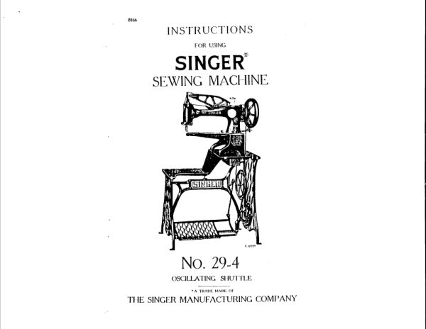
SingerPDF
Singer 29-4 (black and white scan)
User manual
7 pages · EnglishRead →

SingerPDF
Singer 29-4 parts list
Parts list
18 pages · EnglishRead →
SingerPDF
Singer 29K parts list
Parts list
34 pages · EnglishRead →
SingerPDF
Singer 29k58 & 29k62
User manual
33 pages · EnglishRead →
SingerPDF
Singer 31-19 & 31-47
User manual
20 pages · EnglishRead →
From the ISMACS International. Original publisher and archive notices are retained.
Check the model and edition against your equipment.
PDF verified 2026-10-11.