Sewing machine accessories
Singer B.U.K. Electric Motor (1931, foot control) — User manual
User manual for Singer B.U.K. Electric Motor (1931, foot control). 20 pages in English. Read the original PDF, download or print a copy without registration.
20 pagesEnglish1.7 MB PDF
Loading your manual…Open PDF directly
Document details
- Brand
- Singer
- Model / document
- Singer B.U.K. Electric Motor (1931, foot control)
- Document type
- User manual
- Language
- English
- Pages
- 20
- File size
- 1.7 MB
- Category
- Sewing machine accessories
- Document date
- Not specified in catalog
Search available document text
Find a term, then jump to its page in the original PDF. Image-only pages may not be searchable; check the PDF for exact wording and diagrams.
Page 1 · Read text
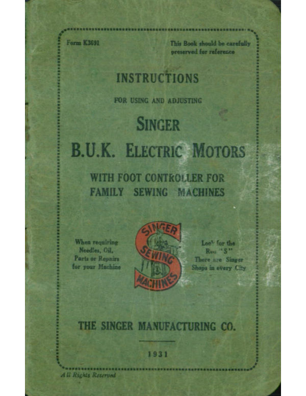
Form K3691                                     This Book should be carefully
                                   preserved for referesce

        INSTRUCTIONS


             FOR USING AND ADJUSTING


          SINGER

 B.U.K. ELECTRIC MOTORS

     WITH FOOT CONTROLLER FOR
     FAMILY SEWING MACHINES


              INSER

                                              Loe! for the    When requiring
      Needles, Oil,                      Reu "S"

    Parts or Repairs                                           There are Singer
   for your Machine                        Shops in every City

               MACHI


   THE SINGER MANUFACTURING CO.


                1931


All Rights Reserved
View original page 1Page 2 · Read text
USE ONLY SINGER
    LUBRICANT FOR
     ELECTRIC MOTORS


  THE BEST IS
   THE CHEAPEST


We prepare a specially
compounded lubricant

for use with our motors
SINGER LUBRICANT

is supplied in small tubes


     TO AVOID TROUBLE
     USE SINGER MOTOR
     LUBRICANT ONLY
View original page 2Page 3 · Read text
The Singer B.U.K. Sewing Motor.
   THIS efficient motor has been specially designed
     for the operation of Singer Family SewingT
     Machines, its speed being at all times under
the perfect control of the operator.

    Instructions for Attaching the Motor.

   First remove the machine belt, then fix the motor,
by its supporting bracket, to the back of the machine
arm.
  To fit the bracket, remove the japan from the
edges of the tongue (A, Fig. 1) on the machine arm,
over which the slot in the motor bracket will fit.


                       B


                            K 2578

         Fig. 1. Removing Japan from Tongue.
View original page 3Page 4 · Read text
2
This is necessary so that the bracket will slide up
and down freely.

  Place the motor bracket on the tongue, as shown
in Fig. 2, so that the hole (B, Fig. 1) in the centre
of the tongue can be seen through the slot (C, Fig. 2)
in the motor bracket; then insert the screw (D,
 Fig. 2) and, after moving the motor upwards as
 far as it will go, tighten the screw.


                                        K 2624

           Fig 2. Placing the Motor in position.
View original page 4Page 5 · Read text
3
            Putting on Fabric Belt.
    Place the fabric belt over the top of the balance
  wheel into the groove at its back, as shown in Fig. 3,
  and then force it into the groove in the motor pulley,


                                              K 2579


              Fig 3. Putting on Fabric Belt.

  in the manner shown in Fig. 4. The latter is easily
  accomplished by placing the belt half over the motor
  pulley (E, Fig. 4) and holding it firmly in position

with the thumb and forefinger of the right hand;,
  • a slight turn of the balance wheel will then cause
  it to spring into position
View original page 5Page 7 · Read text
5
       Regulating the Belt Tension.
  To adjust the belt tension, loosen the screw (D,
Fig. 5); this will allow the motor to drop down-
ward. Now firmly retighten the screw, and the
belt will be found to have the correct tension.


                                                 2625


          Fig. 5. Regulating the Belt Tension.
View original page 7Page 8 · Read text
K 2582


             Fig. 6. Applying the Singerlight.

        Applying the Singerlight.
                   (See Fig. 6)

  Remove the screw (M, Fig. 6) which holds the
cover plate (P, Fig. 6) in position, and place the
ring bracket (N, Fig. 6) over the opening, having the
two small lugs (O, Fig. 6) in the position shown.
These lugs are intended to maintain the Singerlight
in the horizontal position. Place the cover plate
(P) over the ring bracket and insert the screw (M)
through the holes in both and into the hole in the
arm of the machine. Turn the cover plate down
to its normal position, and retighten the screw.
View original page 8Page 9 · Read text
7
             Electrical Connections.
  The motor, controller. and Singerlight are
supplied fitted with flexible cords for making the
necessaryThese connectionselectrical connections.are made as follows :
  Remove the terminal block (R, Fig. 7) by taking
out the screw (S, Fig. 7). Then remove the three


                                    K 2626

                          Fig. 7.

insulated thumb nuts (U, Fig. 8). It will be noticed
that the terminal block has three screw posts, and
that those to the outside have distinctive coloured
spots against them.
  The leads for the motor are coloured red and
black.The eyelet of the red lead should be placed
on the post nearest the red spot, and the eyelet of
the black lead on the centre post.
   Place the eyelet at the red end of the Singerlight
lead on the post nearest the red spot and the eyelet
of the yellow end on the post nearest the yellow
spot.
View original page 9Page 10 · Read text
Replace the three thumb nuts (U), tightening the
latter securely ; then, with the screw (S), fasten the
terminal block to the motor bracket, as shown in
Fig. 7.


                   •
                            K 2627.

              Red Black Yellow
               Fig. 8. Attaching the leads.
View original page 10Page 11 · Read text
The wire lead for plugging into the supply, as also

the lead for the foot controller, are attached to the
socket plug, as shown in Fig. 9.


               K 2678


                   Fig 9.
View original page 11Page 12 · Read text
10


             Foot Controller.

  The foot controller. should be placed on the floor
in a convenient position for the user's right foot.


                   Speed.

  The speed of the machine is at all times under
perfect control. Pressure of the foot on the lever
of the foot control will set the machine in motion,
the speed being regulated by the amount of pressure
applied to the lever.
  Speeds varying from bare movement up to 1000
stitches per minute can be obtained, as required
by the work in hand. Immediately the pressure
on the lever is withdrawn, the machine will stop.
 It is not necessary to touch the balance wheel as
the machine will always start in the right direction.
View original page 12Page 13 · Read text
11
         Embroidery and Darning.

   For embroidery and darning, the machine requires
  to be operated at a low speed. Light pressure of the
 foot on the foot control lever will set the machine
 in motion at a low speed suitable for the convenient
 handling of materials being darned or embroidered.

  To prepare the machine for this work, remove
 the presser foot and raise the presser bar. Then
 adjust the stitch-regulating screw, so that the feed
 will be inoperative.

    It is advisable that the throat plate be covered
 with the supplementary plate made for the purpose,
 and it is essential that an embroidery hoop be used
for clamping the material. The purpose of the
 latter is to keep the work taut and to permit of it
being conveniently moved backward and forward
and from side to side by hand between the stitches.

  Feed cover plates and wooden hoops can be
obtained at any Singer Shop or of any Singer sales-
man at small cost.

  Darning by machine, when well done, is almost
imperceptible. It is far stronger and better than
hand work, and is much more quickly executed.
View original page 13Page 14 · Read text
12

  W           W


                                        K 2581

                         Fig. 10.
        To Lubricate the Motor.
  When sent from the factory the motor is lubri-
cated sufficiently for approximately six months' use.
 A tube of Singer Motor Lubricant is furnished
with each outfit. This tube has a tip which will
 fit into the two lubricating holes (W.W., Fig. 10)
leading to the motor bearings.
  Never under any circumstances apply oil to
any part of the motor.   Singer Lubricant, which
 is specially compounded for use with Singer motors,
 will remain just where it is wanted in the motor
bearings, while oil would work its way into the com-
mutator and brushes, giving rise to considerable
 trouble and vexation, such as difficulty in starting,
 over-heating, smoking, etc.
View original page 14Page 15 · Read text
13
          To Remove the Bulb.

   To remove the bulb, hold the Singerlight socket
  tightly with one hand, and with the other turn the
  shade half-way round until the pin in the socket is
  opposite the slot in the shade collar. Then gently
  pull the shade forward and allow it to hang free,
 as shown in Fig. 11.


                Switch                           Socket   Bulb
                 Button      Pin                                  Pin


                                                                    1.2129


                             Fig. 11.


   Press the bulb into the socket, and, at the same
time, turn it away from the machine until the bulb-
pin is out of the notch. Then withdraw the bulb
and shade.
View original page 15Page 16 · Read text
14
         To Replace the Bulb.
  Pass the metal end of the bulb through the collar
of the shade, with the slot in the shade collar up-
ward.  Hold the socket tightly with one hand, and
with the other hand press the bulb into it, with the
bulb-pin in the slot of the socket. Next, turn it
towards the machine until this pin is in the notch ;
then slip the shade over the socket, with the socket-
pin in the slot of the shade collar. See that the
shade is pressed well home, so that the pin is
opposite the ridge in the shade collar. Then turn
the shade until it is at the top.

          To Light the Lamp.
  To obtain light, push the small knob on the top
 of the lamp over towards the lamp shade.
View original page 16Page 19 · Read text
THE IMPORTANCE OF USING
SINGER NEEDLES FOR YOUR
     SEWING MACHINE


You will obtain the best stitching
results from your sewing machine
if it is fitted with a Singer Needle.

            at

Singer Needles can be purchased
only from Singer Shops or Singer
Salesmen.


Singer Needles are contained in
Green Packets which bear the
famous red letter "S."
View original page 19Page 20 · Read text
THE SINC MANFG.CO


This Trade Mark, Embossed In Brass,
        is on the rm of every
       Singer Sewing Machine.
View original page 20Related documents and language editions
SingerPDF
Singer "Famous" Buttonholer Models C and D
Parts list
4 pages · EnglishRead →
SingerPDF
Singer B.U.K. Electric Motor (1930, knee control)
User manual
10 pages · EnglishRead →

SingerPDF
Singer Blind Stitch Attachment
User manual
20 pages · EnglishRead →
SingerPDF
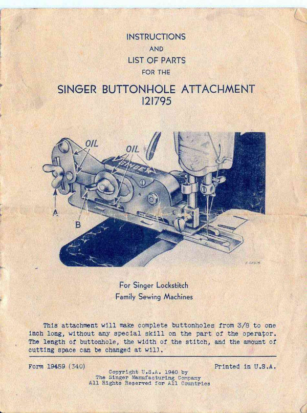
Singer Buttonhole Attachment Model 121795
User manual
16 pages · EnglishRead →
SingerPDF
Singer Buttonhole Attachment Model 121795
User manual
8 pages · EnglishRead →
SingerPDF
Singer Darning Foot Model 121094
User manual
4 pages · EnglishRead →
SingerPDF
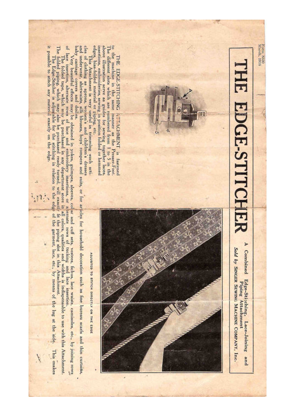
Singer Edgestitcher
User manual
4 pages · EnglishRead →

SingerPDF
Singer Flat-Work Darner
User manual
11 pages · EnglishRead →
SingerPDF
Singer Foot-Bar Attachments
User manual
20 pages · EnglishRead →
SingerPDF
Singer Hand Operated Pinking Machine
User manual
12 pages · EnglishRead →
SingerPDF
Singer Needle Threader
User manual
1 pages · EnglishRead →

SingerPDF
Singer Professional Model Buttonholer
User manual
16 pages · EnglishRead →
From the ISMACS International. Original publisher and archive notices are retained.
Check the model and edition against your equipment.
PDF verified 2026-10-11.