Industrial sewing machines
Singer Class 16 — User manual
User manual for Singer Class 16. 12 pages in English. Read the original PDF, download or print a copy without registration.
12 pagesEnglish1.2 MB PDF

Loading your manual…Open PDF directly
Document details
- Brand
- Singer
- Model / document
- Singer Class 16
- Document type
- User manual
- Language
- English
- Pages
- 12
- File size
- 1.2 MB
- Category
- Industrial sewing machines
- Document date
- Not specified in catalog
Search available document text
Find a term, then jump to its page in the original PDF. Image-only pages may not be searchable; check the PDF for exact wording and diagrams.
Page 2 · Read text
761

 USE ONLY SINGER OILS
                                  INSTRUCTIONS     and LUBRICANTS

  They insure freedom from lubricating trouble and                         FOR USING AND ADIUSTING
        give longer life to sewing equipment
                           SINGER SEWING MACHINES
  "Singer Oil for High Speed Sewing Machines"
                     (Cloth and Leather)
       For all manufacturing sewing machines excopt where a stainless
         oil is desired.

  "Singer Stainless Oil for High Speed Sewing Machines"
       For all manufnetaring sewing machines where a atainless oil is                        SINGER         desired.
"Singer Motor Oil"
       For oil-lubricated motors, power tables, transmitters and machin-
        cry in genernt.
"Singer Stainless Thread Lubricant"
        For lubrienting the needle thread of sewing nuchines for stitch-
        ing fobries or leather where a stainlens thread lubriennd is required.
      NOVT: All of the above oils are mailable in 1 quart, & quart, I gallon
       and l gallon, cans de in do gullon drums, and can also be sepplied
                                                                                                                    Machine 16-133

  "Singer Gear Lubricant"                                                            OF

        This specially propared grease is recommended for gent lubrien-
         1111001 919111191911019 461710 17710017704                          CLASS 16
"Singer Ball Bearing Lubricant"
                                                                        (CENTRAL BOBBIN)
        This pure grense ia specially designed for the lubrication of ball       brinos and out thrust beareus of motors and cicchie Mans-
          tallers, Dal beunne honece of power tables, cle
     NOTT:The above preones me famished in lath. labes and 1ll.
       aml 1, 10. lins.


                   Copyright,                               V. 8. A.,                                     1014, 1910, 1926                                                 and 1027,                 THE SINGER MANUFACTURING CO                      he thn minuer                                   minnmincturing                                             comonty
                          All Rightn Renerves for all Countrica
View original page 2Page 3 · Read text
To all whom it may concern:


facturing Company on any machine that has been repaired,                                                                          DESCRIPTION
materil, a so ted altered in i such sever                   Machines of Class 16, described in this book, each have oneis forbidden.                                                            needle and a central bobbin, oscillating shuttle and make the
                                                                         lock stitch.
                                                                       Machine 16-81 is especially designed for book and pamphle.
                                                                                        stitching. It makes stitches from to to te inch in length and will
                                                                                              stitch a book or pamphlet up do it inch in thickness. H has a drop
                                                                            feed and a roller presser.         THE IMPORTANCE OF USING
                                                                                Machine 1G-133 is intended for general work in cloth. I. ha:     GENUINE SINGER PARTS AND NEEDLES
                                                                             a drop feed and a presser fool.
             IN SINGER MACHINES
                                                                        Machine 16-141 is adapted for sewing cloth of light or medium
   The successful operation of Singer machines can only be                                                                     weight leather and is used for binding clothing, sandals, shor
i ad mie sils pact to podie are used Sing                  tongues,and carriagerubbertrimmingcoats, mattresses,and a greatlapvarielyrobes, ofcarpels,other automobilearticles, th
 Trade and mail orders will receive prompt attention.                                                                          binders being furnished, on order, at an additional charge. A
                                                                sample of the binding and the material to be bound should
                                                               accompany orders for binders. This machine is also useful for
                                                                                        stilching heavy buckskin gloves and leather gloves. H. has a drop
                                                                            feed and alternating presser feet.
                                                                           Machine 16-188 is designed for sewing cloth or light or medium
                                                                   weight leather and is used in the manufacture of automobil
        Company makes MiNco.",                                 curtains, waterproof covers, bags, tarpaulins, leather leggins,
                                                                               carriage trimmings, ele. This machine is equipped with upper
                                                                  and under feeding mechanism, each of which can be adjusted                   Needler in Containers marked
                     "For Singer Machines"                                      independently. By this means, the upper or lower plies of fabric
                     are not Singer made acedles.                                 can be fed faster or slower as may be desired.

                                                                             Binding, hemming and piping can also be accomplished on
                                                                         the machine, attachments for the various operations being
                                                                                 furnished, on order, at an additional charge.
View original page 3Page 4 · Read text
To Oil the Machine
   When the machine is received from the factory, it should be
 thoroughly cleaned and oiled.
    Oil should be applied at the places indicated by arrows in
 Pigs. 2, 1, 4 and 5, and whon the machie is in continuous use,
 it should be oiled at least twice each day.


                                                                                                           TAT. TND VEMOR ALACHINE, GHOWING GHANG THINK

            PIE. ORANG TOIT AT THE PRONT OF THE MACHIN
                                                                    Loosen the scrow (K, Fig. 4) near the upper end of the lac
                                                                                      plate, raise the plate and slip it off over the head of the sere:
   Loosen the thumb screw in the round cover plate on the back                 apply oil at the places designated by arrows in Pig. 4, then
of the machine, turn the cover plate up and oil the bearings                   roplace the lace plate and lasten it as bolor.
which are thus ancovered. the replare the cover.                             Turn back the machine on ils hinges and apply of i th
                                                                            Dlaces shown by arrows m kie. b
                                                                 Apply a drop of on to the shuttle bearing on the short fe
                                                                           cach ume a bobbm as replacod.


             PIG.. CLING LOINTS AT THE BACK OF THE MACHINA                                       HAse View or MaGane, CHOING OnANd ToINT
View original page 4Page 5 · Read text
Speed
                                                                     To release the balance wheel (1,, Fig. 6, page 6) turn the stup     The maximum speeds recommended for Machines of Class 16
  are as follows:                                                          motion serew (M, Fig. 6) over toward you. It will be necossary
                                                                                          to hold the balance wheel while loosening the stop motion sore.
         MACBINE
            16.91                               STITCUES191)PER MINUTE
            16-133                                 1800
           16-111
           16-188                                 1400                          toward you. This will start the band wheel, treadle and pitman.
                                                                                       the sewing mechanism having been disconnected.
    Run the machine slower than the maximum speed until the  parts which are in movable contact have become glazed by their
 action upon each other.                                                      Continue the motion thus begun by an alternate pressure of
                                                                              heel and too, until a regular and casy movement is acquired,
           Instructions for Operating the Machine                        and the balance wheel kept in continuous rotation by use of                                                                                  the feet alone.
     Raise the presser foot (6, Fig. 6) by means of the presser bar
                                                            When you are thoroughly familiar with the treadl movement,  lifter (J, Fig. 6) to prevent. injury tothe foot. (G) and feed (F, Fig. 6).                                                                     and can restart, the machine withoul turning the balanes wheel
                                                                                       in the wrong direction, lighten the stop motion sorew to connel
                                                                                     the balance wheel with the stitching mechanism.

                                                                                   Place a piece of cloth under the presser food or roller presser,
                                                                                                  let down the presser bar, and operate the machine in this way
                                                                            without being threaded, until you have become accustomed lo
                                                                             guiding the material.

                                                                   To Ensure Perfect Action of the Machine

                                                                       The balance wheel must always turn over toward the operator.

                                                           Do not. run the machine with the presser foot de roller pressor
              Mir 6. Those Sues of tre Macing                                       resting on the feed without eloth under the pressor food or coller
                                                                                            Miloser.
   When Machines of Class 16 are fitted with the stop motion
                                                         Do not run the machine when both bobbin case and moodleclamp serew (M, Fig. 6), the balance wheel (L, Fig. 6) can be released when required, thus enabling the operator lo become                    are threaded unless there is material under the presser foot. or
                                                                                               roller presser.
proficient in the use of the treadle, and permitting the winding of
bobbins without running the stitching mechanism. It also allows
                                                           Do not try to help the machine by pulling the fabric, lost. you
theworkoperatorand withoutto windunthreadingbobbins withoulthe machine.removing partially sewn                  bend the needle; the machine feeds the work without assistance.

                                                                     The slide over the bobbin case should be lept closed when the
                                                                       machine is in operation.
View original page 5Page 7 · Read text
11
               To Wind the Bobbin                                        To Thread the Bobbin Case
   Place the bobbin on the bobbin winder spindle and push it
on as far as it will go.
                                                                                    Hold the bobbin betworn the
                                                                                        thumb and forefinger of the right.
                                                                                                 hand, the thread drawing on top
                                                                                  from the lefl toward the right.
                                                                                                                                  (see Fig. 10).


                                                                                                                Tira. 10


                                                                  With the left hand hold the bobbin
                                                                                ease as shown in Fig. 10, the slot. in the
                                                                    edge being near the top, and place the
                                                                     bobbin into il.


                                                                                                                                              Mir. 11


   Place the spool of thread on the spool pin on top of the machine                                   Then pull the thread into the slot in
                                                                                                               the edge of the bobbin case (see fir. 11),and pass the end of the thread from the spool through the hole in
                                    Raise the bobbin winder                                     draw the thread down under the lensionthe side of the bobbin from the inside.
so that, its pulley presses against the rim of the balance wheel. (On                                           spring and into the delivery ayo ill the
                                                                                        end of the tension spring (see lig. 12).machines fitted with stop motion, release the balance wheel by
means of the stop motion thumb screw (M,Fig. 9) as instructed
on page 7). Then start the machine and at the same time hold the
end of the thread projecting through the side of the bobbin until
a few revolutions have been made.Guide the thread so as to fill                          Fi. 12
the bobbin smoothly and evenly. When suflicient thread has
been wound upon the bobbin, stop the machine, break the thread
and remove the filled bobbin from the bobbin winder spindle,
then push down the bobbin winder pulley.
View original page 7Page 8 · Read text
13
             To Renlace the Bobbin Case                                       To Thread the Needle
    After threading, take the bobbin case by the latch holding it                                                 (See PId. 11)
 between the thumb and forefinger of the left hand ; place the bobbin                        P'lace the spool of thread on the spool pm on top of the machine,
                                                                           pass the throad from the spool over between the thread rolainer


                                                167079


             TIGATO. BOMBIN TIRE THREADED AND KEPLACED


case on the centre stud (N, Fig. 8, page 2) of the shuttle body with
 the poston fnger opposite the notch at the top of the shuttle
 race, release the latch and press the bobbin case back until the
latch catches the smove near the end of the stud (sce fig. 13).
 Allow about. two mchos of taread to hang free.
                                                                                                                                                          1:1012
               To Set the Needle                                                                                  1'1. 141.Came cut Nesots

   Turn the balance wheel over toward you until the needie bar                   (ses 11) at the rear of the moper end of the lace Diate, dom mer
moves up to its highest point; looson the screw (B, Fig. 2, page 4)               from back to front betweon the tonsion dises (2) at. the Tont of
in the needle clamp and pul. the needie up into the clamp as far                   the lace piate, over the wue guide be above the tonsion discs, ini                                                                           the hook of the thread take-up spring (4),up and toward 1091
as le will go, with the long groove of the necdle toward the left.                 througn the hole in the ena on the thread lake up lever (6), down
and the eve of the noodle directly m une with the arm of the                through the wire thread guide (6) at the front of the face plale.
machine, then lighten the screw (1).                                             into the wire thread sude (o al, the lower end of the needle bar
                                                                 and from lelt to meht through the eve of the neodle (8). Draw
                                                                       about two inches of thread through the eye of the needke with
                                                                    which to commence sewmo.
View original page 8Page 9 · Read text
15
                                                                                    Tensions               To Prepare for Sewing
   With the left hand hold the ond of the needle thread, leaving                  For ordinary stitching, the needle and bobbin threads should
                                                                     be locked in the centre of the thiekness of the material, thus:il slack from the hand to the needle, turn the balance wheel over
                                        83800008
                                                                                                      Fro. 16. lensect Strici

                                                                                                If the tension on the needle thread is too tight, or if that on
                                                                                 the bobbin thread is too loose, the needle thread will lie straight.
                                                                       along the upper surface of the material, thus:
                                   0078337


                                                                                                 If the lension on the bobbin thread is too light, or if that on
                                                                                the needle thread is too loose, the bobbin thread will lie straight.
                                                                      along the under side of the material, thus:
                   P'ir. 15.DRAMNG DO THE BORBIN THREAD


toward you until the needle moves down and up again to its
highest point, thus catching the bobbin thread; draw up the needle
thread and the bobbin thread will come up with it through the
hole in the throat plate (see Fig. 15). Lay both threads back
under the presser foot.                                                  To Regulate the Tensions
                                                               The tension on the needle thread should only be regulated
                                                          when the presser bar is down. Having lowered the presser bar,
               1o Commence Sewing                                   turn the small thumb nut (A, Fig. 2, page 1) al the front of the
                                                                                 tension dises over toward you to increase the tension. To decrease
   Place the material bencath the presser foot or roller presser,                the tension, turn this thumb nut over from you.
lower the presser bar and commence to sew, turning the balance
wheel over toward you.                                            The tension on the bobbin thread is regulated by the serry
                                                                                           (1, Fig. 11, page 11) in the bobbin case tension spring. To incrase
                                                                         the tension, turn this serew over to the right. To decrease the
              To Remove the Work                                     tension, turn this screw over to the left.
                                                           When the Lension on the bobbin thread has been onee properly
   Let the thread take-up lever rest at its highest point, raise                                                                                   adjusted, it is seldom necessary to change it, as a correct stitch can
the presser bar, draw the work back and cut the threads close                usually be obtained by varying the tension on the needle thread.
do the material.
View original page 9Page 10 · Read text
17
          To Regulate the Length of Stitch                                    INSTRUCTIONS
                                                                   FOR
   The length of stitch is regulated by the thumb screw (C, Fig. 2,                      ADJUSTERS AND MACHINISTS
page 1) in the slot on the front of the upright part of the arm.
To lengthen the stitch, loosen the thumb serow (C) and move it.
downwardly. To shorten the stitch, loosen the thumb screw (C:)                    To Time the Needle with the Shuttle
and more it upwardly. When the desired longth of stitch has
                                                                      See that the needle is pushed up into the noodle clamp as far
been obtained, tighten the thumb serew (C).                                     as it will go.

      To Regulate the Pressure on the Material

   The pressure on the material is regulated by the thumb screw
(D), Fig. 3, page 1) on the top of the machine. To increase the
pressure, torn this thumb screw over to the right. 'To decrease
the pressure, turn this thumb serow over to the left. The pres-
sure should only be heavy enough to enable the feed to move
the work along evenly.


                                                            the shan the balance heed or lewed yon tie we te                                                                           of the needle bar.
                                         now so the shutle is this to pen the he she so o


                                                                                                                    it is at the required height, then sceurely lighten the screw.
View original page 10Page 11 · Read text
To Remove and Replace the Shuttle Race                             To lime the feeding Mechanism
   Turn the balance wheel over toward you unul the needle bar                  The feeding mechanism should be timed so that the food dou
moves up to ils highest point.                                                           starts its fooding movement away Irom the operator when tho
   Take out the two screws (K, Pig. 20) which hold the shuttle
race in postion and remove the shuttle race. Then remove the
shuttle from the shuttle race.
  When replacing the shuttle race, have the needie bar at ils
highest. point. and torn the shuttle in the race so that. it correctly
engages the shuttle driver, then securely fasten the shuttle race
1n position by means of the two screws (K.


           To Raise or Lower the Feed Dog

   The feed lifting rock shaft crank (S, Fig. 20) should be set so
that when it raises the feed bar to its highest point, slightly less


                                                                                               O6 6 00b! Go 61111121441

                                                                             needle bar commences its downward stroke.  The food should
                                                                        always finish is feedig movement before the noodle reaches tho
                                                                woods on is downward stroke
                                                       When it as nocossary to ume the loodme mechaman, orss
                                                                                the stitch regulator (C, Fig. 2, page 1) down to ils lowest point.
                                                                                for the lourest, sulch and lur un the round cover plate al. tho
                                                                      back of the machine. Loosen the feed eccontre set serer cli, fig.
                                                                             21) andturnthefeed cecentrie (V, Fig. 21) until the feed iscorrectly
                                                                                        timed asinstructed above, then securely tighten the so sore (1).
               TiG. 2O. ADJUSTMENT FOR KAISING AND LOWERING
                       THE NEED DOG


than the full dopth of the teeth project, through the slots in the
throat plate. To raise or lower the feed dog, loosen the clamping
 screw ('1', Fig. 20) and move the feed lifting rock shaft crank (S)
until the feed dog is sel at the required height, then securely
tighten the clamping screw ('1').
View original page 11Page 12 · Read text
To Adjust the Thread Take-up Spring
   The thread take-up spring (W, Fig. 22) should be sel. so that.
 when the eye of the needle reaches the goods on the downward


        AA                                                                  Conuino Sin So Mr Me hould ho unod
                                                                                         Theso Needles and thoir Contalnore
                                                                        Company"O marked ki*s MiNCO."

                           1/0/01                                                               Noodles In Containere markod
                                                                                                 "For Singer Machines"                                                                                                             are not Singer mado noodler.


stroke of the needle bir, the spring will be through acting and will
rest against the thread take-up spring regulator plate (Y, Fig. 22).
 Il the thread take-up spring is not coreetly set, loosen the set
screw (X, Fig. 22) which holds the thread take-up spring regulator
plate (Y) in position and lower the plate (Y) for more movement
of the spring, or raise it for less movement. When the spring is
correctly sot, securely lighten the sol screw (X).
   The tension on the thread take-up spring (W) is regulated by
loosening the set serew (AA, Fig. 22) at the side of the face plate
and turning the tension stud (7, Fig. 22) over toward you to in-
crease the tension, or over from you to decrease the tension. When
the desired tension is obtained, securely tighten the set screw (AA).
   The tension on the thread take-up spring should be just
suficient. to take up the slack of the needle thread until the cye
of the needle roaches the goods in its descent.
View original page 12Related documents and language editions
SingerPDF
Singer 11w6 & 11w8
User manual
13 pages · EnglishRead →
SingerPDF
Singer 13K
User manual
12 pages · EnglishRead →
SingerPDF
Singer 144w204, 144w304
User manual
28 pages · EnglishRead →
SingerPDF
Singer 145w103, 145w203, 145w303
User manual
24 pages · EnglishRead →

SingerPDF
Singer 16-188
User manual
45 pages · EnglishRead →
SingerPDF
Singer 17-22 & 17-23
User manual
12 pages · EnglishRead →
SingerPDF
Singer 29-4
User manual
17 pages · EnglishRead →
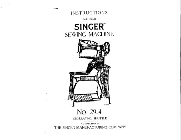
SingerPDF
Singer 29-4 (black and white scan)
User manual
7 pages · EnglishRead →

SingerPDF
Singer 29-4 parts list
Parts list
18 pages · EnglishRead →

SingerPDF
Singer 29K parts list
Parts list
34 pages · EnglishRead →
SingerPDF
Singer 29k58 & 29k62
User manual
33 pages · EnglishRead →
SingerPDF
Singer 31-19 & 31-47
User manual
20 pages · EnglishRead →
From the ISMACS International. Original publisher and archive notices are retained.
Check the model and edition against your equipment.
PDF verified 2026-10-11.