Heating & home equipment
Slant Fin Liberty oil fired boiler Equipment reference
Equipment reference for Slant Fin Liberty oil fired boiler. 20 pages in English. Read the original PDF, download or print a copy without registration.
20 pagesEnglish1.7 MB PDF
Loading your manual…Open PDF directly
Document details
- Brand
- Slant/Fin
- Model / document
- Slant Fin Liberty oil fired boiler
- Document type
- Equipment reference
- Language
- English
- Pages
- 20
- File size
- 1.7 MB
- Category
- Heating & home equipment
- Document date
- Not specified in catalog
Search available document text
Find a term, then jump to its page in the original PDF. Image-only pages may not be searchable; check the PDF for exact wording and diagrams.
Page 1 · Read text
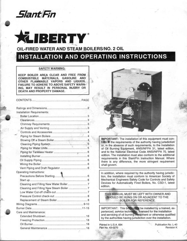
SlantlEn


                                                                                                                                                                               { q \  ftTBERTY'


                  SAFETYWARNING:
         KEEP BOILER AREE CLEAR AND FREE FROM
         COMBUSTIBLEMATERIALS, GASOLINE AND
        OTHER FLAMMABLE VAPORS AND LIOUIDS.
         FAILURETO ADHERETO ABOVESAFETYWARN.
           ING, MAY RESULTIN PERSONALINJURYOR
        DEATHAND PROPERTYDAMAGE.

         CONTENTS.....

          Ratingsand Dimensions.......                 .............2
                      Installation Requirements:
              BoilerLocation                               ..............3
               Clearances..............                             ......3
           ChimneyRequirements.........                .......3
               Air Supplyand Ventin9.............      ....................'3
              'Controls
                   and Accessories                     .............4
              Pipingfor SteamBoilers                      .......,.'......4
             BlowingOff a SteamBoiler.......         ....................4"   ^tlrlPOiTANT: The installationof this equipment must con-i                                                                                'f#1i16 the requirementsof the authority having jurisdiction'             CleaningPipingSysteqn....                    ............5                                                                                                     cir, in the absence of such requirements,to the Installation
              Pipingfor WaterUnits........                    ...........5        of Oil Burning Equipment,ANSI/NFPA 31, latest edition,l'iJ''
j             Pipingfor TankfessHeater           ..............1............6   and to the NationalElectricalCode ANSI/NFPA70, latest
               InstallingBurner.....                              .......6        edition.The installationmust also conform to the additionalt                                                            requirementsin this SlanVFinlnstructionManual.Where
I              Oil SupplyPiping                                ..........6      there is any difference,the more stringentrequirement
t            Wiringthe Boiler                                ...........6      shallgovern.
a.            Vent Pipingand DraftRegulator          ...................6
           Operatinglnstructions:                                                                               t                                In addition,where requiredby the authorityhavingjurisdic-
             PrecautionsBeforeStartin9........11,.......     .......6         tion, the installationmust conform to American Society ofIII?              Startup                        ...........':....      .........6      Mechanical EngineersSafety Code for Controls and Safety
                                                                 Devices for AutomaticallyFired Boilers, No. CSD-I, latestrI'            Cleaningand FillingNew WaterBoiler           .........7
                                           Boiler           ........7II            Cleaningand FillingNew Steam                                edition.
           Low Water Cut-offch6bk-out                      ........7                                                                AL MUSTBE LEFTWITH OWNERAND
             PressureControlcheck-out                       ..........I              BE HUNGON OR ADJACENTTO THE
            Replacementof SteamBoiler                      .......8                     REFERENCE.
           WiringDiagrams                              ...........9-10
          BurnerData........                         ........11-15    IMPORTANT:This Otl},il    be installedby a trained,ex-
          Care and Maintenance:                                   perienced,seruicetechnft,-ficensed for the installation
                                                         and servicingof oil burninffiuipment or otherwisequalified            ExtendedShutdown                                      ....16                                                                  by the authoritieshavingjurisdictionover the installation.
             FreezingProtection                                   .....16
               Oil Burner                                               ....16        Printedin U.S.A.694
            GeneralMaintenance...........                     ......16        Part No. 43-0270
View original page 1Page 3 · Read text
LIBERW                                                                                               3

BOILER LOCATION                                                   1. Cleanit.
Providea level.solidfoundationfor the boiler.Locationshouldbe              2. Inspectit thoroughly.
nearthe chimneyso thatthe FluePipeConnectoror Breechingto              3. Removeobstructions.
the chimneyis shortand direct.                                             4. Replacewornsectionsof metalstacks.
                                                                           5. Sealbad masonryjoints.
A. The foundationmustbe capableof supportingthe weightof the            6. Repairdamagedlinings.
   boilerwhenfilledwithwater:                                   C. Wheremorethan one appliancevents into a commonchimney,
                                                                   the area of the commonbreechingshould at least equal the
          Boiler      ApproximateTotalWeightol Boiler               areaof the largestapplianceflue plus 50% of the additionalflue
         Size          Assembly,filledwithwater                    areas.
                                                            D. Breechingarea must not be reducedat connectioninto chim-
        L-20             MO                              ney. Breechingmust be insertedinto, but not beyond,insideof
        L-30                   550                         chimneyliner.
        L-40                    660                           E. Chimneyheight shall extendat least 3 feet above where it
        L-50                    785                          passes throughthe roof of the building,and at least 2 teet
        L-60                    895                          aboveany ridgewitl'iin10 feetof the chimney.
        L-70                  1000                            F. The use of a vent cap, wherepermittedby code,givesaddition-
                                                                                al protectionagainstadversewindconditionsand precipitation.
B. The Liberty Boiler has full wet base sectionswhich surround      G. FlueConnection:Connectflue pipe betweentop of boilerand
   fire-boxfor maximumheat absorbtionof burningfuel, and low          chimney.Horizontalsectionsof flue pipe must be pitchedup-
   floortemperature.                                         wardto the chimneyat least 114'pet foot. Fluemustbe inserted
C. lf boiler is to be locatedover buriedconduitcontainingslectric            into,but not extendbeyond,the insidewall of the chimneyflue.
   wiresor telephonecables,consultlocalcodesor the National            Installdraftregulatorin flue pipe,as shownin figure3.
  Boardol Fire Underwriterslor specificrequirements.
                                                    AIR SUPPLY AND VENTING
MINIMUMCLEARANCE                                            Sufficientair for combustionand ventilalionin the boilerroommust
Provideaccessibilityclearanceol24' fuomsurfacesrequiringser-        be provided.Failureto do this will resultin poorcombustion,heavy
vicing(top and front)and 18"on any side requiringpassage.The          sootingand healthhazards.Any oil{ired boilermusthavea steady
boilershallbe installedwiththe followingMINIMUMclearances          draft'andan amplesupplyof combustionair at all timesduringfir-
fromcombustiblematerials:                                           ing. lf air supplyor chimneydraft-is unreliable,COeand overfire
A. CHIMNEYCONNECTOR.Is'                                           draft' will changeunpredictably.
B. BACK AND SIDES-6' EXCEPTas limitedby 18' cleannce
   from chimneyconnector                         DO NOT vent this boilerto the same chimneyflue used by a fire-
NOTE:Exceptin closetsand alcoves,clearancesabovein (A) and         place or coal or wood burningfumace or boiler.The draft' pro-
(B) may be reducedby providingformsof protectionas specifiedin       duced by solid fueleddevicesvaries tremendouslybetwesnhigh
NFPA31,latestedition.                                                           lire and lowfire:
CHIMNEYREQUIREMENTS                                        In modern,weatherstripped,energy-savingbuildings,naturalinfil-
A. The chimneymust be constructedh accordancewith all local         trationmay not supplyenoughair for combustion,particularlyif oth-
   applicablecodes and the NationalBoardol Fire Underwriters.      er fuel-burningappliances,exhaustfansor draftinducersare com-
  See boilermodelsand ratingtable shownon page 2 for chim-       petingfor the same air supply.Fireplacesand other solid fuel
  neysizes.                                           bumingappliancesconsumegreatquantitiesof air whileat high
                                                                                     lire;if air supplyis notample,suchan appliancewillcreatea down-B. Checkchimneycondition.
   Existingchimneysand stacksmay havedeteriorated;withoutre-         draft in the oil fired boilerflue: DO NOT operatethis boilerand a
   pairstheir use wouldbe hazardous.Beforeconnectingto an old        solidfuel burningapplianceat the sametime,unlessthe solidfuel
  chimneyor stack:                                            burneris providedwith its own outsideair supply.


                                                                                                                                 '00 r,loT IMiTALL mAFT RStIU-AT(nl€RE


                                                                                                                             id
                                                                                                                                    ^                                                                                                                                                                                                                                                                                                                                                                                                                   I
                                                                                                              Figure3.
                                                                                                    Barcmetic
                                                                                                                        Draft       BAROMETRICDMFT REGULATOR               BAROMETRICDRAFT REGULATOR                                                                                                            Regulator     INSTALLEDON HORIZONTALCONNECTOR              INSTALLEDON VERTICALRISE
View original page 3Page 4 · Read text
t l
                                                                                                                                                                                                '*$4 _                                                                                      ',IBERTY                                                                                                                                                                       $
FOR THIS BOILER ONLY, a grilled opening within 12' of the floor          D. Combustionsafety control -  mounted on burner.
near the boiler, direct to or ducted to outside,sized to 140 sq. inch              ll. WATER BOILER TRIM, see page 2 for tapping locations,and
per GPH nozzlesize, is recommendedfor air supply.lf such a direcl           figures1 and 2lor illustrationof water boiler.
outside air supply is not provided,COe and overfire draft must be           A. Pressure-temperature- Altitudegauge -  use tappingno. 6.
checked (refer to STARTUP) after closing all doors and windows          B. High temperaturelimit-  use tappingno. 7.
that will be closed on the coldestday, and operatingall fuel burning          C. Operatingcontrol(if used)-  use tappingno. 7.
appliancesincludingthis boilerfor at least 30 minutesof continuous         D. Water reliefvalve -  use tappingno. 3, piped full size to boil-
operation.                                                                        er.                                                               * ;
                                                                        E. Automaticair vent or compressiontank tappings-    if used,'
 lf fly screen must be used over air supply openings, areas calculated                installin tappingno. 2.
should be doubled;.thescreen should be inspectedand cleanedfre-            F. Combustionsafety control -  mounled on burner.
quentlyto maintainfree air flow.
                                                      PIPING FOR STEAM BOILERS
Protectair openingsagainst closure by snow, debris,etc. Openings       ProvideHeaderand HartfordLoopas suggested.See figures4 and
such as doors or windows,if used, must be lockedopen.                    5. Localcodes apply.
The openingsize recommendationiust given is for guidanceonly. lt      CLEANING PIPING SYSTEM
is an installationresponsibilityto provideair for combustionand ven-        A. To clean pipingsystem,open all valvesat the heatingelements.
tilationto all appliances,under all operatingconditions,for each in-           After gettingup a good head of steam,shut the boiler down and
stallation.                                                              allow the condensateto returnto the boiler.The condensatewill
                                                                         carry the oil film with it. Again blow-offthe boiler.On extremely'Draft        is negativeor suction pressure.                                     fouled systems,it may requireseveralvisits over a few days to
                                                                    clean the system.
INSTALLING CONTROLS AND ACCESSORIES                   B. When steam only (no wate| is releasedthroughthe hand valve,
ON BOILER UNITS                                                   the boilerwill not surge or flood.
Notes:  Jacket must be installedon boilerunits prior to installation
          of trim.                                          PIPING FOR WATER UNITS
                                                    NOTE: On knockdown boileronly,jacketmay be installedafter
l. STEAM BOILER TRIM, see page 2 for trappinglocations,and fig-       supplyand returnpipingconnection,but must be installedpriorto
   ure 4 for illustrationof steam boiler.                     r,                addingtrim.
   A. Steam pressuregauge and pressurecut-out,iristallin tapping            I. CIRCULATINGSYSTEM
      no. 4, figure4.                                                    A. FORCEDCIRCULATIONhot water heatingsystem: Use the
   B. Gauge glass set -  use tappingno. 12.                                 top tappingas supply tapping,and use the front or rear bot-
   C. Pop safety valve -  use tappingno. 3, piped full size to boiler;           tom tappingsfor the return.
      or pipe full size into a valvelesssteam header.                        B. A FLOW CONTROLVALVE (See figure6) will preventgravi-
                                                                                         ty circulationand usuallyis requiredwhen tanklessheateris
                          HI PRESSURELIMIT                                          installed.
                                                                                                      II. AIR CONTROLSYSTEMS
                                PRESSUREGAUGE                     A. DIAPHRAGM-TYPECOMPRESSIONTANKS aTe used to
                                                                              controlsystem pressurein an AIR ELIMINATINGSYSTEM:
   NIPPLE 1/l' x CLOSE                                                 an automaticair vent is used to REMOVE air lrom the sys-               :
                                                               tem water. See figure6.
                                                                                                                                      lf system pressureneeds further control,add an additional                                   I
                                    ELBOW                          tank or installa largercapacitytank.
                                                            1/4" x S"                      The automaticair vent should be installedin the top of the
                1/4'SYPHON                                                         boiler,as in figure6.
                                                                     B. CONVENTIONALCOMPRESSIONTANKS (non-diaphra$m
                                                                            type) are used to control system pressure in an AIR COL-
         TAPPING '4                                           LECTINGSYSTEM. Within the system, after initial start-up
                                                BOILERWALL             and venting,air is collectedin the tank and acts in contact
                                                                            with the water to controlpressure.Air is not ventedfrom this
                                                                     system.
                                                                                                                                     lf systempressureneedsfurthercontrol,add anothertank inFigure4.

                                STEAM                                                          STEAtvl                                 SUPPLY                                              SUPPLY                           il


                       NORMAL
                      YiIJRL E V E L   \  v
                          '?-_-\r--L                                  It t T^
                          251h',

              Y


                          RETURN                                   0                                LINE
                      ModelsL-50 thru L-70                       ModelsL-30 thru L-40

Figure5. Reommended&eam Pipingat biler
View original page 4Page 6 · Read text
6                                                                                                                                                                                    r rorow

VENT PIPINGAND DRAFT REGULATOR                          stacktemperatureshouldbe checkedand recorded.lf smokeis
A. Vent pipes must be installedhavingthe same diameteras the           greaterthan trace, reviewthe burnerinstructions;replacethe
   boileroutlet.(Seepage2.)                                        nozzleit necessary.Normalsmoketo be expectedat approxi-
B. Vent pipes and breechingmust be pitchedupwarda minimum         malely13oloCOzis zeroto a trace.
    of 1/4' per foot.C. Connectvent pipeto the chimneyusingas lew elbowsas possi-     CLEANINGAND FILLINGA NEW WATER BOILER    ia
   ble.                                                                                           I. BEFOREFILLINGWATERBOILER.
 D. Horizontalvent@nnectorinto the chimneyshouldnot be insert-          A. Check burnerto be certainit is ready for firing. DO NOT
   ed beyondthe insidewallof the chimney.                         FIREintoan emptyboiler.
 E. Installbarometricdraft regulatoron horizontalbreeching,near          B. Be preparedto heat raw waterto at least 180"F.as soonas
   chimney,with hingehorizontaland face vertical.See manufac-                       it is introducedinto the boiler.This procedurewill remove
    turer'sinstructionspackedin cartonwith barometricdraftregula-            dissolved,corrosivegases.
    tor.                                                         C. Providedrainline,with valve,from boiler.Use a bottomtap-
 F.  It two or more appliancesare used on the same chimney,see              ping.Lineanddrainmustbe suitablefor handlingcausticso-
  CHIMNEY,page3.                                                         lution.
G. Makeup alljointswithminimumair leaks,securewith                         II. CLEANINGWATERBOILERSYSTEM
      sheetmetalscrews                                            A. Preparea boil-out solutionol sodium hydroxide(caustic
                                                                    soda)or ti-sodium phosphate.
PRECAUTIONSBEFORESTARTINGOIL BURNER              NOTE:Use cautionin handlingchemicals.Causticsoda is
Makea positivecheckof A throughF beforestartingburner:                  harmfulto skin,eyesandclothing.
A. Boilerand systemare full of water.  All air is ventedfrom sys-               1. Proportions:1 lb. of eitherchemicalper 50 gallonsof sys-
   tem. Seebelow.                                              tem water.
B. All wiringis completed.See pagesI & 10.                                   2. Stir chemicalin water until dissolvedand pour into the
C. Oil supplyis connectedto the burner;nozzleis installedcorrect-                 boilerthrougha toptapping.Replaceplug.
    ly; oil valveis openat tank.                                       B. Fillthe entiresystemwithwater.
D. Smokepipeis connectedto chimney.                              c. Stanthe burner,usingthe start-upprocedure.
E. All combustiblematerialsare clearedaway.                           D. Circulatethe waterthroughthe entiresystem.
F. Combustionair supplyis provided.Seepage3.                          E. Ventthe system,includingthe radiation.
G. Burnersettingsare adjustedas per pages11-15and as shown           F, Allow boilerwater to reachoperatingtemperature,if possi-
  on boilerjacket.                                                         ble.
                                                              G. Continueto circulatethe waterfor a few hours.
  WARNING:NEVEROPERATEany naturaldraff boiler(Liberty          H. Shutoff the bumer.
   boiler is a naturaldraft boiler)with zero draft or overfirepres-          L  With CAUTION,drain the boilersolutionto a safe location.
   sure:earlyfailureof the burner,nozzleand chamberis inevita-        DO NOTLEAVESOLUTIONSITTINGIN SYSTEMOVER2
   ble if you do. Use a draft gauge,and make sure that overfire         HOURS.
   draf is .02',minimum,duringall operatingconditions.                    J. Wash the water-side of the boiler thoroughlyusing a high
                                                                  pressurewater stream. Fill and drain the boiler several    t    Draftis negativeor suctionpressure.                                times.
                                                                                                  III.TREATINGWATERFORCORROSIONCONTROL
STARTUP(COMBUSTTONTESTTNSTRUMENTSMUST             (Thisis not ScaleControl)
BE USED)                                                       A. Preparea solutionol sodiumchromate.                                                                                                                                                            jIA. Makesuretheboileris installedandwiredproperlyandis fu{lof              Proportions:6 oz. per 50 gallonsof systemwater.
   waler.                                                          B. Stirchemicalintowateruntildissolvedand oourintothe boil-           *
B. Openthe observationdoor (onthe front,abovethe burner).                 er througha toptapping.Replaceplug.
C. Startthe oil burner(see burnerinstructionsfor bleedingair from        IV.FILLINGANDVENTINGTHEWATERBOILER.    oil, etc.).IMMEDIATELY,set burnerair bandsto obtaina bright          A. Refillthe systemwithfreshwater.                                         {
   fire withoutsmokeor oil stain.Set the DRAFTREGULATORto           B. Bringwatertemperatureto at least180"F promptly.
   obtain.02" overfiredraft'. Take draft readingthroughslot in ob-
   servationdoor.                                     WATERCONTENTOF BOILER(GALLONS)                                                                                                                                                                                                                      *tD. Closethe obs€rvationdoor. Allowthe burnerto fire for at least                                                                            L-20   L-30   L-40   L-50   L-60   L-70  one hourtotalfiringtime,to bakeout the volatilebindersin the                                                         WaterBoiler   8.3   10.7  13.1  15.5   1 7 . 8  22.6  combustionchamberbeforetakingfinalcombustionreadings.
                                                                                                                                                                                                                                                                                                                                                I z . o    14.5E. By alternateadjustmentof the barometricdraft regulator,the        Steam Boiler           6.9    8.8   10.7
  burnerair regulationand headregulationdevices(whicheverap-
   ply), set for a trace of smokeand as closeto 13% COzas you                                      VOLUMEOFWATERIN STANDARDPIPEOR TUBE  can. Thenopen the air bandsor shutter(whicheverapply)an
   additional1/8'.Thisshouldresultin zerosmokewithNO rawoil                     Standard Steel Pipe      TypeL CopperTube  on the smokepaperand a smoothlight-off.DO NOTATTEMPT
  TO SETFIREBY EYE.Flameretentionburnersmayappearef-                                                             Nominal                   $i!g:   ficient and smokefree from an inefficient7o/oup lo an ovedy                                                                  Pipe            Inside   Gallons  Inside   Gallons   high 14%COz.However,a very low COecan also resultin poor                                                                    Size   ichedule Diameter   per      Dia.      per
   ignitionand raw (unburned)oil enteringthe fire box.At very high         lnches    No.    Inches   Lin.Ft.   lnches    Lin.ft..
  COz,any slightdecreasein air flowfor any reasonwillcausein-
   completecombustion,with highsmokeand dry sootformationin         318                             0.430   0.0075
   thefirebox.                                                  1t2     40    0.622   0.0157  0.545   0.0121
F.  lf smokereadingis satisfactory,but COecan not be increased          5/8                            0.666   0.0181                       '(12o/o   to a satisfactorylevel      ot better)or ovefire draft of 0.02'           3t4      40    0.824    o.0277   0.785   0.0251
  W.C. can not be obtained,checkfor propersealingbetween        1       40    1.049   0.0449   1.025   0.0429   sections,between bumer mountingplate and front section,         1 114    40    1.380   o.0779   1.265   0.0653  $  aroundburnerblasttubeand aroundfluecollectorandcollar.ll          1 1t2    40    1 . 6 1 0   0.106   1.505   0.0924   seal is not satisfactory,resealwith furnaceputtyor siliconewith         2       40    2.067    0.174   1.985   0.'t61 o
  a temperatureratingof at least400' F. (All safetyprecautions        2'v2    40    2.469    0.249    2.465
View original page 6Page 7 · Read text
q
                                                                                                                                                                                                                                                               !l.4
 LIBERTY                                                                                                                                                                                                                                                         {{
   c. Circulatewaterfirough ehtiresystem.                       down one to two inches below skimmertapping.The water
   D. Ventthe system,includingthe radiation.                         mightbe hot. Removeskimmerplug slowlyand carefullyinstall
    E. The boileris nowreadyto be put intoserviceor on standby.         a 150psi malleableiron 1-112'NPTstreetelbow,a 1-112'NPT
    F. lf brand-nameair-controldevicesare used,ventinginstruc-        skimmervalve and length of pipe and place a bucketunder-
       tionsfumishedwiththe devicesshouldbe followed.                neaththe open end of the pipe. Cover bucketwith a pieceof
 V. SAFETYCHECKFORCONTROLSYSTEM                             cloth.(Seefigure9.)
    Highlimitcontroltest Setthermostathighenoughfor boilerwa-       C. Fill boilerslowlyuntilwaterlevelis two inchesfromtop of gauge
     ter temperatureto reach high limit controlsetting. When this           glass.(Ihis is the startingwater level for skimmingonly). Fire
   temperatureis reached,the high limitswitchshouldopen,and            boilerto producesteam.lf the systemis heavilyladenwithoil, it
    the burnershouldshut off automatically.lf the high limit does        may be difficultto obtainmuchmorethan a poundor so of pres-
    notoperateto shutoff the burner,the highlimitor the wiringis           sure. Set the pressurecontrolat about 7 psi. The higherthe
     faulty.Repairor replaceimmediately.                          steampressureyoucan use,the betterand fasterthe cleaning.
                                                             D. As steamdevelops,opsn the SKIMMERdrain valve with cau-
 CLEANINGAND FILLING A NEW STEAM BOILER                    tion to skim the oil and film from the top of the water.DO NOT
  I. BEFOREUSINGSTEAMBOILER.                            openthe boilerdrainvalve.Closethe skimmerdrainvalvewhen
    A. Checkburnerto be certain it is ready for firing. DO NOT          the water level drops to about 5' from the top of the gauge
     FIREintoan emptyboiler.                                         glass.The watermay stopbeforethe leveldropsto 5' belowthe
    B. Be preparedto heat raw waterto at least180"Fas soonas it          top of the glass.Refillboileruntilwaterlevelis againtwo inches
        is introducedinto the boiler.This procedurewill removedis-          fromthe top of the gaugeglass.
      solved,corrosivegases.                                     E. Repeat(D) aboveuntilall film is skimmedoff and the waterset-
   C. Providedrain line, with valve,from boiler.Use a bottomtap-            tles to a normalmovement.Add makeup freshwaterto the boil-
      ping. Line and  drain must be  suitable for  hand-           er as describedin (D) above,duringthe blow-offoperation,to
       lingcausticsolution.                                        maintainthe properskimmingwaterlevelin the vessel.Empty
   D. Checkfor low water cut-offoperation,see sectionbelowfor          bucketfrequentlyin orderto see the ditferencein watercleanli-
     checkout.                                                 ness.
 II. CLEANSTEAMBOILERSYSTEM.                               F. Whensurginghas stoppedand wateris clean,and no film can
   A. Fillthe boilerto waterlineindicatedon theboiler.                 be seenfloatingin the bucket,shutoff boiler,draindownto level
   B. Followstart-upprocedurefor burnerand operatethe boiler           of skimmertapping,removevalve,plugskimmertappingahd re-
      with steamin the entirs systemtor 2 or 3 days to bringoil                  filfthe boilerto24-1/2'waterlevel.
     and dirt from the systemto the boiler.Whilesystemis in op-            After15 minuteoperation,readjustlevelto normaloperatinglev-
      eration,maintainthe properwaterlevelin the boilerby slow-            el ol 25-112'frombottomof boiler(seefigure9). Checkthe pop
        ly addingwaterto lhe boiler.                                      safetyvalvefor properoperation.
   C. Shutdownbumer,cool downboilerand drainsystem.             Checkfor low watercutdf operation,see nextpage.
   D. Procedureto dissolveoil andgreasein boiler:                 G. The entireprocessmay haveto be repeatedover a periodof a
       1. Fillboilerto properwaterline.                              tew dayson extemelyfouledsystems.
 .      2. Preparca boil-outsolutionol sodiumhydroxide
         (causticsoda)and tri-sodiumphosphate:                    POPSAFETYVALVE      FLUE PIPE
       NOTE:Usecautionin handlingchemicals.Caustic
       sodais harmfulto skin,eyesandclothing.                      CTAUGEGL SS                        STARTOF SKIIMIT.IG
       .     (a) Proportions:1 lb. of eachchemicalper 50 gallons of                                        TOPIEVEL.OF GAUGE? BELOWGLASS
          systemwater.
          (b)                           into                          water              Stir              chemicals                                         untildissolved                                      and                                             pourinto                   I                                                                                                                   1 I/z MALLEABLEIRoN                                              plug.           the                boiler                  through                       a                           top tapping.                                 Replace      3. Startthe burner;boilthewaterfor at least5 hours;                T 150PSISTREETELBOW
        shutoff the burner.                                                                                                                                                                                 I lrr SrhrttvtER
   E. With CAUTION,drainthe boilersolutionto a safelocation.            2s 1l?                               DRAINVALVE
                                                                                       COVEREDBIrcKET    DO NOTLEAVESOLUTIONSITTINGIN SYSTEMOVER2         OPERATINGNORMAL
    HOURS.                                            WATER
   F. Wash the waterside of the boilerthoroughlyusinga high          LEVEL
     pressurewater stream.  Fill and drain the boiler several
      times.
III.TREATINGWATERFORCORROSIONCONTROL
   (Thisis notscalecontrol).
   A. Preparea sofutionol sodiumchromate.                                                                  Figure9,      Proportions:1 lb. per50 gallonsof boilerwater.
   B. Stir chemicalin water until dissolvedand pour into boiler
     througha toptapping.Replaceplug.                 LOW WATER CUT.OFF CHECK.OUT
IV. FILLINGANDVENTINGTHESTEAMBOILER.                        Electronicprobetype low water cut-off. lf this boileris factory
   A. Refillthe boilerto the indicatedwaterline.                       equippedwith an electronicprobetype low watercut-otf,opera-
   B. Bringwaterto boilingtemperature,promptly.                           tion ol cut-offshouldbe checkedat leasttwicea year as follows:
   C. The boileris now readyto be put intoserviceor on standby.           A. While boiler is running, drain down boiler water slowly
                                                               throughBoilerDrainCockshownon page4, just untillight
                                                          goeson. Boilershouldshutdown10 secondsafterlightgoesBLOWING OFF A LOW PRESSURESTEAM BOILER
A. A 1-112'NPT tappingis providedin the front of the boiler(tap-            on.
   pingno.9, figure1) for use as a surfaceblowdownto provide          B. Be surethat it is the low watercut-offand not the roomther-
   rapidskimmingof oil and greasewhichaccumulateon the sur-             mostat,pressurecut-out,or other controlthat has shut-off
   face of the water. The boilershouldbe blowndownas outlined            the burner.
   below.                                                      C. Refillthe boilerand repeattest.
B. Turn off electricalpower supply to boiler.Allow boiler to cool          D. Refilltheboilerand resetcontrolsfor normaloperation.
  down and steam pressureto reduceto zero beforeremoving             il. Floattypelow watercut-ofl
  skimmertappingplug.Checkfor steampressureby testingthe                  lf this boileris factoryequippedwith a McDonnell& Millerfloat
  pop safetyvalve. Keep your handsand all parts of your body          type lowwatercut-ofi,the low watercut-offmustbe blowndown
                                                                     (flush
View original page 7Page 8 · Read text
LIBERTY
 CAUTION: When flushingtloat type low water cut-offcontrol,     PRESSURECONTROL CHECK.OUT
  hot water and steamwill flow out the blow down valve. Blow       A. Checkbumerto be certainit is readyfor firing. DO NOT FIRE         \
 downvalveis illustratedbelow.                                           intoan emptyboiler.
  A. SPECIALFLUSHINGINSTRUCTIONS                       B. Set thermostathigh enoughfor boilerto make steam. Set the    Fornewboilerinstalledin old system.                           pressurecontroldownto its lowestsetting. As the boilerstarts  I
     Installationof new boilermay breakloosea heavyaccumula-           to producesteam,the steampressurewill start to build. The
     tionof sedimentand scalefromold pipingand radiators.lt is          burnerwill shut-offwhenthe steampressureexceedsthe pres-
    extremelyimportantto blow down your McDonnellcut-off          suresetting(plusdifferentialif controlhas this feature).
    morefrequentlythe firstweek.                              C. Adjustthe pressurecontrolto a highersetting.The higherset-
    Firstweek-3times                                               ting shouldbe abovethe steampressurein the boiler. This
    Thereafter-  at leastoncea week.                            shouldturnthe burnerbackon.
  B. As boilerwater circulatesthroughthe float chamber,dirt or       D. Resetthe pressurecontrolas neededfor the system.The pres-
     other sedimentmay be deposited. This chamberis extra          surecontrolshouldbe checkedat leasttwicea year.
    deep. But the only sure way to keepany accumulafonfrom
     interferingwith float actionis to "blowdown',or flushout,the     REPLACEMENTOF STEAM BOILERS
    controloncea week.                                    Anytimean oldersteamboileris removedfromthe heatingsystem
   Do it whileboileris in operation.First notewaterlevelin       and replacedwitha new boiler,thereare certainconditionsthat
    gaugeglass. Openblow-offvalveat bottomof control;water       haveto be examinedon the heatingsystem.
     will pour out, flushingaway sediment. Drainuntilwateris        A. Steamsystemshavea tendencyto developscaleinsidethe wet
    clear-  abouta pail -  then closevalve. lf levelin gauge          returnlinesandthe boiler.The olderthe systemthe greaterthe
    glasshas dropped,add waterto boilerto restorelevel.              accumulationof scalethat can existinsidethe piping. There-
 C. NOTE: Openingblow-offvalvecheckscut-offoperationtoo.            fore,it is necessarywhenreplacinga steamboilerto checkthe
   As float dropswith fallingwaterlevel,burnerwill stop. After          pipingfor blockageor restrictions.Cleanor replacethe piping
    burneris off and normaloperatingconditionsrestored,burn-         as required.(Seespecialflushinginstructionsabove.)
    er will resumefiring.                                       B. Replaceall buriedwet returnlines.
 D. Be sure that it is the low watercut-offand not the roomther-       C. All equipment(airvents,radiationequipment,etc.)in the steam
    mostiat,pressurecut-out,or other controlthat has shut off          heatingsystemshouldbe checkedfor properoperation.All pip-
    the burner.                                                   ingshouldbe checkedfor properpitch.
                                                          D. lt is goodengineeringpracticeto repackor tightenthe packing
                                                              nutson all valvesin the heatingsystem.

STEAMCONTROLASSEMBLY                                                                                                      NIPPLE
InstalledMcDonnell& Miller67 lowwatercut-offandwaterlevelgauge.8'F;l",,J"*                                                                    j'   5. rxo


  SPECIALFLUSHINGINSTBUCTIONS                           o  Installation              ot new boiler                   may                                 loose                          break                                     a heavy                                            accu-                                                                                ruee  mulatron                                      piping            ol sediment                  and                        scale                            lrom old                                     and radia-                                                                                                  |b.o.
  tors.ll rsextremelyimportantlo blowdown your McDonnell                                                                                                                     {
  Cut-olfmore lrequentlythe lirst week.                        LOV' WATER
  Firstweek-3 times                                CUT 6F                      UATER LE\€L
  Therealter-at least once a week.
 See CARE & MAlNTENANCE sectiontor inslructions.
                                                                             WATER LEVEL GAL'G€


                          BLOWDOWN--------------->
                        VALVE
                                                                         DRAIN PIPE
View original page 8Page 16 · Read text
16                                                                                  LIBERTY

CARE AND IIAINTENANCE                                                          II. PrcUDNG PrcTECTIONFORFREEZING
l. EXTENOEDSHUTDOWN,OR REIvIOVALOF BOILERFROM           Anti-freezeis sometimeeusd  in hydronb heating systemsto
  SERVTCE.                                                        probct againstfreeze-upin the event of ponuerfailure,or safety
  A. Flushsltdge from botbm of bdl€r. Whil€$e boileris stillhot            controlshudownwhen the buiklingis urneupried.lt shouldbe
     (180" to 2@" F), drain water trofn the bottom of he boilor          reognized that unlessthe buildingis kept abovefreezingtem-
       untilit runscbar.                                                p€rat.neby somem€ans,he plumbingsystemis not protected.
   B. ProvirJeconosion protectionb wat€r (this is not scah con-
      rol):                                           Two Spes of anti-fieezemay be used: ETHYLENEGLYCOL,                                                                                                                                                                  -tr      1. For steam bclilers,maintain a sodum chrynala.solut'nn         used in automobiles,has desirableprops,rti€s,but is toxic. lb
       sbengthof 16 oz. per 50 gallonsof wator;and refillto the          uss may be prohibitedwhen sysbm water/glycolsolufronis in
      Op of the gaugeghse.                                         contactwith a potrablewater vessel (as with a tianklessheabr).
      2. For wabr boibrs, maintain a sodum chromatesolutinn       PROPYLENEGTYCOLis used in tre quick-freezetood indus-
        stenglh of 6 oz. per 50 gallonsof wabr, and refill to nor-               fy;   it is prrcti<;allynon-toxic. lts use may be permitrd when
       mal fill-pressurewitrsysom wnted.                             tanklessheatersare us€d.When anti-freezemust be used,in-
      3. Raisewetertemgeraur€to at least 180"Ffor one hourto            hibitedpropyl€rnglycolie rscomm€nded.Usefulinformationon
        releaseclssolvedgases.                                                           .   the characteristics,mixingproportions,etc. of glycolin heating
      4. Strutdownbumerby dsconnectingthe mainswitch.         _   : systsmsis given in TechnicalTopicsNo 2A, availablefrom tre
  C. Cleanboilerheatingsurfacesthoroughly,dorvno cleanmet-              . . HydronicsInstitub, 35 Russo Place, Berkel€yHeights,N.J.
      al.                                                                                 -  07922.Consultglycol manufacturersfor souroesof propylene
      1. Remow flue and c-leantroroughly.                              glyool.                                                                                                                                               '   *      2. Remow bp flue colleaor b facilitab cleaning soot and
       scah from the heatirB eurfms.                       n    ltiJo|LTBURNER
       To remove the frue collector, the top rear jacket panel           Inspgctand dean annuallyand bllowingany pefud of improper
       mustftrstbe remowd. The ffue collectoris heH in place           operation.Recfi€ck and adjuet setings as specifiedfor burner                                                                                                                                                          '       by a single caniage bolt and wing nut at tre rear of the         modelard nozzlesize.
         boiler. Removethe wing nut and pull up firmly on the           Sst bumer air ard draft rcgulator,using test instrumentsb ob-
         rear of he frue colledor tipping it forward to keak the             trainreommendedCOzand draftwithoutsmoke.Referto pag€                        i
        seal betweenit and the boiler. Then,pull it out from un-           6.
        der th€ lip in the front bciler section.
           gain                                                                      IV.                                               GENERAi                                                       IUAINTENANCE              ac€ss                         to                         the                         combUstion                                 chamber                                                        for deaning,      .3. To                                                                                                                                        I                                                          These                                                                           operations           burner       he               must                    bs                      removed.                            The                                            flexibleelgcfical                                                                                  are recommend€dto be p€rformedat regular             {                                                aon-       *.'         duits frorn the burnerb the limit ontrols are long enough           inbnrals:
         to allowremovingthe bumerwilhoutdisconnectingthem.          A. BOILERHEATINGSURFACES:cleanoff all coatingsforqd.      ,   The cast iron burnermountingplao shouldbe remocd,.            Resealcovers.                                                                                                                                                              IiI       aloog wih the bumerto compl€tolyexposefre combus-          . ":.  B. BOILERCONTROLS:c*t€ckcontac-t6,settings,conectfunc-
          lion chamber for thoroughdeaning and foq inspectionof                .lioning.
        the targetwall.                                           C; PIPING:dreck p*5tingard accessoriesfor leaks.
      4. Use the flue brush b c-leanthe pinnedfluerrvaysb€tweon          D. CHIMNEYor STUBVENTand BREECHING:cfreckfor ob-
        the sections. A wire brush may be used to rcmoveany               struclionsand leaks.
       carbon aocumulatbn hat may have developed in the           E. COMBUSTIONAIR TO BURNER:checkfor continuedPO$
       combus$onchamber. Vecuumtre loose soot and debris            ITIVE supplyof air as required.Air needs are greatestin
        from he boiler.                                                 coldestweather.Refero AIR SUPPLY,page3.                                 :
      5. Insped fie refracbry target wall in he redr of the com-           F. WATERSYSTEM:check
        bustionchamber. lf bady deteriorat€d,it shouldbe re-               1. Sysbm b be full of w$r  and pressureto remainslable
        placed. Inspectthe bumer oombustionhead. Clean lf               (botween12 psi and 25 psi).
       necgssaryand make sure all the adjustmsntsarc con€€i.               2. Air-control'systsm:noise and air binding in racf,atkrn                            q       (See bumer data pages for the burner installed.) Re-               shouldnot occur.
       placeoil nozzlewith a new one. To insureproperburner ,              3. Waterlines:slighbstleaksshouldbe corrected.
       operationONLY THE NOZZLESSPECIFIEDlN THIS               4. Lowwatercutoff,for operation(see instructionsfumished
     MANUALOR ON THE BURNERI.ABELSHOULDBE                 with unit). See page7.
     USEDFORREPIACEMENT.                                  \         G. STEAMSYSTEM:check      6. Protsctall of dp firesidesurfacesby swabbingwih neu-               1. Lowwatercutoff,for operation(see insUuctionsfurnished J       Ual mineraloil.                                                        with unit). See page7.                   *l
      7. Replaceburnerand iue collecbr.                                      2. CheckF€ssurecut-oftfor opsration.See page8.
         In most casg6, tho flue collecbr €ealantcan be reused.                3. Any unusualwaterconditions.Obtainwater analysisand
       Smootr the sealant in the groove around he top of he                    treat wabr.
         boiler sectionsand under the lip in the front sec{ion. Be          H. BOILERRooM AIR SUPPLY:air wnts shouldbe ooenand                                                                                                                                                                                                                                                               li       sureftat trere aro no gap6.                                          free of obstruction.See pag€3.
      The hed of the caniage bolt frts into tho slot on tre bp
         of the rear seclion. Insert the front edge of the flue col-                        f  A flue brush(2-114'dia.)is suppliedwith boiler.Replace-               ;         lector under he  lip on the front section. Push forward            mgnb are availablefrorrrdeal€r or hardwarestores.
      and dovn on the flue collector,guidingthe bolt into f€
        bracketon he flue cotlector. Add tre washerand wi
View original page 16Page 20 · Read text
:


DETAILOF CLEANOUTAND
OBSERVATIONDOORASSEMBLY


Figure 3


                                                                              /t-                              br=,      na,;tL.r)                 SLANT/FINCORPORTATION,Slant,-,,,100 Forest Drlve, Greenvale, New York 11548 . (516) 484-2600
View original page 20Related documents and language editions

From the M. Butkus archive. Original publisher and archive notices are retained.
Check the model and edition against your equipment.
PDF verified 2026-10-10.