Film cameras
Petri MF-3 User manual
User manual for Petri MF-3. 27 pages in Spanish. Read the original PDF, download or print a copy without registration.
27 pagesSpanish4.0 MB PDF
Loading your manual…Open PDF directly
Document details
- Brand
- Petri
- Model / document
- Petri MF-3
- Document type
- User manual
- Language
- Spanish
- Pages
- 27
- File size
- 4.0 MB
- Category
- Film cameras
- Document date
- Not specified in catalog
Search available document text
Find a term, then jump to its page in the original PDF. Image-only pages may not be searchable; check the PDF for exact wording and diagrams.
Page 2 · Read text
F;N(; I,'SH
    Welcome to the excitrng world of PETRI You new camera is one of a fanrily of professional
                                              serious photographer in mind. And the name PETRlis your@  quality cameras designed with the     assurance of superbly crafted optics and outstanding mechanical performance and reliability.

          t,l:t 'fs('H
     Wir begrLifien Sie in der aufregenden Welt der PETRI. lhre neue Kamera gehort zur Famrlie der
      professionelleri Oualitatskameras, die unter Berr.icksichtigung cler Ansprtiihe ernsthafter Foto-@  grafen entwickelt wurde. Der Markenname pETRI  ist lhre Gewahr fur riberragende Optik,
     hervorragende Technik uncl Zuverlassigkeit.

       I.'RAN('AIS
     Bienvenue dans le monde passionnant de PETRl.Votre nouvel appareil photographique est un
@  modelele nomdedela PETRIfamille desest appareilspour vousde l'assurancequalit6 professionelle,d'une optiqueconcu superbementpour le photographetravaillee,averti.d'uneEt
     performance m6canique remarquable, et d'une robustesse insurpassable.


      ITAI.IAN0
     Benvenuti nel mondo eccitante della PETRI . La Vostra nuova macchina fotografica fa parte di
fn  una famiglia di macchine di qualitd professionale studiate tenendo presente lJesigerrze'del piu\y   serio {otografo. Ed il nome PETRI d l'assicurazione di un'ottica superbamente cbstruita, e di      prestazioni mecqaniche eccezional  i.


            l-;s t,ANr)1.
     Bienvenido  a'l mundo emotionante de la Su nueva camara pertenece a una familia de cdmaras de
A\:'   calidadY el nombreprofe'sionalPETRIqueeshansu srdogarqntfadisefradasde opticapensandoespl6ndidamenteen el fotografofabricadaserio.  y de funcionamiento
     mecanico destacado y de precisi6n',.*
View original page 2Page 5 · Read text
www.butkus.us


@ @(N)@


                                                 DN:ou=butkus.org,Date:cn=Mike2023.05.22signedButkus,email=mike@butkus.org,by10:59:47Mikeo=ButkusButkus-04'00'camera manuals,c=USMike Butkus    Digitally
View original page 5Page 7 · Read text
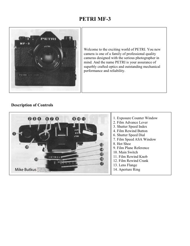
E.  Description of Controls
      1. Exoosure Counter Window
     2. Film Advance Lever
      3. Shutter Speed Index
     4. Film Rewind Button
      6. Shutter Speed Dial
     7. Film Speed ASA Window
     B. Hot Shoe
     9. Film Plane Reference
    10. Main Switch
    11. Film Rewind Knob
    12. Film Rewind Crank
    13. Lens Flange
               'l 4. Aperture Ring
    15. Aperture/Distance Scale lndex Line
    16. Depth of Field Scale
    17. Focusing Ring/Distance  Scale
    18. lhfrared Mark
    19. Shutter Release Button
    20. Lens Mount Release Button
     2'1. Selftimer LED
    22. Removable Door Hinge
    23. Cable/Remote Release Socket            3i. Film Advance Sprocket
    24. Carrying Lugs                           32. Film Take-up Spool
    26. "X" Sync PC Outlet                    33. Film Pressure Plate
    27. Film Chamber                            36. Tripod Socket
    28. Film Ape_rture                          37. Battery Compartment Cover
    29. Viewfinder                             38. Auto-winder Coupler
    30. Film Guide Rails                        39. Back Cover
View original page 7Page 9 · Read text
LFa-
       With the  f ilm rewind crank in the folded our      SETTING FILM SPEED        positron, rewind the  f ilm slightly to remove
      any slack in the film cassette. Recheck to        For properly exposed photographs. your MF-3's
      see that the film remains secured to the          electronically controlled metering system must                                                                                     DIN       take-up spool and that it is properly aligned        be set for the correct ASA (or DIN -  for
       with the Sprocket (31). Fold down rewind          equivalents,)  rating of film you are using.
        cran k.                                      To set the  f ilm speed:
     6.  Close the Back Cover (39) until you hear an         1.  Lift the col lar on the Shutter Speed Dial
       audible click, which indicates that the cover                (6).
          is locked in the closed position. Advance the         2. Turn the col lar until the ASA rating for
       film by  alternately winding the advance          your   fi lm appears in the ASA Window.
        lever and pressing the shutter release button               (Fis.4)
        until the number "1"  appears in the Film         3. Release the collar to lock the settinq in      Counter Window (1). As the advance lever is              ptace.
      wound, the film rewind knob should rotate,
       indicating that the film  is advancing pro-
       peny.


          Fis2                    Fis3                                 Fig4
View original page 9Page 10 · Read text
www.butkus.us                (DSHUTTER SPEED SELECTION
The MF-3 has a shutter speed range of 4 seconds                                 +oK-to 111000 second, plus "8"  (Bulb) for Time
Exposures. To set the shutter speed. turn the
shutter speed dial until the ciesired shutter
speed is aligned with the Shutter Speed lndex
(3). When using shutter speeds lrelow 1/30 of a
second, it  is a.dvisable to use a tripod and a
cable release or the dxclusive remote control ler
to eliminate the possibility of vibration due to                                      Fis5
the camera movement. The MF-3 is equipped
with a threaded Cable Release Socket (23) and
Triood Socket (36) for use with these acces-      FOCUSING THE CAMERA
son es.                                        Your MF-3's focusing screen includes a central
                                                   horizontal split-image rangefinder, which  is
TIME EXPOSURES                                surrounded by a microprism collar' (Fig.5)
When making time exposure photographs, your       To focus accuratelY:
camera should always be tripod-mounted and         1. Center the split-image rangefinder on your
used with a locking cable release. The MF-3's           key subject and turn the Focusing Ring ('17)
electronic shutter is capable of time exposures              until the upper and lower portions of your
of up to 4 seconds.                                           subject become one, clear vertical image.                                                     2. The surrounding microprism collar will   a)
For the time exposures of over 4 seconds in          appear   f ragmented when  the image  is
duration:                                                                 .    entirely out of  f ocus, b) appear shimmering
1. Align "8"  setting on shutter speed dial with           but viewable when image is nearly in focus
    the shutter speed index.                            and c) appears clear when your subject is in
2. Advance the film and press in on tip of            focus. lt  is especially useful when there are
   cable release to open the shutter. Turn the          I   no pronounced vertical lines on your sub-
   cable release lock to hold shutter open.                     i.    ject, making the use of the horizontal, split3. Af ter the desired exposure time in seconds         1,.', image rangefinder difficult'
   has elapsed, release the cable release lock to
    close the shutter.
View original page 10Page 11 · Read text
e 3. The entire focusing screen may be used for            turnecl to the direction  the  (+) illum-
      both focus and composition of your photo-            ination  or the shutter spee<l dial shoulcl be
       graph. The human eye tends to ignore minor           turned to the opposite drrection until  ttre
        differences in sharpness. Therefore, the hori  -       OK signal lamp lights.
       zontal split image rangefinder and/or the         8. The proper exposure of   f ilm is obtaineci
       microprism collar should always be used for           whenever the OK signal  lamp lighrs. The
         critical focus when possible.                          range that the OK signal lights is 0.3 EV.
                                                                                                                                                                                              is   METE R ING SYSTEM                       When a certain aperture size (F-stop number)                                                         desired because of the depth of field effect   Your MF-3 has the open-aperture, TTL center-         (refer to the next paragraph), set the desired
    weighted average, match LED metering system.         F-stop first and turn the shutter speed dial until
    Setting the exposure:                                  the OK signal illuminates.
    1. Advance the  fi lm.                        NOTE: When both red LEDs illuminare. you
   2. Set the Main Switch (10) to "ON". (Fig.6)        have gone beyond the cameras metering range
   3. Select a desired shutter speed by rotating       and should, if possible alter the aperture so that
        the shutter speed dial.                            a different speed can be used.
   4. Depress the shutter release button quite
        slightly so that one of the LED indicators in
       viewfinder illuminates.  ( F ig.7)
   5. The LED indicators will tell you whether
       the present setting is over, under or correct                                 Fis6
       exposure.
   6. When the red warninq lrght (+) lights rt  rs
      meanrng of Over-exposure. In this case the
                rl iaphragm ring of the taking lens should be
        turneLi to the (-)   illumination or the
       shutter speed clial shoulcl be turned tcl a
          Iri-oher speeri until rhe OK signal lamp
          ligh ts.
     I. When the red warning larnp (  )lights, it  is
       meanirrg of Under-exposure. In this case the
       riiaphragm ring of the taking lens should  lre                                                                         FigT
View original page 11Page 12 · Read text
www.butkus.us                          (e)DEPTH OF FIELD                      SELFTIMER
The aperture setting determines the near ancl       The self timer delays the tripping of the shutter
far areas in which items other than your key        mechanisrn for  approximately 10 seconds,
subject will  remain acceptably sharp. This        allowing you to include yourself in the photo-
"zone of focus" is refered to as depth of field.        graph when desired. The timed delay function
Your lens features a depth of Field Scale (16).             is  f ully electronic, with a selftimer LED display-
which allows you to select the zone of focus        ing the lapsed time. The camera should be
which will apear in  the final photograph.        tripod-mounted or placed on a  fi rm support
(Fig.9)                                          when -this feature  is used.
Under normal lighting conditions, selecting a                                                                 activate                                                                     the                                                                              selftimer:larger aperture opening (eg: F2.B or F4) will       To                                                                              photograph.                                                        Focus and                                                         compose                                                     1.allow you to keep your key sub.ject in sharp                                                     2. Adjust controls for correct exposure dis-focus while putting distracting elements in out              plav.of focus the foreground or background of your                                                     3. Turn the main switch lever to "SELF"photograph. Under same conditions, selecting a             position. (Fig.12)snraller aperture opening (eg: F 1 1 or F 16) wi  ll                                                     4. Press the shutter release button.bring both near and distant objects in focus.                                                     5. Position yourself in photograph area within(Fis.10& 11)                                                                          1 0 seconds.
                                               Frnl O NOTE:  lf you decide not to use the selftimer                                                                                                   ' 'r'v    after setting  it, turn back the lever to the
                                                              original pori'tion. Also after photographing with
                                                      selftimer, turn back the lever to "ON"  or
                                         "OFF" position unless you indend to take the                                               Finl 1                                                                                                   ' 'Y'   '  hext one with selftimer.
                                             Mount the eyepiece cover (inserted in hot shoe)
                                        on the eyepiece whenever you photograph
                                                    without looking through the viewf inder.


                                                                                    10                     Fig9                Fre12
View original page 12Page 14 · Read text
www.butkus.us                                                        ?3qI @                                     FOR YOUR CAMERA   open the camera back. The  fi lm counter will     CARING
   automatically reset to zero.                      1. Never force any camera operation. Consult4. Remove the exposed cassette for processing.           this instruction manual if any questions    Insert a  f resh roll of film while the camera            occur.
   back is still open, or close the back for      2. Remove batteries when storing camera.
    srorage.                                              Batteries can leak as they age, causing
NOTE: Do not load or unload your camera          damage to your camera. Always inspect the
under direct sunlight.                                        batteries for signs of leakage before install-
                                                               ing them in your camera.
                                             3. Keep the lens cap on when not taking                                                      photographs. The cap protects your lens
                                                                                                                                        f rom dust or dirt Particles.
                                                                   4.  Clean your camera's interior. Periodically
                                                  remove any dust or film particles from the
                                                      film chamber, rear lens element, take-up
                                                       spool area or film pressure plate with an air
                                                blower. Inspect  f ilm pressure plate  f or
                                                   accumulated deposits from film backing,
                       Frg'l 3                       and clean with lens cleaner and tissue if
                                                                required.
                                                                    5. Keep your camera and film awaY from
                                                         direct sunlight or heat. Never store your
                                               camera or film on the rear window deck,
                                                    glove compartment or other hot areas in
                                                      your car.
                                                                    6.  Protect your camera fr.om moisture. Do not
                                                       store Vour camera in a moisture-retaining
                                                          enclosure or environment. In areas of high
                                                    humidity, extra care should be taken to
                                                          insure that your camera is kept in a com-
                                                             paratively cool , drY location.
                                                                               7.  Do not touch shutter curtain.              12
View original page 14Page 15 · Read text
@ SPECIFIEATIONS                                    J
     Camera Type:      35mm electronic single lens reflex camera with TTL, open-aperture,     1
                           exposure balance system                                                                              1
     Film Format:       24mm x 36mm
     Lens Mount:        K type bayonet mount                                                                                                {
                                          Ff ange back focus distance: 45.44mm                                                                                       1
     Shutter:               Magnetically controlled cloth curtain focal plane shutter with shutter speed  1j
                          from 4 to 1l1oO0 sec. and B (Bulb) Ftash (X) synchronisation at 1/60 sec.
                           Electrically controlled selftimer of 10-second duration with flickering
                         lamp
     Viewfinder:           Fjxed pentaprism type                                 $,.                             Magnification: 1 X (with f355mm lens)
                             Dioptre: -0.9                              Field of view: 93% for both horizontal and vertical Focusing wi th horizontal
                               split-image center with surrounding microprism col lar on matt  f resnel screen
                             Informations: Optimum, over and underexposures.
     Metering System:     TTL, open-aperture, match LED metering system. Avegage metering (cent-
                           erweighted)                                                                                              1OO)                                     with two CdS cell metering range: EV2 - EV19 (ASA     Film Speed range:                   ASA 25   3200                                      -     Film Advance:         135" rotation of wind lever with standoff angle of 3Oo
     Shutter Relece:         Electrically controlled solenoid switch
     Film Counter:           Progressive type
                          Automatically resets when camera back is opened.
    Power Source:        2 X 5-76 (or MS 76 or G 13) 1.S-Volt silver oxide battery
                            Battery test with LEDs in viewf inder
     Rear Cover:          Removable hinge type
     Dimensions:         136.5x83.2x51mm
     Weight:             530 sm.
     Attachable accessories:  p ETR I auto-winder.

13
View original page 15Page 16 · Read text
www.butkus.usP ETR I  AUTO.WINDE R                         @
Specif ications
Power source:      4 pcs. of AA size (alkaline) battery
Wind speed:         approx. 2  f rames per second at maximum shutter speed.
Photographing with the auto-winder
1. Couple the winder with the camera body.
    (Fis.1B)
2. Tighten the screw. (Fig.19)
3. Set the switch to "ON". The winder ad-
   vances the film, if the film has not been
   advanced.
4. Set the exposure and focus.
5. Depress the release button  f ully to activate
   the shutter. The winder will immediately
    start advancing the film. At this moment, if
  you release your finger from the release   button, only a single shot is made. lf you                Figl 8                  Fisl 9
   keep depressing it, continuous shots at a
    rate of 2 f lsec. can be made.
6. When you have finished exposing the last
        f rame in your film cassette, take procedures
   as described in "REMOVING FlLM". You
   need not remove the winder from camera
   body when removing  f ilm.
NOTE: Set the switch at "OFF" position when
the winder is not in use.


                                                                                   14
View original page 16Page 17 · Read text
ts)                                        Mn-  !A  i      lMAiit'         t{l                   {}it      Descripci6n de los controles
         1. Ventanilla contadora de exposiciones               27 . Compartrmiento de la pelicula
        2. Palanca de arrastre                                   28. Tramo de exposicion de la pelicula     3
        3. Indice de velocidades de obturacion                29. Visor
        4. Bot6n de rebobinado de la pelicula                  30. Guias de conducci6n de la oelicula
                                                             31 . E je dentado de avance de la pelicula
        6. Dial con velocidades de obturacion                 32. Bobina de admision de la pelicula
         7. Ventanilla ASA                                   33. Plaquita resorte de opresion de la pelicula
        8. Zapata de contacto directo                                                                                                                                                                                                                                                                                                                                  ,:
        9. Referencia del plano de la pel icula                   -si       't ab s:
       10. Interruptor principal                                                                                                                                                                     :,
         1 1 . Boton de rebobinado de la pelicula                 36. Casquillo roscado para el tripode
       12. Manivela de rebobinado de la pelicula                37. T'apa del compartimiento de la pila
       13. Pestaia del objet'vo                                 38. Acoplamiento del autobotrrnador
       14. Anillo de diaf ragmas                                 39. Taoa dorsal
      15. Linea indice de la escala de diaf ragmas/
            d istancias                                                                 'r'1       16. Escala del campo de prof undidad             Pas6(Fis.1)                                                                      t\
         1 7. Anrllo de enf oque/Cscala de distancias
       18. Marca para pelicula rnf rarroja               SUMINISTRO DE ENERGIA
       19. Boton accionador del obturador (Dis-            La carnara MF-3 esta accronada por dos pilas al
           oarador)                                       oxido de plata de 1,5V (Eveready S-76, Mallory
      20. Boton desbloqueador de la montura            MS 76, G 13 o equivalente).
      21. Drodo emrsor de luz del autodisparador               Instalaci6n de las pilas
      22. Eisagra de puerta amovible                         1. Abrir el conrpartimiento de las pilas, desen-
      23. Hembrilla para drsparador de cable/Disparo            roscando la tapa (37) con una moneda.
         remoto                                           2. Introducir las prlas ccn el polo positivo
      24. Ojetes para correa                                 mirando hacia arriba (Fig.1).
                                                           3. Colocar nuevamente en su lugar la tapa y      26. Hembrilla de sincronizaci6n "X"                                                                       aoretarla  f irmemente
47
View original page 17Page 18 · Read text
www.butkus.us        {s       ,EQ       ft\                                                                                               mantvela                                                                            hacia                                                                            de la                                                                                      arriba                                                       Desplegar                                                       y tirar                                                     2.                                las pilas                    de                           ;11111                  carga           de laVerificaci6n                                                                            | '.  '                                                                                         (12)                                                                                               para                                                                                                             abrir                                                                                   la pelicula                                                       rebobinado                                                           de                                               de                         pilas                                           suficiente-                   135                            est5n                    siPara deternrinar
mente cargadas se debe seguir el procedimiento              el dorso de la camara. (Fig.2).
siguiente:                                            3. Introducir la carga de la pelicula en el
1. Accionar la palanca de arrastre (02), caso de          compartimiento (27), luego, apretar hacia   que no se hubiese hecho anteriormente.                 abajo el boton de rebobinado (11) y girarlo
2. Mover el interruptor principal (10) a  la            ligeramente para fiiar la carga en su lugar.
    posicion "ON" (MARCHA).                        4. Pasar el extremo anterior de la pelicula por
3. Pulsar el disparador (19) suavemente y mirar            el tramo de exposicion (28) e introducirlo   por el visor (29). Uno de los tres diodos         en una de las ranuras de la bobina de
   luminosos (dos  f lechas y un punto) para la           admision (32) (Fig.3).
   medici6n, situados en la parte superior del        5. Con la manivela de rebobinado desplegada
   drea de visi6n (ver Fig.5), se iluminarS'  si           '(12) reboninar la pelicula ligeramente para
   hay suficiente energia en las pilas. Si  las            tensarla. Corrtrolar la Delicula para ver  si
    pilas estuviesen cargadas por debajo de la          est6 firmemente sujeta a  la bobina de  'tensi6n           requerida por  el sistema de  la           admisi6n (32l, V engranada en los di6ntes del
    c6mara. deben ser sustituidas de inmediato           eje dentado (31 ). Volver a su posicion
   por un juego nuevo.                                        original la manivela de rebobinado (12).
OBSERVACION: Volver el interruptor princi-        6. Cerrar la tapa dorsal (39) hasta escuchar un
pal (10) a la posici6n "OFF" (PARO). si no se           chasquido, lo que indica que la tapa ha
toman fotografias.                                 quedado bloqueada y cerrada. Avanzar  la
                                                             pelicula, accionando, alternativamente,  la
                                                     oalanca de arrastre (02) y el boton dis-
PasT(Fis.2-31                                    oarador (19) hasta que la citra"1" aparezca                                                en la ventanilla (01). Al accionar la palancaCARGA DE LA PELICULA                                          de arrastre (02), el bot6n de rebobinado
La MF-3 admite cargas normales con pelicula en                (1 1 ) deberia girar, lo que indica que la
blanco y negro o en color de 35mm.                              pel icula es arrastrada correctamente'
Para cargar la c5mara:
 1 . Pulsar el boton disparador (19) para pre-
    parar el mecanismo de la cdmara.                                                   a
View original page 18Page 19 · Read text
r.s  PasT(Fis.4)
    AJUSTE DE LA SENSIBILIDAD DE LA     SELECCION DE LA VELOCIDAD DE
    PELICULA                          OBTURACION
     Para fotografias correctamente expuestas, el      La MF-3 tiene una gama de velocidades de
      sistema de medici6n controlado electr6nica-       obturacion desde 4 segundos a 1/1000 de     mente de la MF-3 ha de ser ajustado al valor       segundo, mas posici6n "8"  para exposiciones    ASA (o DIN                        - para equivalentes DIN de la pel_      de tiempo. Para ajustar la velocidad de ootura-      icula empleada.                                          cion, girar el dial con velocidades de obturaci6n
                                                       (06) hasta que la velocidad deseada se en-      Para ajustar la sensibilidad de la pelicula:
      1. Alzar el aro del dial de velocidades de        cuentre alineada con el indice (03). Al emplear
         obturaci6n (6).                                     velocidades de obturaci6n inferiores a 1/30 de
      2. Girar el aro hasta que el valor ASA de la       segundo, se recomienda el empleo de un
          pelicula empleada aparezca en la ventanilla        tripode y un cable de disparo o el control
      ASA  ( F is.4).                                remoto exclusivo, para eliminar la posibilidad
      3. Soltar el aro, para fijar el valor ajustado.           de vibraci6n provocada por el movimiento de la                                                     c6mara. La MF-3estd equipada con una hem-
                                                                                          brif la roscada l23l para el cable de disparo y un
                                                                    casquillo para tripode (36).


                                                                                           .q
                                                                          rg              "3


49
View original page 19Page 20 · Read text
{                              PasB(Fig.S)www.butkus.us
EXPOSICIONES DE TIEMPO            ENFOOUE DE LA CAMARA
Af realizar fotograf ias de tiempo, la c5mara      La pantalla de enfoque de la MF-3 incluye un
siempre deberia estar montada sobre un       teldmetro central y  horizontal de imagen
tripode; asimismo, se hace necesario el uso de       partida, que se encuentra rodeado de una
un cable de disparo con dispositivo de bloqueo.       corona microprism6tica (F ig.5).
El obturador electronico de la M F-3 controlar5,                                                     Para realizar un enfoque exacto:autom6ticamente, las exposiciones de tiempo                                                    1. Centrar el telrimetro de imagen partida en el
de hasta 4 segundos.                                 motivo clave y girar el anrllo de enfoque
Para las exposiciones de tiempo de duraci6n                       ('l 7) hasta que las partes superior e inferior
superior a 4 segundos:                                 del motivo se transformen en una sola
1. Alinear la posici6n "8"  en el dial de          imagen vertical n itida.
    velociclades de obturaci6n (06) con el indice       2. La corona microprism6tica  aparecerii a) frag-
   de velocidades de obturaci6n (03).                 mentada cuando la imagen est6 totalmente
2. Arrastrar la pelicula, accionando la palanca            desenf ocada, b) granulada, pero visible,
    lO2l v accionar el cable de disparo para abrir         cuando la imagen est6 basi enfocada y c)
    el obturador de la cdmara. Utilizar el dis-          fuertemente nitida cuando estd enfocado  el
    positivo de bloqueo del cable de disparo         motivo.  Resulta de  particular  utilidad
    para mantener el obturador abierto.                cuando no hay elementos verticales pronun-
3. Tan pronto hayan transcurrido los segundos           ciados en el motivo para centrar el tel6metro
   deseados para la exposicion de tiempo,         de imagen partida horizontal.
    desactivar el dispositivo de bloqueo del       3. Toda la pantalla de enfoque puede ser
    cable de disparo, para cerrar el obturador de         empleada para el enfoque y la composicion
     la cdmara.                                de la fotografia. Ya que el ojo humano
                                                             tiende a ignorar las diferencias menores en la
                                                          nitidez, el telemetro de imagen partida
                                                     horizontal v lo  la corona microprrsm5tica
                                                siempre deberian ser utilizados para el
                                                      enfoque critico.
                                                                                                                                                                                                                      gii
View original page 20Page 21 · Read text
(tI    (s) Pag9(Fig.6-71      SISTEMA DE MEDICION         3            ;   ob;etivo de toma deberia ser girado en el
       La CS-'l dispbne de un sistema de medicion a            sentido de la  f lecha o el dial de velocidades
          trav6s del objetivo por diafragma abierto y con          de obturacion en el sentido opuesto, hastd
         registro del valor medio de iluminacion por           oue se ilumine la luz central OK.
         diodos luminosos de coincidencia.                    B. La exposrcion correcta de la pelicula se
         Ajuste de la exposrcion:                                     'obtiene siempre que se ilumine la luz central
         1. Avanzar la pelicula por medio de la palanca          r.:  OK El  rntervalo en oue se ilumrna la luz
               to2t.                                                   central OK es de 0,3 EV.
       2. Ajustar el interruptor principal (10) en la      Quando se desee un diafragma determinado
             posici6n "ON" (F ig.6).                                                           '' (nrimero F) para el correspondiente efecto de la
         3. Seleccionar la velocidad de  obturacion         profunclidad de campo (consultar el proximo
           deseada, girando, para el lo, el dial con         parrafo), ajustar primero  el  diafragma F
            velocidades de obturacion (06).                   deseado y girar luego el dial de velocidades de
         4. Apretar ligeramente, pero no a fondo, el         obturaci6n (06) hasta que se encienda  e'l drodo
          boton disparador (19) de forma que uno de        oK.
             los diodos luminosos del visor se encienda.       OBSERVACION: Si se encienden, simultdnea-
                (F is.7 ).                                           mente, los dos diodos rojos, esto signif ica que la
                                                                                                             de       5. Los indicadores LED (diodos emisores de        condicion luminica sobrepasa la gama
              luz) le informan si con el ajuste seleccionado          registro de la cdmara.
          '      se produce una sobreexposici6n  subexposi-      Pagl O(Fig.9-1 1 )            cion o exposrcion correcta.                                   CAMPO DE PROFUNDIDAD         6. Si se encrende la luz de advertencra roia (+l
             ello signifrca una sobreexposicion. En este        El ajuste del diafragma determina las zonas
           caso el anrllo de diaf ragmas del obletivo de        proximas y  lejanas en las que los elementos
          toma deberfa ser girado en el sentido de la         distintos al tema central de la fotogratia per-
                                f lecha o el dial de velocidades de obturacion       manecen razonablemente. nitidos. Esta "zona
           (10) a una velocidad de obturaoon mds        de enfoque" se conoce como campo de profun-
             rapida, hasta que se encienda la luz central        didad. El objetivo incorpora una escala del
          oK.                                    campo de profundidad (16), que permite selec-
         7. Si se ilumrna la luz de advertencia roja (-),         cionar la zona de enfoque, qud aparecerd en la  51      exrste la oosibilrdad de una subexposicion.          fotografia final (Fig.9).
        En este caso el anillo de drafragmas del
View original page 21Page 22 · Read text
www.butkus.us
En condiciones de luz normales, la selecci6n de        4.  Pulsar el bot6n disparador (19).
un diafragma mayor (por ejemplo, F2.8 o F4l        5. Col6quese Ud. mismo en la zona de foto-
permitira mantener el motivo clave nitidamente             grafia. Dispone de 10 segundos para ello.
enfocado, eliminando, simult5neamente,  los      OBSERVACION: Si Ud. decidiese no utilizar  el
elementos, que pudieran dar lugar a distrac-        autodisparador, despu6s de haberlo accionado,
cion,  en el fondo de la fotografia. En las       debe volver la palanca del interruptor principal
mismas condiciones, la selecci6n de un dia-        (10) a la posici6n original. Asimi;mo, despu6s
 f ragma menor (por ejemplo, F11 o  F 16)      de haber realizado una fotografia con el auto-
permite tener nitidamente enfocados los ob-        disparador volver la palanca a la posici6n "ON"
jetos situados en el primer plano y en el fondo      o "OFF", a menos que se proyecte tomar la
de la fotograf ia. (Figs.10 & 11).                           fotograf ia siguiente igualmente con el auto-
                                                      disparador. Montar la tapa del ocular (insertada
Pasl O(Fig.1 2)                                siempreen la zapataque dese contactorealicen fotografdirecto),iasensinel mirarocular,a
AUTODISPARADOR                                   trav6s del visor.
El autodisparador demora el accionamiento  del
mecanismo disparador durante unos 1O segun-
dos, lo que permite que Ud. pueda incluirse en
las fotografias, siempre que asi lo desee. Esta                                  FOTOGRAFIA CON FLASHfunci6n de demora es totalmente electr6nica y
un diodo luminoso del autodisparador               La M F-3 est6 sincron izada para la  f otograf ia con
indica el tiempo transcurrido. La c5mara          flash en sincronizacion  "X", ya sea utilizando  la
deberia ser montada sobre un tripode o colo-        zapata de contacto directo (08) o la hembrilla
cada sobre un apoyo firme, cuando se utilice       de sincronizaci6n "X"  (26). Cualquiera que sea
este mecanismo.                                         el sistema utilizado. el obturador deberia ser
                                                    ajustado en la sefral roja de 1/60 de segundo
Para activar el autodisparador:                        sobre el dial de velocidades de obturaci6n. Al1. Enfocar y componer la fotograf  ia.                    fotografiar en condiciones de luz, que requieren2. Ajustar los controles hasta que se encienda.        el uso de una iluminaci6n suplementaria con3. Girar la palanca del interruptor principal          flash, se debe emplear un flash elect16nico para
    (10) a la posici6n "SELF" (Fig.12).                 obtener una consistencia en los resultados.
                                                                                                             5l
View original page 22Page 23 · Read text
€   INTERCAMBIO DE OB.'ETIVOS             Pagl 2(Fig.13)
     Cualquier objetivo gran angular o' teleobjetivo     DESCARGA DE LA PELICULA
                                                                                                                                                (las     con'montura de bayoneta. tipo K puede ser         Al exponer la 0ltima toma de la pelicula
    montado en el cuerpo de la cdmara MF.3                 posiciones correspondientes a 12, 20,24 y 36
     Para desprender el obletivo:                             exposiciones est6n sefraladas en color roio en el
     1. Pulsar el bot6n desbloqueador  (20).                    dial del contador de exposiciones de la c6mara)
    2. Sostener firmemente la cdmara y el objetivo         se debe proceder a sacar la carga de la pelicula.
       y gi rar el objetivo en sentido contrario a las
         agujas del relol.
    3. Al efectuar un giro de unos 65 grados se
        observar5 como el objetivo se suelta de la
        c5mara.
     Para montar el objetivo:                                                        :;JG
    1. Hacer coincidir la sefral roja de la c6mara
       con la del objetivo.
    2. Girar el objetivo en el sentido de las agujas
         del reloj hasta que quede bloqueado.


53
View original page 23Page 24 · Read text
www.butkus.us                    {
Para rebobinar la pelicula:                                     3. Mantener la tapa del objetivo sobre el
1. Pulsar hacia dentro  el bot6n de rebobinado            objetivo, cuando no se toman fotograf ias.
    (04). (Fig.13).                                La tapa protege sl objetivo del polvo y de
2. Desplegar la manivela  l12l V girarla en el              las particulas de suciedad.
   sentido de la f lecha.                                        4.  Limpiar el  interior de la cdmara. Sacar,
3. Cuando la manivela gire libremente (sin           peri6dicamente, el polvo o cualquier par-
   ofrecer resistencia alguna )tirar hacia arriba            ticula de pelicula del compartimiento de la
  de la manivela para abrir el dorso de la            pelicula, elemento posterior del objetivo.
   c6mara. El contador de  la pelicula se         zona de la bobina de admision o plaquita
   ajustard de nuevo, autom5ticamente, en la           opresora de la pelicula. Realizar esta opera-
    posici6n cero.                                       cion mediante un pequefro dispositivo sopla'
4. Sacar la carga expuesta para su revelado.           dor. Controlar si se han depositado sedi-
   Introducir una carga nueva de pelicula,          mentos de material pelicular en la plaquita
    mientras que el dorso de la cdmara aOn est6           opresora de la pelicula y limpiar esta 0tima
    abierto o cerrarlo para guardar la camara.             con un limpiador de objetivos y un pafro, de
OBSERVACION: Jam5s se debe cargar o             ser preqso.
descargar la cdmara a plena luz solar.                          5.  Mantener la c6mara y pelicular alejadas de la
                                                          luz solar directa o del calor intenso. JamSs
                                                             se debe dejar la cdmara o pelicula en la parte
                                                           posterior, guantera u otras zonas calientes
                                                               del coche.
MANTENIMIENTO DE LA CAMARA                6.  Proteger la c5mara de la humedad. No se
 1 . Jamds se debe  f ortar alguna operacion en la          debe dejar la cdmara en un lugar hirmedo o
   c6mara. Consultar el manual de instruc-         que retenga la humedad. En los lugares de
    ciones de oresentarse cualquier duda.              humedad intensa se debe tener especial
2. Sacar las pilas, al almacenar la c6mara. Las          cuidado y guardar la cSmara en un lugar
    pilas pueden tener fugas, en estado almace-            relativamente frio y seco.
   nado, con lo que se dafraria la cSmara.        7  ' Jamas se debe tocar la cortinilla del ob-
 -  Controlar siempre las pilas, antes de intro-               tu rador.
    ducirlas en la c5mara para determinar si    tienen fugas.                                                 q
View original page 24Page 25 · Read text
e                                                                                                                                        q'rR{   ESPECIF|CACIONES                      il F                                                                                                                                                 ' -,r -'\.i,..i   ir*
      Tipo de cdmara:        C5mara.reflex  electr6nica de un solo objetivo y 35mm con sistema de
                               exposici6n a trav6s del objetivo y de medici6n por diaf-ragma abierto.
      Formato de la pelicula: 24 x 36mm
     Montura del obletivo:   Montura de bayoneta tipo K.Distancia focal desde la parte posterior
                                  def reborde 45,44mm.
    Obturador:           Obturador focal de cortinilla de tela y controlado magn6ticamente                        con velocidades de obturaci6n desde 4 a 111000 de segundo y
                                posici6n B. Sincronizaci6n del flash (X) a 1/60 de segundo.
                             Autodisparador controlado el6ctricamente y de 10 segundos de
                               duraci6n con luz fluctuante.                                                     a  Visor:                                 l'ffiJf,:'i'J,ui':'o,Jii3; ,,uu--)
                                   Dioptrias: -O,9.                        Campo de visi6n: 93olo en sentido horizontal y vertical.
                          Enfoque pOr centro de imagen partida horizontalmente y corona
                                                       '  microprism6tica ci rcundante sobre pantalla Fresnel mate.
                                                                                               I nformaciones : E xposicion 6pti ma, sobreexposici6n y subex posici6n.
      Sistema de medici6n:  A travtis del objetivo, con diafragma abierto y por coi ncidencia de
                              diodos emisores de luz.Medicion de promedios con dos fotoc6lulas CdS.
                         Gama de medici6nrrururr EV2Evz -- cEV19v l:' (ASAl^\oli 100).lL't.,''              :'J r   :"vflk'   ;tHM     Gama de la sensibilidad
     de pelicula:         ASA 25  ASA 3200.                                          -     Avance de la pelicula:   Por giro de 135o de la palanca de arrastre con 6ngulo de preparaci6n
                            de 30o.
    Disparador:             Interruptor solenoidal de control eldctrico.
      Contador de exposiciones; Tipo progresivo. Reposicion autom6tica a cero al abri r el dorso de la
                                     cirmara.

55
View original page 25Page 26 · Read text
www.butkus.us
Fuente de energia:    2 pilas al 6xido de plata de 1,5V tipo 5-76 (o MS76 o G13).  n                          Verificaci6n de la carga de las pi las por diodos emisores de luz en el
                                visor.
Tapa dorcal:            Tipo amovible de bisagra. .i                    ..1. .,.;{ :r iDimensiones:          '136,5 x 83,2 x 51mm.
Peso:                 530 g.
Accesoriosacoplables:  Autobobinador.

                                                                                                     trfi
View original page 26Related documents and language editions
From the M. Butkus archive. Original publisher and archive notices are retained.
Check the model and edition against your equipment.
PDF verified 2026-10-10.