Film cameras
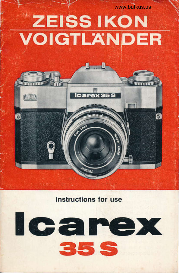
Zeiss Ikon / Voigtlander Icarex 35S User manual
User manual for Zeiss Ikon / Voigtlander Icarex 35S. 19 pages in English. Read the original PDF, download or print a copy without registration.
19 pagesEnglish4.3 MB PDF
Loading your manual…Open PDF directly
Document details
- Brand
- Voigtländer
- Model / document
- Zeiss Ikon / Voigtlander Icarex 35S
- Document type
- User manual
- Language
- English
- Pages
- 19
- File size
- 4.3 MB
- Category
- Film cameras
- Document date
- Not specified in catalog
Search available document text
Find a term, then jump to its page in the original PDF. Image-only pages may not be searchable; check the PDF for exact wording and diagrams.
Page 3 · Read text
www.butkus.us


    Mike Butkus  DigitallyDN:email=mike@butkus.org,Date:cn=Mike2026.01.11signedButkus,by16:52:17Mikeo, ou=Butkus.org,Butkusc=US-05'00'
1234567891011


                          www.butkus.us


                  17 18 19 20
View original page 3Page 5 · Read text
r-
i         Controls


II


'

       1 Lever for delayed-action mechanism
       2 Milled ring for interchange of lenses
        3 Aperture setting ring with aperture scale
       4 Focusing ring
       5 Focusing scale in metres and feet
       e Setting mark for distance and aperture with depth of field scale
        7 Window for setting film speed rating in DIN or ASA
       8 Milled ring for setting film speed rating
       9 Diaphragm button for measuring exposure time and depth of field
              control through the viewf inder
        10 Flash socket for flashbulbs
       11 Flash socket for electronic guns
       12 Film-in-use disc
        13 Setting dot for film-in-use disc
       14 Exposure meter window on camera body
       15 Lever for covering viewfinder eyepiece. Normal position "right"
        16 Accessory shoe
        17 Shutter release with screw-in socket for cable release
       18 Rapid advance lever with exposure meter switch
       19 Shutter speed setting disc with speed scale
       20 Shutter speed setting dot
       21 Rewind button with fold-away rewind crank
       22 Film winding lug (must engage in slot of film cassette shaft)
       23 Film cassette compartment
       24 Release button for rewind locking mechanism
,      25 Viewfinder eyepiece with eyecup
i       26 Tripod socket;,       27 Film counter
             Transport roller with sprocket rings for engaging the perforations ofi           ,t              the film
       29 Take-up spool with slot and tooth for engaging film leader
       30 Milled disc for turning film take-up spool
       31 Eyelets for carrying straps
       32 Battery compartment
       33 Battery cover with inserted battery

          4
.l
View original page 5Page 6 · Read text
Venmo @mike-butkus-camera  Ph. 2083
PayPal Name  Lynn@butkus.org      www.PayPal.me/lynnbutkus
View original page 6
Page 7 · Read text
www.butkus.us
Loading and unloading


lnserting the film
(Do not carry out in direct sunlight!)
Pull rewind knob 21 upwards until the camera back is released. Then slip
the film leader which projects from the cassette into the slot in take-up
spool 29 and engage with one of the perforations to the tooth in the slot.
 (lf the slot is not visible, rotate the spool by turning milled ring 30.)
Next pull the cassette across the film track and drop into film compart-
ment 23, rewind knob 21 again being pulled upwards as far as it will go.
Now push the rewind knob right down into the camera.
Rotate the take-up spool by turning milled ring 30 until the perforations
at both edges of the film are engaged by the sprockets of transport
roller 28.
Lift up the eyecup, close the camera back and press down until an
audible click indicates that it is firmly closed. Now operate rapid
advance lever 18 and release button 17 until the number "1" appears
below the red index in film counter27. As soon as a number is visible in the
film counter window, this indicates that there is a film in the camera
(loading control). When the film counter moves on, the film has been
advanced (film transport control). The film counter always indicates the
number of frames that have already been exposed.


Setting the lilm speed
Set the speed rating on the camera immediately the lilm has been
inserted or check the speed that is already set. The film speed rating
in DIN or ASA is given either on the film packing or in the instructions

                                                                            5
View original page 7Page 8 · Read text
www.butkus.us
for use. Turn milled ring 8 until the appropriate number is opposite the
red triangle below window 7.
 lf the number given is not engraved on the scale, set at a suitable
intermediate rating.


Film-in-use disc
This serves merely as a memory aid and does not iniluence the camera
action.
When disc 12 is turned the symbols click into position above setting
dot 13. They present:


                  colour reversal film for daylight exposures

                   black-and-white film

                    colour negative film

                    colour reversal film for flash exposures

                      infra-red film

                  colour reversal film for artificial light.
View original page 8Page 9 · Read text
www.butkus.us
Removing the tilm
Alter exposing the last frame (the film counter indicates the number
corresponding to the number of frames on the film), do not advance
lever 18 but rewind the film. Press down button 24 to release the rewind
locking mechanism and turn rewind crank 21 clockwise until the iilm
counter indicates the initial position and a slight resistance  is felt. Only
now open the camera back by pulling up the rewind knob and remove the
tilm cassette. Always keep the take-up spool and tilm guide track clean!


Focusing
Look through the viewfinder and turn setting ring 4 until the split-images
visible in the cenlre of the viewfinder are exactly aligned or,  if the subject
has no distinct lines, use the ground class screen to focus the picture.
The focused distance is indicated on scale 5 at setting mark 6.
lf the viewfinder is blocked out, move the small lever 15 to the right
over the red dot.
lf the viewfinder image is darkened, open the lens diaphragm by de-
pressing button 9. The pre-set aperture is retained.


focusing with split-image indicator      focusing with ground glass screen
View original page 9
Page 10 · Read text
+              +
                               10
                          3
           t              t


Aperlure and depth of field
Pre-set the aperture by turning milled ring 3. The f/number required must
be opposite setting mark 6. The aperture depends on the depth of field
dictated by the type of subject. The smaller the f/number the larger the
lens aperture and the smaller the depth of field. The depth of field
indicated by the pre-set aperture can be read direct from the depth oJ
field scale 6 on the lens.
It covers the range from the distance indicated opposite the f/number
on the left to the distance opposite the same f/number on the right.
The depth of field can also be checked on the ground glass screen in the
viewfinder. By pressing down button 9 the diaphragm is closed to the
pre-set value and thus the aperture or distance can be adjusted exactly
as required. When button 9 is pressed down again, the diaphragm
returns to full lens aperture.  lt is automatically closed down to the pre-set
aperture when the shutter is released. Focusing is also possible with
the depth of field scale (recommended  for snapshots). Determine the
depth of field required with the aid of scale 6 and set the indicated
f/number opposite setting mark 6 by turning ring 3.
Exact data are given in the enclosed booklet containing the depth of
field tables.


Setting the shutter speed
Turn disc 19 until the shutter speed required for the exposure clicks
into position opposite setting dot 20. lntermediate speeds must not be
used.
The shutter speed depends on the lighting conditions and the rate
at which the subject is moving. The faster the movemenl, the shorter the
exposure time. The numbers on ring 20 denote fractions of a second
(60 =  t/ro sec.). The orange numbers indicate that a tripod should be
used.

8
View original page 10Page 11 · Read text
www.butkus.us
When set at "B", the shutter remains open as long as the release
button is depressed.
Shutter speed and aperture are inter-dependent. The fasier the shutter
speed, the larger the aperture and vice-versa. The exact values can be
determined with the built-in exposure meter.


Exposure measurement
To switch on the exposure meter, lever 18 must be swung out and dia-
phragm button 9 depressed. Now pre-select shutter speeds.
Sight the subject with the camera held in a horizontal position, even
if the exposure is to be made with the camera in the vertical holding
position. Turn aperture ring 3 until the exposure meter needle in the
viewfinder or on the camera body below window 14 is positioned exactly
in the centre of the triangle.
The aperture is indicated at the top of the viewfinder. lf a definite aperture
is dictated by the type of subject, pre-select this aperture and turn shutter
speed disc 19 until the exposure meter needle coincides with the centre
of the triangle. Only a click-in shutter speed must be used, otherwise
adjust the aperture setting.
 lf the indicator below window 14 is used for exposure measurement, for
instance, when using a tripod, the viewfinder eyepiece must be covered,
in order to keep disturbing stray light from entering and falling on the
photo-resistor. To do this, move lever 15 to the left (red dot becomes
visible).


              indicating aperture

        Exposure meter needle

                  setting triangle.
View original page 11Page 12 · Read text
The exposure meter
 Light metering is through the lens (inside metering). The tight fatts on
two CdS photo-resistors. These regulate the battery power in relation to
the incident light. The exposure meter in the lcarex 35 S has standard
calibration. lt provides correct exposure for average conditions.
Correction  is necessary:
Against-the-light exposures, dark subjects against a bright background
                            (overcastor   subjects             of low contrast                                              landscapes)                                                             -                                     sky -1/zsnow     measurementafter                             aperture               open the                                                stop. Subjects                                      lo 1                                                        of high
contrast,            in particular,                      very                               bright                                  subjects                                           against                                                 dark backgrounds -after measurement                   close                         the                             aperture                                                          t/z to                                          1 stop.


Battery
The "Mallory PX 13" provided in the camera to operate the exposure
meter will last about one year under normal use. Ax extremely low
temperatures below -10o C, use type "Mallory PX 625".
When testing in the open at average brightness with the camera set at
r/eo sec., the battery is still in working order as long as the exposure
meter needle moves across the entire acceptance field on turning the
aperture ring after the diaphragm button has been depressed and the
rapid lever swung out. lf this is not the case, the battery must be changed.
It is accomodated underneath cover 33 which is removed by turning to
the left. When inserting a new battery take care that it is poled to match
the signs on the cover. New batteries are obtainable from photographic
dealers.
The exposure meter should be switched off when the camera is not in
use for longer periods.  li is switched off when the diaphragm button
projects or the rapid advance lever is pushed in.


The exposure
When taking a shot press down release,button 17 rapidly and smoothly.
The mirror swings up, the diaphragm closes down to the pre-set lens
aperture and the focal-plane shutter travels at the pre-set speed.
lmmediately afterwards, the mirror returns to its position for viewfinder
focusing. When the diaphragm button in depressed, however, the dia-
phragm always remains at the pre-set aperture after release and
tensioning.

10
View original page 12Page 13 · Read text
www.butkus.us
Working with depressed diaphragm button is particularly recommended
when variable lighting necessitates frequent adjustment of the exposure
meter.
When the shutter has been released, a red warning index appears in
the bottom left-hand corner of the finder as an indication that the
shutter must be tensioned before the next exposure. To do this, swing
lever 18 through until it stops.


Self-timer
Tension the shutter beforehand with the rapid advance lever and then
press lever 1 upwards as far as it will go. On letting go the lever about
8 seconds elapse before automatic exposure. During this time the lever
returns to its initial position.
Time exposures (shutter setting "8") are not possible with the delayed-
action mechanism.


Filters
The yellow, green, orange and red filters that are available for the
ICAREX can be used only with black-and-white film, whereas the UV,
lkolor B, skylight and CONTAPOL filters can also be used with colour
material. These filters in bayonet mount fitting B 50 fit all ICAREX lenses
from 35-135 mm.
The through-the-lens light metering system means that the filter factor
is usually adjusted automatically. Only when using the more dense colour
filters for black-and-white  films is it available after exposure measure-
ment to open the aperture one stop or increase the exposure time by
one full value (corresponding to filter factor 2 x).


Flash exposures
When the flash symbol on slide 19 is set at index 20 contact-making is
so controlled that the different flashbulbs and electronic guns are fired
at the correct moment. Contact for firing the flashbulbs (e. 9., type AG)
is made at socket 10 (flashbulb symbol), for electronic guns at socket 11
flash symbol). The flash equipment itself can be either slid onto acces-
sory shoe 16 orfixed on a rail in tripod socket 26.
Connection to the camera is by means of an adapter available from
photographic dealers; the cable is connected to one of the two flash
sockets.

                                                                                          11
View original page 13Page 14 · Read text
The aperture setting can be taken from the tables given on the flash-
bulb packing. For electronic flash, use the aperture calculating discs
on the gun. The instructions given by the flash equipment manufacturer
musi be followed.


Lens exchange


                                             www.butkus.us
View original page 14Page 15 · Read text
www.butkus.us
 Note!
When removing or attaching the lens rotate only milled ring 2, in order
to avoid any possible damage to the mechanism for closing the dia-
phragm. This also applies when taking the lens from or placing  it back
on the red base plate in the case.
Removing the lens: Rotate milled ring 2 anti-clockwise until it stops and
 lift out the lens.
Attacfiing the lens: First line up the red dot on the inside of milled ring 2
with the red dot on the lens. (The ring clicks into this position.) Then
insert the lens so that the red dots on the lens and the camera body
are exactly opposite each other. When the lens is actually touching the
camera body, turn milled ring 2 clockwise to lock the lens in position.


Exposures with tele attachment 8 x 30 B
When using tele attachment  I x 30 B the lens is stopped down to an
invariable smaller aperture. During exposure measurement the aperture
ring must be turned to provide full aperture. Actual measurement is made
by turning speed ring 19.


Glose-ups
Besides the focusing ranges of the lenses, close-ups up to an image
scale of 3:1 are possible with supplementary lenses, extension tubes
and a bellows unit. The tables booklet contains not only all the necessary
iables but also a diagram showing the exposure ranges thal are available
in this way. Since the reduced depth of field in close-ups requires
additional stopping down, which in most cases results in longer ex-
posure times, the use of a tripod and cable release are recommended.
Reference is made here to our table copying unit and our universal
copying unit REPROPHOT. The latter unit is equipped with a focusing
slide which is practically indispensable for close-ups.


Exposure measurement for close-ups
ll supplementary lenses, extension tubes 1:2 and 1:1, the bellows
focusing unit or microattachment are used, exposure measurement  is
in principle the same as described above.
The exposure factors given in the tables booklet for extension tubes
and the bellows unit do not refer to the ICAREX 35 S. They apply only
to lcarex models without an exposure meter.

                                                                           13
View original page 15Page 16 · Read text
Supplementary lenses
The bayonet fitting rD e SO fits all ICAREX lenses from 35-135 mm in the
same ways as filters. ln order to obtain a sufficient depth of field, however,
the lens should be stopped down to at least f/5.6.  lf filters are also used,
these are to be mounted in front of the supplementary lenses.


                     www.butkus.us
View original page 16Page 17 · Read text
www.butkus.us
Extension tubes
The two extension tubes extend the focusing range of the ICAREX up
to an image scale of 1:2 and 1:1 (particular advantage when copying
slides). The image scales 1:2 and 1:1 apply, however, only to exposures
taken with 50 mm lenses. These values are not correct, if referred to
any other lenses.
The tubes are attached to the camera as described under lens exchange.
ln the same way, the lenses are then attached to the front bayonet
mount fitting of the tubes.
Diaphragm pre-setting or depth of field control by depressing button 9
is not impaired by the extension tubes.


Bellows focusing unit
As shown in the diagram of image scales, a magnification of approximately
5 times can be achieved on the negative with the bellows focusing unit
and the 50 mm lenses. The 35 mm lens cannot be used with the bellows
unit, because the lens would lie within the range of the rails. The bellows
focusing unit is first attached to the camera and then the lens to the
bellows unit with the bayonet rings over the dot markings.
The bellows are extended by turning the right-hand knob on the focusing
slide. When turned clockwise, the left-hand knob serves to lock the
setting. Focusing is also possible with the focusing mount on the lens.
On the left-hand rail is a millimeter scale which can be used to re-set
extensions, even when other exposures have been made in the mean-
time. A swivel arm permits exposures with the camera both in vertical and
horizontal positions, whereby the camera engages in extreme positions.
Diaphragm pre-setting  is not possible with the bellows focusing unit.
lf a correction in the focusing is necessary after exposure measurement,
the diaphragm must be opened manually and then re-closed manually to
the pre-selected f/number before exposure.


Microphotography
For exposure measurement in microphotography set speed ring 19 at
the slowest speed (t/z sec) and then adjust the brightness of the
microscopic lamp so that the needle in the viewfinder coincides with
the centre ol the triangle marking.
When very bright subjects are involved, adjustment is possible by
reducing the exposure time.

                                                                           15
View original page 17Page 18 · Read text
Accessories


               Intercfiangeable lenses for ICAREX 35 S
11.2003       Skoparex 3.4135
11.2001        Color-Pantar 2.8/50
f .2042       Tessar 2.8150
11.2014        Ultron 1.8/50
11.2004       Dynarex 3.4150
11.2005       Super-Dynarex 4113s
20.1629       ZEISS tele attachment 8 x 30 B (f = 400 mm)
20.1644       Adapter ring for 20.1629
11.2008       Super-Dynarex 41200               I
11.2010       Telomar 5/400                      [ with case11.2012       Zoomar 2.8136-82 Vario lens  )

               Viewfinder Accessories
20.16',14       Angle telescope
20.0504       Eyepiece correction * 0.s to + 5 dptr.

              Lens hoods
20.07't8       Lens hood (pull-out type) for 35 to 90 mm lens S. 56 O
             Lens hood available for Super Dynarex 135, 200 and
             Telomar 400
20.5752       Lens hood forZoomar S.95 0

                  Filters
20.1051      yellow lor 35 to 135 mm lens B 50 O
20:.1052     green  for 35 to 135 mm lens B 50 0
20.1053      orange for 35 to 135 mm lens B 50 @
20.1054     red      for 35 to 135 mm lens B 50 @
20.1055    UV      for 35 to 135 mm tens B 50 0
20.1058        Skylight for 35 to 135 mm lens B 50 @
20.1056         lkolor A for 35 to 135 mm lens B 50 0
20.1057         lkolor B for 35 to 135 mm lens B 50 0
20.6041      yellow S 77 0l
                                                    4120020.6045    UV    577 Q I tor Super-Dynarex
20.6048        Skylisht 577 A)
20.6051             s^11@^                 I:Ll-"y             I tor, Telomar and zoomar (for zoomar20.6053       oranoes9S(i9)-   onlv with adapter 20.6605)20.6055      Uft?;"           |
20.1208        Polarizing filter (Contapol) for 35 to 135 mm lens B 50 0

16
View original page 18Page 19 · Read text
7T
                                         www.butkus.us
                  Accessories for close-ups and photomicrography
     20.0846       Supplementary lens t = 2.0 m 0.5 dptr. B 50 0
     20.0847       Supplementary lens f = 1.0 m 1.0 dptr. B 50 @
  r 20.0848       Supplementary lens f = 0.5 m 2.0 dptr. B 50 0
     20.0849       Supplementary lens f = 0.3 m 3.0 dptr. B 50 @
     20.0850       Supplementary lens f = 0.2 m 5.0 dptr. B 50 @
     20.1640        Extension tube 1:1 for 35 to 135 mm lens
     20.1647        Extension tube 1:2 for 35 to 135 mm lens
     20.1630        Bellows focusing unit for 50 to 135 mm lens
     20.1646       Extension tube for microscope
     20.1616       Connecting head for microscope
     20.1853      REPROPHOT universal copying unit
     20.1850       Table copying unit
  r  20.1852        Lighting equipment for table copying unit
     20.0205       Adapter plate for connection of ICAREX 35 S to copying
                    units

                Gases and containers
     23.0016        Ever-ready case, standard type
     23.0013        Ever-ready case, de-luxe type
     23.0207        Universal case
     23.0211        Carrying straps (real leather) with spring rings
                     for camera without case
     23.1004        Leather case for 35, 50 and 90 mm lens (optional)
                and 1 filter or 1 supplementary lens
     23.1203      Case for 3 filters or 3 supplementary lenses
     23.2007        Leather case for ZEISS tele attachment 8 x 30 B
               The lcarex system is going to be extended still further.


                                                                               17
View original page 19Related documents and language editions


From the M. Butkus archive. Original publisher and archive notices are retained.
Check the model and edition against your equipment.
PDF verified 2026-10-10.