Film cameras
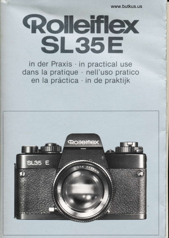
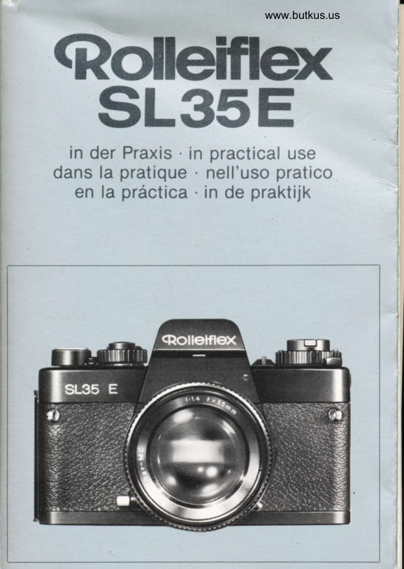
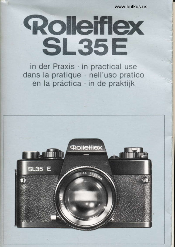
Rolleiflex SL 35 E User manual
User manual for Rolleiflex SL 35 E. 26 pages in English. Read the original PDF, download or print a copy without registration.
26 pagesEnglish4.2 MB PDF
Loading your manual…Open PDF directly
Document details
- Brand
- Rollei
- Model / document
- Rolleiflex SL 35 E
- Document type
- User manual
- Language
- English
- Pages
- 26
- File size
- 4.2 MB
- Category
- Film cameras
- Document date
- Not specified in catalog
Search available document text
Find a term, then jump to its page in the original PDF. Image-only pages may not be searchable; check the PDF for exact wording and diagrams.
Page 1 · Read text
www.butkus.us
 SL35E
                                                                 .  in der Praxis  in practical use
                          .dans la pratique                   nell'uso pratico
  en la prdctica  . in de praktijk
View original page 1Page 2 · Read text
b''                                                      '               Pagina Inhalt                          Seite   Indice
Einzelteileund Funktionen .....   2   Pahiefunzioni           ... Al
VordererstenAufnahme  ......   4    Prima di cominciare a fotografare 66
Vor jeder Aufnahme           I    Prima di ogni fotografia.  . . . . . . . 70
Achtung - Aufnahme! ........13    Attenzione:scatto! .....  76Nach jederAufnahme ...14   Dopoloscatto         ...77
Nach der letzten Aufnahme.  . . . . 15    Dopo f'uftimafotografia.  . . . . . . . 77
TipsfUrdiePraxis  ......  15   Consiglipratici       . .. .. .. . 78Daten und Zahlen        . . . .... 20   Datitecnici          ......84
Bitte beim Lesen'die erste und letzte    Durante la lettura, tenete aperti  i due
Umschlagseite herausklappen.              risvolti di copertina.


Gontents                  Page    lndlcc                     PAgina
Gontrolsand components.   . ..  . . 22
Before taking your first picture . . 24
Beforeeachexposure  ...  . ..... 28
Shooting          ........33
Aftereachexposure. .... 34
Afterthelastexposure   .. .. ...  . 35
Practicalhints .        ...:....  35
Factsandfigures .......  40
When reading, please open the first    Sirvase abrir la primera y la 0ltima
and the last cover leaf.                 pdgina.


Gontcnu                  Page   lnhoud                    Bladziide
El6mentsetfonctions  ... 42    Onderdelen en funkties .......  112Avant la premidre photographie . 44    Voordat U gaat fotograferen   . .. 114
Avantchaquephoto ..... 48  Vooriedereopname. ... 118
                                                                123Attention - prisedevues!  .....  54   En nu...deopname! .....  ...Aprds chaque prise de vues ,. . . . 54  Naiedereopname .....  124
Aprds la dernidre prise de vues . . 55   Na de laatste opname       . . 125                JConseils pour la pratique.  . . . . . . 56    Tips voor de praktijk           . . . 125
Caract6ristiques techniques  . . . . 61   Technischegegevens  ..130                                                                                                                                   .s#{'q
D6plier la premidre est la derniere      Bij het lezen de eerste en de laatste
page de couverture,  s'il vous plait.      zijden van het omslag uitvouwen.                           :#
                                                                                                                     :lffi
View original page 2Page 3 · Read text
www.butkus.us


Mike Butkus   DigitallyDN:email=mike@butkus.org,Date:cn=Mike2025.02.07signedButkus,by16:13:37Mikeo, ou=Butkus.org,Butkusc=US-05'00'
View original page 3
Page 5 · Read text
www.butkus.us
Gontrols and components
 1 Camera back locating Pin
 2  Film pressure plate
 3 Camera back, with film tab holder
 4  Eye cup, also eyepiece mask
 5  Hot shoe with flash centre contact
 6  Battery check mark (BC = battery check) 7  Battery check button (green)
 8  Rewind knob
 9  Cover disc for continuous exposure correction
10 Rewind crank, folding
11 ASA/DlN setting window
12 ASAJDIN setting lock
13 ASAJDIN setting index
14 Self-timer setting lever
15 Self-timer lock index
16 Red LED signal for self-timer and battery check
17 Aperture scale port
18 Red dot on camera bayonet
19 Camera bayonet
20 Deoth of field scale
21 Aperture and distance index
22 Infrared index (red)
23 Interchangeablelens
24 Aperture ring
25 Camera diaphragm plunger
26 Instant return mirror
27 Stopdown pin for checking depth of field and working aperture measure-
    ment
28 Shutter speed lock
29 Right-hand neck strap lug
30 Camera back bottom hinge
31 Frame counter window32 Shutter release lock index (red)
33 Shutter release lock
U  Camera back top hinge
35 Cable release socket
36 Shutter speed dial (fast exposures = white, slow exposures and B -
     orange, X for flash exposures = yellow, A for automatic exposures =
37 Shutterred)     release formed as combination button for battery switching,
     metering (first pressure), meter reading memory (second pressure) and
     releasing
38 Shutter speed dial index


22
View original page 5Page 6 · Read text
>
        39  Compartment for film cassette
I,       40   Film spool engagement lug
        41   Eyepiece mount, also location for eyepiece accessories
       42   Interchangeable eyepiece lens
       43   Lever for film rewind (R)or for multiple exposure (M)
       44   Film advance and shutter cocking lever
       45   Film transport sprocket
       46   Film holding clip (white)
       47  Knurled flange for film loading
       48   Drive cam for motor winder
       49  Camera base with camera number, origin and marking
           (B = battery, MD - motor drive)
       50   Fitting hole for motor winder
        51   Oscillating  leaf focal plane shutter
       52   Battery compartment
       53  Tripod bush 1/4"
       54  Motor coupling cover (MD)
       55  Locking button of bayonet mount (red)
       56   Battery compartment cover (B)
       57  Lens diaphragm plunger
       58  Distance scale in meters (white) and feet {green)
       59  Lens bayonet
       60  Focusing ring
        61  Red dot on lens bayonet
       62  Lug for aperture simulator
       63  Signal contacts for motor winder
       64   Left-hand neck strap lug
       65  X flash cable terminal
       66   Film speed setting disc in ASA (orange)and DIN (white)


                                                                             23
View original page 6Page 7 · Read text
Venmo @mike-butkus-camera  Ph. 2083
PayPal Name  Lynn@butkus.org      www.PayPal.me/lynnbutkus
View original page 7
Page 8 · Read text
www.butkus.us


            cD
Belore taking your first picture
Make a nole of the serial numbers
Camera bodies and lenses have serial numbers which should be noted and
kept in a safe place. These numbers will help you in recovery or proof of
ownership in case of loss.

Insert baltery
Undo cover 56 by turning anla{lockwise wilh a coin. Rub batteries on both
sides with a cloth to remove any oxidation. Insert battery in battery compart-
ment 52 with the plus sign facing outwards (corresponding to the plus sign in
the cover)-fig. C. Do not touch the battery poles when doing so. Screw
cover an position again and tighten gently (in an emergency cover 54 will also
fit).
You should use new 6 V silver oxide batteries such as lMalory PX'28, Varta
V 28 PX or equivalent makes of other manufaclurers.

Check battery voltage
Depress lock button 28 and engage shutter speed dial 36 at A or set between
1/1000 and 16 sec.
Depress button 7 for about 2 sec. diode 16 illuminating red during this period
indicates sufficient battery voltage fig. D.


24
View original page 8Page 9 · Read text
www.butkus.us

                                                       E
lmportant: Begularly (l)repeat this voltage check; exchange battery immedia-
tely. af diode 16 fails to light up for 2 sec. Batlery life is 1 - 2 years, bul repla-cement every year is recommended. lf out of use for any considerable periods
keep the battery in a safe place away from the camera. Remove spent batlery
immediately. After prolonged periods out of use clean and check battery as
described above.
Fitting lhe lens
Depress red locking button 55, release cap 67 from camera bayonet 19 by tur
ning anticlockwise-fig.  E. Pull front and rear caps oll the lens (the former
by depressing the two catches). Fit lens 23 so that the red dct 61 on the lens
bayonet is opposite red dot 18 on the camera bayonet, then lock by turning
clockwise to fullest extent.

Changing the lens

Here as well depress the red locking button 55 and release the lens as shown
in fig. E. The "quick bayonet mount" of lhe lenses permits particularly fasl
single-handed changing: the right hand uniocks bulton 55 with the index fin-
ger and at the same time releases the lens. When  f itting the interchangeable
lens both red dots must be in alignment.
lmporlant: As far as possible change the lens in the shadow of your body,
avoid bright sunlight and dust. When changing the lens do not touch instant
return mirror 26. When no lens is fittecl insert cap 67 into camera body. Fit
front and rear caps on interchangeable lcnses when not in use.


                                                                       25
View original page 9Page 10 · Read text
www.butkus.us


                                                        F

Loading lhe film
Depress shutter speed lock 28 and engage shutter speed dial 36 at X (slow
speeds would make film advance dilficult for the first exposure). Release ca'
mera back 3 by pullinq rewrnd knob 8 and open-fig.  F. Pull cut rewind knob
to its fullest erierif aiO load film cassette. Turn rewind knob until it can be
pushed in again. Turn knurled flange 47 until one of the white film holding
clios 46 is on top. Pull film leader out of cassette and engage in the top hol'
ding clip.
Turn knurled flange in directaon of arrow in order to secure the film ieader,
move shutler release lock 33 right over to the left. Move lever 44 over to its
fullest extent and allow to spring back. then fully depress shutter release 37
Repeat this process unlil lhe film perforations engage on both sides of
sprocket 45. Close lhe camera back and ensure that the catch engages.
Window 3.1 now indicales that the lilm is loaded.but cannot yet be used: :  S
(Start). Continue to operate the shutter release and cocking lever alternately
until the ligure "1 " appears under the index.
Check for correct film advance: the frame counter will only count  if the film is
correctly loaded and advanced! The rewind knob 8 will also rotate as the film
is advanced (with 20 and 12 exposure cassetles or short lengths of bulk film
possibly only after several exposures). For lhis reason do not hold the rewind
knob while operating the lever 44.
To mark the film type used, tear off the tab of the film box and push into the
film tab holder at the camera back 3.


26
View original page 10Page 11 · Read text
G                          H
Setling the lilm speed
Set cover disc 9 with window   l 1 to the speed of the film loaded. Depress lock
12 and allow selting disc 66 to engage with the previously set value against
index 13-fig. G.
The DIN ratings are in white and the ASA ratings in orange. the dots and trian-
gles represent DIN and ASA intermediate values. The range of adjustment  is
from 15 to 39 DIN and lrom 25 to 6400 ASA.
Note: Constant exposure correction (for example effective for all exposures
on a film) can be obtained by turning setting disc and cover disc -Hint  2.
Locking the shutter release
Engage release lock 33 -fig. F against red index 32. Shulter release 37 is
now locked, thus preventing inadvertent swilch-on the electronic syslem.
N4ove setting lever 14 lo index 15 to prevent unintentional self-timer exposures
as weil.

Filting lhe eye cup
As shown in fig. H. push eye cup 4 to its fullest extent onto eyepiece mount 41
from above. In this position the viewfinder window is open and screened from
extraneous light when shooting: at the same time the camera back is also
locked to prevent unintentional opening. Eyepiece 42 as closed by pushing the
eye cup upwards (e.g. for long time exposures without constantly checking
the viewfinder image'-Hint  5).


                                                                             27
View original page 11Page 12 · Read text
www.butkus.us


                                                            J
TheevecuocanIfnecessarybefo|dedbackagainsttheeyepiece.Inler-
chanobaole eyepieces from + 4 lo -4 dioptres are available as an accessoryto colrect eyesight defects
Fitling lhe neck strap
Pull neck strap 68 as shown in fig. J with the seam facing inwards through the
io-op. on tn" non'slip attachment"and  then through the rings of lugs 29 and 64'
S-e-Jure enOs at required length. Move non-slip tttachment to center of neck
strap Iength.
Bcforo oach orpoauro
Unlock shutter release
Move lock 33 right over to the left and engage
 Holding lhe camera coneclly
 is made practically automatic by virtue of the functional shape and logical
 arrangement  of the camera controls:
 For horizontal format Pictures                                                                   release                                           on shulter                                             37-                                                   flnger                                       index gotO                              righl                  with the         camera      ine                          hand -                                                                 and                                                           range                                                     sets the                                    and also                                       lens                                 the                          round                        is held     X.               left hand t,o.      fne
 iJ"rture. keep tne eye close to eye cup 4, thus firmly supporting the camera
 on your forehead.


 28
View original page 12Page 13 · Read text
www.butkus.us

                                                            J
The eye cup can if necessary be lolded back against the eyepiece. Inter-
changeable           eyepieces                   from + 4 to -4 dioptres are available as an accessoryto correct eyesight                    defects.
 Fitling the neck strap

Pull neck strap 68 as shown in fig. J with the seam facing inwards through the
loops on the non-slip attachment and then through the rings of lugs 29 and 64.
Secure ends at required length. Move non-slip attachmenl to center of neck
strap length.
Botoro each oxporur€

Unlock shutler release
Move lock 33 right over to the left and engage.
Holding the camera coneclly
is made practically automatic by virtue of the functional shape and logical
arrangement of the camera conlrols:
For horizontal format pictures
Hold the camera with the right hand -  index finger on shulter release 37-fig. K. The left hand is held round the lens and also sets the range and
aperture. Keep the eye close to eye cup 4, thus firmly supporting the camera
on your forehead.


28
View original page 13Page 14 · Read text
www.butkus.us


For verlical format oictures
Turn the camera round through 90' as shown with lhe same grip This position
allows the fastest changeover from vertical to horizontal format, but according
to requirements other iamera positions are possible or more practical, for
examble holding the camera above your head in a crowd or held down with
your arm outslrelched  for unobserved snapshots.
S€lecting piclure area and locusing
These operations are usually carried oul simultaneously in practice' the
picture area or the depth of field predominating according to the subJect'
Point camera at subject, hold camera straight and wilhout lilling When
looking centrally into ihe viewfinder eyepiece  all four corners of the viewfinder
image should (with normal eyesight) be fully visible.
Align split-image rangelinder 70 or microprism spot 71 or ground glass screen
72"witir the mdst imdortant section of the picture area. Turn locusing ring 60
until the picture section appearing distorted in the rangefinder is straightened,
or the unsharp or flickering image is sharply defined-fig  -.
According to subject and exposure conditions the focusing aids should be
used as iollows: rangefinder 70 (diagonal distorted partial image) for rapid
focusing on subjects with distinct oullines;
microprism spot 71 (sharp definition, clear transition from sharp to unsharp)
for spbrting evenls, reportage and snap shots as well as for spacious subjects
with gradual lransition;


                                                                       29
View original page 14Page 15 · Read text
ground glass screen 72 for general focusing of important off,center sections
of the picture. and for close,ups. macro. micro and copying work where sharp-
ness is checked right up to the edge of the frame (uniforrnly bright illumi,
nation from the center to the edge by virtue of super-fine Fresnel lens
structure).
Selecling lhe aperlure
Turn aperture rrng 24 and set requtred aperture against Index 21 ->fig  tvl. The
setting ring has clrck stops for each aperture. but any intermediate positions
can also be used. The aperture set is reflected directly from the lens and ts
visible in window 74 >fig. L underneath the vtewfinder image.'
Typical values for aperture setttngs according to brightness. film speed and
s u olecl:
f111-22 in bright daylight in summer. for seasjde and mountain shots or for
high and extra-high speed 200-6400 ASA fitms, 118.22 lor increased depth of
f ield. f/2.8-5.6 for shulter speeds with rapid movernent:  f/1.4-2.8 for low depth of
field: f/4-8 for slow to medium speed 25,160 ASA films; f/1.4-4 for dim lighting.
interior shots. mist and rain.

                                                                  ' only wrth oflgrnai lenses fttted dtrectiy
30                                       Into the camera t'ayonet
View original page 15Page 16 · Read text
www.butkus.us


                                                   1
                                  2


                   M


                                                   N
Exposure metering with LED automatic control
Alter selecting the aperture, move cocking lever 44 to ready position-fig.  M.
Depress shutter speed lock 28 and engage dial 36 in A = automatic position.
Unlock shulter release 37 with lever 33. Point camera at sublect and align
center of viewfinder with center of interest. First of all only take up the tirst
prcssure on the shutter release >fig. N.
The shutter speed now measured will be indicated in the viewfinder by a red
LED' signal on scale 73:
one LED lighting up - indication of shutter speed directly opposite, in case of
rntermediate speeds two adjacent LED s rlluminate        O.A// LED'S in row /5 lighting up sjmultaneously (or LED-fig.indication below 1/1000
sec at plus) ,-f iq. P = warning signal - measured exposure time is outside
range of camerai the pre-selected aperture must be corrected with ring 24:
larger aperture with dirn light. smaller aperture with very bright Iight.
All LED s lighting up as shown in tig. P may. however. also Indicate an unsut'
 f icient battery voltage            24.
              -paEeExposure metering wilh LED tollow.up system

With pre-selected shutter speed
Depress lock 28 and set dial 36 wrth requrred shutter speed to index 38. Fast
speeds trom 1/1 000 to 1/60 sec are white. slow speeds    f rom 1/30 to 16 sec are

 LED = Lrght Ernrttrrrg Diode                                                        l1
View original page 16Page 17 · Read text
orange. Settings trom                         l/1000 lo 'l12 sec are shown as fractions of a second,                          .16settings from 1 to   sec in whole seconds. The setting dial does not have
click stop engagement  at these speeds.
With ore-selecled aoerture
Select the required aperture as descnbed with ring 24; the f-number  is
displayed undernealh the viewfinder image.
Point cam€ra at subject and take up the lirst pressure on the shutter release,
lhen note viewfinder displays: shutter speed setting is indicated by continu.
ous illumination of the adjacent LED'S-fig. O.
lf, in addition, as a warning signal another shutter speed or the plus symbol or
   wholethe                          starts                                to flash         row of LED's
correct       exposure:                          aperture               change                                  and/or-f  igs.shutterQ andspeedR, thereuntilis a thisdangerflashingof in-
stops.

The interval between continuous light and flashing signal of one or two LED'S
(between 16 and 1/1000 sec) also indicates the difference between the selec-
ted and the measured shulter speed-fig.  Q; thus, for example,  it is possible
to obtain intentional over- or underexposure. Here, a change of one shutler
speed or f-number corresponds in each case to hall or doublethe exposure.


32
View original page 17
Page 18 · Read text
www.butkus.us


             ST
Open aperlure or working aperture measuremenl
Exposure is measured with original lenses fitted directly into the camera
bayonet at "open aperture". i.e. without depressing the stop-down pin (lhese
lenses have an aperture simulator as can be seen by lug 62).
When usrng lenses without aperture simulator  (e.9. lenses for SL 35, M 42
leases with adapter, lenses of olher makes) or when using extension tubes,
bellows and adapters, measuremenl should be carried out at "working
aperture :depress stop-down pin 27 until it engages+fig.  S. Simultaneous
illumanation or tlashing ol all LED's (with otherwise correct setting) indicates
incorrecl setting of the stop-down pin if lens withoul aperture simulator or no
lens inserted at ali. Working aperture measurement is also possible with ori-
ginal lenses. either with or without automatic conlrol.
Shooting
Hold camera firm and steady,  if possible with support and ensure a lirm
slance - then fully depress shuller release 37 past lirst ptessure and past
second pressure -  the picture will be ideally exposed al the shutter speedindicated by conlinuous  illumination.

Using cable release
With long exposures. as lrom about 1/30 sec screw cable release into socket
35 and use tripod or firm camera support. Time exposures+Hint  5.


                                                                       33
View original page 18Page 19 · Read text
Using the self-timer
Set lever 14 to index-+tig.T.  Fully depress shutter release slowly and gra-
dually, the red diode 16 lights up. When the button is released the delay
time of 10 sec starts to run; the red diode 16 extinguishes when exposure
commences.
To interrupt the self-timer: during the delay time depress the shutter release
 again aniJ keep it depressed. Restart delay time by letting go the shutter
release.
To switch off the self-timer before the delay time starts to run: move setting
lever to 0.
To switch off the self-timer during the delay time:depress the shutter release
again and keep  it depressed. Reset lever 14 to 0, whereby releasing  will follow
immediately.

Multiple exposures
Make the first exposure as usual, then put lever 44 into rastposition -->tig.U.
Set lever 43 to "M", move lever 44 to its fullest extent and back again. Fully
depress shutter release: the first film frame will thus be exposed a seconcl
time. For every further multiple exposure required, repeat the whole procedu-
 re. Lever 43 resets automatically when releasing the shutter. Manual resetting
 can also be done by touching gently the release until its first pressure point.

After each erposuro
Let go the shutter release and (after the shutter action) fully cock lever 44 and
allow to spring back -->fig. M. When shooting in rapid sequence keep the
camera held up to your eye. The cocking lever can be actuated in a single ope'
ration or in stages and when not in use should be returned to the stop. Before
longer intervals between shooting secure shutter release with lock 33.
The frame counter 3'1 indicates how many exposures have been taken on the
film loaded. The 2$th and 36th exposure (corresponding to 20 and 36 exposure
films)are marked in orange, the intermediate readings being indicated by stro-
kes. After the 36th exposure, according to film length and whether the leader
has been fully used up, it is sometimes possible to expose further frames.
When these additional frames are used the"='r will appear in the window (do
not use force as this may cause scratching or even tearing of the film).
Note: the frame counter only works with loaded and advanced film and with
the camera back closed; when the shutter is next cocked  it springs back to
"s".


u
View original page 19
Page 20 · Read text
www.butkus.us


                                                   U
 After the last erpoaure

Secure shutter release. engage lock 33 against red index. Set rewtnd lever 43
to R  .fig. U. Unfold rewtnd crank 10 and turn in direction of arrow until the
resrstance from the film tension ceases. When rewinding the ftlm the frame
counter also runs back and finally stcps at S (rewind check) -  the film leader remainS oulslde the cassette.  lf the fiim rs wound back further the S'
 will continue to appear -  the filnl leader rs /ns/de the cassette. Push up or re.
move eye cup. pull up crank 10. Fully open the camera back 3 afler  it springs
open. oull rewrnd knob out to rts lullest extent and remove the cassette.
ihe film should tre removed at least in the shadow of /our body. brieht sun.
lrght and ciust shoutd be avoided.


Practical hints
   Memory metering
Normal condilion: subJect illunrnated from the front or diagonalty from the
srde   highlrghts and heavy shadows are absent. trghl anb darK areas are
oatanceo.
Special condition: high brrghtness contrast between matn sub,ect and sur,
roundings -  backlit shots. persons in bright sunlight in front of areas of snow
or rce. mediterranean beach scenes etc., center of interest beinq only a small
pad of overall prcture area (e.q. portratts not filling the frame against the sky as
backoround)


                                                                                                               Jf,
View original page 20Page 21 · Read text
www.butkus.us


 Measur€ment from the actual exposure position would lead to inconect expo'
 sure. A.rcmedy can be the following
 Closeup rcadlng: Take the camera close up to the sublect until the main sub'
 ject mainly or cohpleiely  fills the viewfinder. Measure the exposure, then take
 i.rp secondpressure on the shutter releas€ and hold down--+fig- N, in order to
 kbep the conect reading now laken; then take the picture from the original po-
 sition.  lf a closeup reading is not possible we recommend th€
 Subctltule measu]€ment Point the camera at a similar sublect  (if necessary
 the back of your own hand) with normal range of brightness and uniform illu'
 mination (you can also use a "grey card" available from phoiographic dealers.
 for this purpose). Measure the exposure, keep reading by taking.up seclrd
 pressuri with shutter release, then expose according to this reading.

                            conoc-tlon2 Cor,tln*u" oxpo3urs
 DeDress lock 12 and tum setting ring 66 (together with cover disc 9) allowinq
 it;notoe+tiq.  V. ln case of oierciposure tum in direction of +, in case ol                                                               from                                                             one                                                                             en'                                                 be conected                                                               will                              ot                    direction unoeieiposure-in                                                                            to                                                         correspond                                        1                                              1 respectively                                       or +                        next                        as                  to                   the oaoement            ooint                             -.tollows:Theexposure-                                                             4                                                                     expo'                                                              times                                                        to 1/4 or                                       correspond                an                         2 respectively                     ot + Fait or double            d                    - 2
 sure.
 Note: any position of engagement can be used even past the dots matkd on
 the cover disc.
 The continuous exposure conection  is advisable when all exposures of- a se
 ries or of a compleie film should intentionally be over'or underexposed  (at va-
 riance with the rated speed).


36
View original page 21Related documents and language editions
RolleiPDF
Rolleiflex SL 35 E handleiding
User manual
26 pages · DutchRead →
RolleiPDF
Rolleiflex SL 35 E
User manual
27 pages · FrenchRead →
RolleiPDF
Rolleiflex SL 35 E
User manual
27 pages · GermanRead →
RolleiPDF
Rolleiflex SL 35 E
User manual
29 pages · ItalianRead →
RolleiPDF
Rolleiflex SL 35 E
User manual
29 pages · SpanishRead →
From the M. Butkus archive. Original publisher and archive notices are retained.
Check the model and edition against your equipment.
PDF verified 2026-10-10.