Film cameras
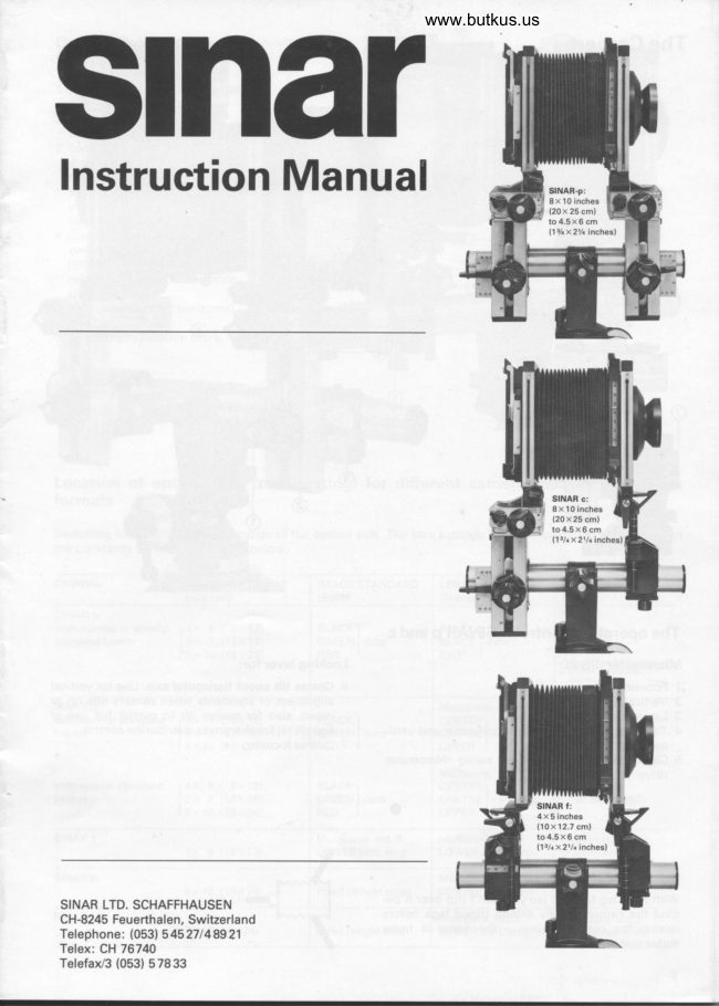
Sinar P / Sinar C / Sinar F User manual
User manual for Sinar P / Sinar C / Sinar F. 13 pages in English. Read the original PDF, download or print a copy without registration.
13 pagesEnglish4.6 MB PDF
Loading your manual…Open PDF directly
Document details
- Brand
- Sinar
- Model / document
- Sinar P / Sinar C / Sinar F
- Document type
- User manual
- Language
- English
- Pages
- 13
- File size
- 4.6 MB
- Category
- Film cameras
- Document date
- Not specified in catalog
Search available document text
Find a term, then jump to its page in the original PDF. Image-only pages may not be searchable; check the PDF for exact wording and diagrams.
Page 1 · Read text
www.butkus.us
$narInstruction Manual


 SINAR LTD. SCHAFFHAUSEN
 CH-8245 Feuerthalen, Switzerland
 Telephone: (053) 545 271 48921
 Tefex: CH76740
 Telefax/3 (053) 57833
View original page 1
Page 2 · Read text
The Cameras


                                                          www.butkus.us


 The operating controls: SINAR p and c
 Micrometer drives:                                Locking lever for:
 1 Focusing                                6 Coarse tilt about horizontal axis. Use for vertical
 2 Vertical displacement                                  alignment of standards when camera tilts up or
 3 Lateral displacement                              down, also for coarse tilt to permit full use of
4 Tilts and swings around the horizontal and verti-           fine tilt (4) for sharpness distribution control.
    cal axes                                7 Coarse focusing
5 Changeover lever for tilt or swing micrometer
   drive


 Set up the tripod right
 With third leg to front (so you don't trip over it be-
 hind the camera). Fully extend tripod legs before
 raising the centre column - the setup is more
 stable that way.


  2
View original page 2Page 5 · Read text
Mounting the camera
                     O Release the clamping lever A (move it against arrow). Fit the
                                       camera and tighten the tripod screw finger tight.
                                     Turn the locking lever in arrow direction to secure the
                                          camera firmly.
                          o To adjust the lever lock, unscrew the centre screw with a
                                                coin, pull off the lever and refit in the position required.
                                            Secure again with the screw.
                          o Releasing the knob B six to seven turns allows movement of
                                         the camera forward and back or about the base rail for
                                                rebalancing, also instant fitting and removal.
                                                      Rail clamp also takes the universal camera holder No. 519.11
                                            (See SINAR System Handbook, page72l.


                               Turning the camera
                                To turn the image frame for intermediate positions between
                                           upright and horizontal views, rotate the whole camera about
                                         the rail. Unlike the use of a rotating back, this keeps all swing-
                                                      and-tilt axes correctly aligned with the image axes. Turning the
                                    camera about the rail in this way also carries the lens hood
                                           with  it, and avoids vignetting in the image corners. (For chang-
                                           ing from vertical to horizontal shots however switch the back
                                          round through 90".)


                             The spirit levels
                                   To read the spirit levels accurately, centre the eye above them.
                                        This involves viewing with one eye; the rear line of the refe-
                                           rence mark must appear exactly behind the front line.
                                        Realigning the spirit levels:
                                                                            lf in time these should go out of adjustment you can easily reset
                                  them by fully releasing one screw and slacking off the other.
                                              Carefully realign the spirit level and retighten the screws.


                            The base rail
                                 The 30 cm (12 inch) base rail No. 422.11 with screw caps at
                                       both ends is part of the basic camera. lt is a standard compo-
                                          nent of all SINAR cameras. Extension rails screw to either end
                                                to make up any required length.

                                     F;;!Rt
ml                                           f*r
View original page 5Page 6 · Read text
www.butkus.us
Changing components
When switching camera backs (from 9x12cm or 4x5 inch|
bellows, lens board etc. always push in upright from above,
then lock.                            II

The locking lever signal
Fully close the locking strips with the lever down flush, to avoid
 light leaks.


The folding bellows
The folding bellows should not sag. So never place anything
on them.
From time to time fit the bellows switched round through 180'
about their axis.
The wide-angle bellows
With short camera extensions always take care to pull the wide-
angle bellows fully out from between the camera standards.
Otherwise you may not be able to push the latter fully together,
thus obstructi ng infi nity focusing.
Extreme tilts at short extensions
Special effects sometimes call for extreme tilts with short focus
lenses. These are obtained by swinging the standards about
the vertical axis V.
Depending on the location of the subject, the camera may have
to be turned round through 90o on the rail clamp.
The bellows lens hood

See SINAR System Handbook, page 58/99.

Filter holder and lens hood

These are attached to the filter holder rod as shown. By swing-
ing outthe filter holderthrough 180'to stop (1)you can direct-
ly adjust and check the effect (2) of the polarising  filter; then
swing the filter holder fully back in front of the lens.


For correct end positions, the red dots must match on the
coupling frame and on the filter holder.

Filters

See SINAR System Handbook, pages 74-75.
View original page 6
Page 7 · Read text
Ghanging the camera format SINAR p and c

                                        Detach the bellows from the lens standard. Release the format
                                       frame by turning the knob F anti-clockwise. When changing the
                                          format, recentre the optical axis on the rear standard 5earer.
                                             This is colour coded* and carries click stops.
                                             * Black : 4x 5inch/ 9xl2cmformatframeffinn,                                        Green : 5x 7 inch/13 x 18 cm format frame
                        Red : 8x 10 inch/18 x24 cm format frame
                                       See also table on page 3.
  -IIrr    H     t+rAqr.F       i:t' **
                             The specialstandard bearer SINAR p and c
                                   The special standard bearer has an additional locking knob V'
                                      to lock the swing about the vertical axis (for instance when
                                               setting up the camera vertically in conjunction with large format
                                               frames). Release this locking knob before adjusting camera
                                     movements, otherwise the micrometer drive turns without ef-
                                                        fect.


                             The 4x 5 inch / 9x12cm back
                                  Remove the ground glass screen frame by pressing down the
                                  two lateral spring latches and pushing the frame upwards. The
                                                   lateral locking strips on the film holder frame, which are now
                                               accessible, help to secure the different film holder types, espe-
                                                     cially roll film, film pack holders, etc.
                              When using the Polaroid film pack No.405 for horizontal shots,
                                   unscrew the lateral cover strip on the format frame and fit
                                           instead a replacement strip No. 431 .21.691.

                                The latch
                                      on the ground glass screen frame secures focusing accessories,
                                     such as the bellows with or without binocular magnifier, or the
                                                                     bi nocular reflex mag nifier.
                                       Fresnel lenses, ground glass screens, masks
                                    See SINAR System Handbook, page 60.
                              Automatic film holder/shutter coupling
                                   The SINAR backs carry a coupling socket for automatic shutter
                                           operation via a cable linkage between the camera back and the
                                   SINAR shutters.
                                          Mechanical SINAR shutter   :
                                 Once the bayonet connector No.521.91  is adjusted, screw  it
                                                 tight on the back and leave it there. That permits rapid switch- 521sl                                                ing of the automatic cable without readjustment.
                                             Electronic shutter:
                                                                                                                                              in                                The automatic cable needs no adjustment - just screw it
                                                          fully.   t
View original page 7Page 8 · Read text
www.butkus.us
 Lateral displacement when using the automatic film holder
coupling SINAR  f :
When the automatic cable is fitted with the film holder upright                      r'n (and you want to shift the back to the right, carry out this adjust-                                                 n.ment by moving the lens standard to the left (and not by mov-
 ing the back to the right). Alternatively, use the indirect parallel
displacement (arrow).

                                               *
                                                                                                           t-

The Rapid Adaptor
Can be used with lenses from 90 mm up on the SINAR p and c.
On the SINAR f reverse the camera back (image standard)
through 180' as shown. Can be used with lenses from 135 mm
 up.
 For further details see separate instructions.
The depth of field scale
See summary instructions enclosed with every camera. See
also page 80 of the SINAR System Handbook.


                                                 Mike Butkus             Digitally                                                                                                                                                                                                                                                                                    DN:email=mike@butkus.org,Date:cn=Mike2021.09.19signedButkus,by12:23:10Mikeo=ButkusButkusc=US-04'00'camera manuals, ou=butkus.org,
Double sheet film holders
These are easy to load. However, please note:
O Always push sheet films fully into the bottom to avoid loss of
  sharpness and light leaks.
O To ensure optimum film flatness store the films in a dry
   place. Considerable temperature changes have to be avoided.
O After withdrawing the film holder slide, gently tap the focus-
   ing screen to release any stresses in the film.
Otherfilm holders
See SINAR System Handbook, pages 65-69.


Transport
SINARf
SINAR f camera models (from Serial No. 19761 on) fold up as
shown in the illustration. Preferably leave the rail clamp on the
tripod. The camera then fits in any popular executive-style
briefcase of suitable size.
SINAR p or c
Before stowing the camera in case 475.26 or 475.42, the 2
camera standards have to be moved together until the two red
points on the center piece of the basic rail unit 422.11 are visible.
fn this position the camera  fits easily into case 475.26 also with
behind-fens shutter 521.31 or into case 475.42 with shutter
522.11 and/or lens up to 240 mm focal length.
View original page 8Page 9 · Read text
The multi-purpose standards: SINAR p, c and f

                        The multi-purpose standard  I
                              This is the lens standard of the convertible camera as de-
                                   scribed on pages 25-26 of the SINAR System Handbook and
                                   also serves as a multi-purpose standard to extend the scope as
                            shown on page 58.
                        The multi-purpose standard  ll
                                  This also serves as the rear or image standard of the SINAR f
                                         (vertical position set to lowest engagement stop).  lt has a fine
                                focusing drive, depth of field scale and tilt angle scale but no
                             opening collar. With its fine focusing drive this standard can
                                     also serve as an object stage for close-ups and macrophotogra-
                                  phy. (See also SINAR System Handbook, page 58.)

                              Depending on the camera combination used, adjust the vertical
                                  or lateral shift to the appropriate engagement stop or marking
                                      to centre the optical axis. See table on page 3.


                                    Raising the standard: Slack off the clamping screw and push
                                             up the columns with the fingertips as
                                              shown in the first illustration  left.
                               Lowering the standard: See second illustration  left.


www.butkus.us


                              With the coarse adjustment clamping screw fully unscrewed
                              you can open the hinged collar of the multi-purpose standard    I
                                      to change the standard without dismantling the camera.


                          To adjust the tightening force of the clamping levers on the
                                multi-purpose standards unscrew the screw with a coin, pull
                                    offthe lever and refit on the shaft in the required position.
View original page 9Page 10 · Read text
www.butkus.us
Better focusing yields better pictures


The best camera, the best lens, optimum resolving power and
utmost film quality still depend entirely on focusing precision.

Better focusing

See SINAR System Handbook, pages 60-62.

The camera position

See SINAR System Handbook, page 38.

Setting up the camera
Before starting to use any seftings, set all movements to their
zero position or engagement stops. (O indicates the film plane
location on the SINAR p and c).

SINAR p and c: Set the changeover levers for the swings and
tilts to the same position on both standards (i.e. both at V or
both at H).

Direct parallel displacement*

For short extensions; use wide angle bellows if necessary.
O Set up the camera in its basic position as shown.
O Centre the image with the rise and fall or lateral shifts.

Indirect parallel displacement*

For long extensions, bellows hood and for large shifts.
O Point the camera at the subject as shown.
O Bring the standards back to vertical with the coarse  tilt (ar-
   rows).
* Verticals are reproduced parallel when the image standard (film
  plane) is parallel to the object. (Lens standard adjustments do not af-
  fect perspective, only sharpness distribution).

Parallel displacements See SINAR System Handbook, pages 81-83
The swings and tilts    See SINAR System Handbook, page 89
Perspective control    See SINAR System Handbook, page 90
Control of sharpness
distribution            See SINAR System Handbook, page 95
View original page 10
Page 11 · Read text
Creative and corrective sharpness
distribution control

See SINAR System Handbook, pages 90 and 91.
Sharpness distribution controlwith the SINAR p and c
by two-point setting
(Always adjust this before stopping down the lens.)

With the image standard
(camera back) - modifies plane of maximum sharpness and
perspective:
O Set the standard vertical with the coarse tilt adjustment.
   Slack off lever 3.
O Set the H/V changeover lever for the micrometer tilt on both
   standards to H (or to V for swings about the vertical axis).
  1 Sharply focus a suitable first image point* on the horizon-
       tal axis H with the fine focusing drive 1 (or a point on the
      vertical axis V for a swing about the vertical axis).
  2 Turn the micrometer tilt drive 2 to focus a second more or
      less opposite image point within the shaded area sharply
     on the ground glass screen. That is all

With the lens standard
modifies only the plane of maximum sharpness, but not
perspective:

   Adjust the sharpness distribution as above first by tilting the
   image standard (camera back). Read off the tilt angle on the
    scale. (Direct tilting with the lens is not suitable as for optical
   reasons the overall plane of sharpness always shifts.)
   Then transfer the tilt angle read off the scale to the lens
   standard as follows:
    a) Transfer the tilt angle obtained to the lens standard in
      either positive or negative scale direction by turning tilt
     knob 2.
    b) Reset image standard to zero position by turning  tilt knob
     2 (engagement stop).
   c) Refocus with the focusing knob 1 for maximum overall
      sharpness. Adjust the image standard as described above
      to eliminate final residual deviations.
* For off-axis image points repeat the focusing sequence 1-2 to elimi-
  nate the deviation.


Lens tilts with close-ups
With close-ups (subject distances below about 5 times the focal
length) any lens adjustment introduces further problems by
modifying both the subject distance and the lens/image dis-
ta nce.
Here it is better to use the rear or image standard for sharpness
distribution control. lf you still want to tilt the lens standard,
adjust the lens tilt first by visual sighting as shown so that
planes of the subject, lens standard and image plane meet in a
common axis. Then carry out final adjustments on the image
standard.
View original page 11Page 12 · Read text
www.butkus.us
Sharpness distribution controlwith the SINAR f
by two-point setting
(Always adjust this before stopping down the lens.)
Measuring the tilt angle
O Set the angle scale exactly to zero - see diagram - with the
   fine focusing drive of the image (rear) standard.
  1 Use the coarse adjustment to focus a suitable first image
     point sharply on the horizontal axis H. Do not move the
     fine focusing drive. (Or use the vertical V axis for swings
     about the vertical axis).
  2 Turn the fine focusing drive to focus sharply on a suitable
    second image point on the opposite axis at H' (or V') as
    shown in the diagram.
  O Read off the tilt in degrees and the tilt direction (* or -)
     on the angle scale* (example in diagram: +12'l..
Set this value (12' in the example) and direction (t) on the
standardxx to be tilted, using the corresponding  tilt scales as
shown in the diagrams.

O Refocus for maximum overall sharpness.
For off-axis image points or with an inclined camera repeat the
focusing sequence 1-2 (H-H' or V-V') to eliminate this devia-
tion.
  * lf the range of the angle scale is insufficient.  set up an approximate
   preliminary tilt of the camera back for convergence of the image,
    lens and subject planes.
** Tilting the rear or image standard modifies both the plane of maxi-
  mum sharpness and perspective.
    Tilting the lens standard modifies the plane of maximum sharpness
    but not perspective.
Focusing off-axis image points
See SINAR System Handbook, page 95.
Gombined sharpness control and stopping down
See SINAR System Handbook, page 96.

View camera lenses
See SINAR System Handbook, pages 32-46.

                                     -0__i


Closer shooting concentration - even with the view camera
See SINAR System Handbook, pages 47-54,139.
View original page 12Related documents and language editions

SinarPDF
SINAR
User manual
29 pages · EnglishRead →
SinarPDF
Sinar - Advantages of yaw-free camera
User manual
5 pages · EnglishRead →

SinarPDF
Sinar Camera
User manual
20 pages · EnglishRead →

SinarPDF
Sinar Code booklet - 1981
Product booklet
24 pages · EnglishRead →
SinarPDF
Sinar Copal Shutter
User manual
10 pages · EnglishRead →

SinarPDF
Sinar F
User manual
18 pages · EnglishRead →

SinarPDF
Sinar F Operating Instructions Color
User manual
8 pages · EnglishRead →

SinarPDF
Sinar P
User manual
59 pages · EnglishRead →

SinarPDF
Sinar Code Booklet
Product booklet
27 pages · Not specifiedRead →
From the M. Butkus archive. Original publisher and archive notices are retained.
Check the model and edition against your equipment.
PDF verified 2026-10-10.