Film cameras
SINAR User manual
User manual for SINAR. 29 pages in English. Read the original PDF, download or print a copy without registration.
29 pagesEnglish2.8 MB PDF

Loading your manual…Open PDF directly
Document details
- Brand
- Sinar
- Model / document
- SINAR
- Document type
- User manual
- Language
- English
- Pages
- 29
- File size
- 2.8 MB
- Category
- Film cameras
- Document date
- Not specified in catalog
Search available document text
Find a term, then jump to its page in the original PDF. Image-only pages may not be searchable; check the PDF for exact wording and diagrams.
Page 7 · Read text
f
                                                                                                                  5-r'3r.r-3      Close one eye when readlng tbe eplrit  level.  To adjust  it correctly,   the centre must be viewed
13           directly   tiom  above. You have the correct  readlng  angle when the rear  stroke  mark  coincides  with
               the front  one.

            The horizontal   spirit  level on the rear  carrler  has to be set  elightly  off centre,  with te bubble appro-
               ximately   in the middle  of the right  hand mark.  Tightening  the locking  knob of the bench holder  No. x 100,
            an accurate  tine adjustment  is then posslble.??F?Fe       Changing formatsl
F3        For  interchanging  formats  between 4/6n  lS/Lz,  arrd Shtt  (1g/18) see fig.  5.
F?           Before changing over,  always securely  tighten the rise-and-tall   adjustment knobs.a
?na        The 8/10tt {LS/24I back requires  changingthe  entire  rear assembly  includingthe   carrier  clamp.


              Every tlme the bellows are changed, make sure the sliding  locking  clips are right home.?F3


              Monorail   optical  bench:
            The 18 in.  long optical  bench unit can be eubdivided  to glve more  efftcient  wide-angle  performance,
            and inerease the handiness of the eamera.  The part designated No. x 210/30 cm (12tt) for the
                                                                                                                          peircils,  etc. ??????n       STANDARD  is hollow and serves as a receptacle  for  articles  such as flash cables,
             There  is an insert  in the front end-cap No. x 230, which accepts the scale No. x 240 and a filter
              holder rod No. x u40   (iig.  ?).larc
7          Thescrewedextensionto the benchSTANDARDunit No.benchx 2LO/L5unit No.(6t) xhas2L0/30,a rotatingextendingaxial itrodtowardsunit,  whichthe rear.enables  it to beFID

            The 15 cm  (6tt) bench unit can be uged as a base for  the SINAR STANDARD  by itself.   For  this reason
               the rear  end cap No.  x 220 ca.n be screwed  on {press  forward   slightly  on the rotating  rod  to prevent
               the cap turning  whilst  screwing).nnFV'
n,
E
YA
L4
b
n't
)a
n
F S
4.,
. ,
n
fr
J4
2a
?a                              www.butkus.us
View original page 7Page 9 · Read text
n
l'3
              Securing the  filter  and bellows-holdert
               This  is done with  the  filter  rod No. x 1140-11  or -16 on the front  frame.  When inserting     it make surenhre          the red dots coincide.n
rc         The  filter  holder  No.  x 1120 can be Ewung out through  180o in order  to adJust the polarizing    filter.

              For  applications  eee figs.  ?,  8, 9 and 10.hn
?14        The rubber  bellows No. x 570 can be used either as a eimple lens hood, or as a light hood for the
)4            4/5  ln. back. When  it  is positioned  for viewing the focusing screen  (figs,  8 and 10), the use of
?lt         EKTALITEenough for  centrallens No.viewing.600 E is(Fotstrongly5/7  in.,recommended,No. 1680 F.) so aB to make the corners  of the image bright
)4
           Camera Backs3rc
            The SINAX backs are  primarily   designed  for  the most commonly  used American  type double  film-rc         and plate-holders.    Film  holders  for  the corresponding   centimetre  and inch formats  with  the identical
)4           exteriordimensions   can be used interchangeably  in any one back.

                                                           9/tz  cm  arid 4/Et,nrc                                                13/t8 cm arLd,Shtln                                             18/24 cm and 8,/10'l

            The SINAR 4/5 back No. 600 KM accepte  the followiug  othermnnufacturerst     accessorleet)4n                           -  GRAFLEX  light hood for focusing screen viewing,  No. 914?))a                       -  POLAROID  4/5  film  holder  No. P 500. To secure  the heavy holder  in the plane,  use the two
rc                      eliding  clips on the SINAR plate-holder   carrier  No. 600 K.
rc           So-called  trMlllonn  plate holdere  can be usedt see page 11 below.

               After removing  the focusing screen frame,  the following GRAFLEX  and LINHOF  accessories  cann)-a
H'            also be fitteds
V'                           -  RollfilmholderstGRAFLE(   2r/4x2V4in.   No. 1251, or 2t/4xB  in.,  No. L244t,also
n                       pictures.LINHOF  2 (Ther/4 x simplest2 3/4  in. waySuperof Rollexusing rollfilmZRN,  foror 10for pictureswide-angleor CinepicturesRollexon ZRCNrollfilm.for ) 50
l.a                         -  POLAROID  rollfilm   adaptor No. 9108 with GRAFLEX  focueing screen No. 9288 and GRAFLEX
F                           light hood No. 9146.
                                       rtGraflargertr  Coldlight  Enlarger  Attachment No. 6019 with accessories.n                            -  GRAFLEX
))t                          -  GRAFLD(   t'Dividing  Backrt No. 9109 for 2 pictures  on 1 film  4/5.
)-tt                          -  LINHOF  Police Adapter 6 x 13 cm No. YZTP  and LINHOF  enlarging  attachments,  cold-light
                   YTKN,  condenser YTKV.
                                -  Fresnel  lenses which are supplied ready-cut  from SINAR, under No. 600 F for 4/5  (9/L2l and)4n
4                    No. 1630 F f.or 5h  (13/18).  These are mounted between the seating area for the focusing
>c                   .       andscreenmatteandsurfacesthe screenfaceitself,each withother.theTheysmoothare sidesent ofin thethe lenscameraoutwards,back 4/5so (9/12)that theNo.grooved600 M
                                                            in the camera backS/7  (13/18) No. 1630 according  to fig.  11a. Thesa                  according  to fig.  11 and
€                     Fresnel  lenseg bought by SINAR are cut in a way that the focus  shift  of about 0,5 mm resul-
4                         ting from  the use of these lensee is necessarily  corrected.
)rte
4
4
fr
4
>.n
||-
?a                              www.butkus.us
View original page 9Page 11 · Read text
F
FF"       Revolving  Back!  wtth the SINAR,  thts  factltty   ls obtalned  by swinging  the entlre  camera   (fig.  12).
            This ensures that the movements  maintain  the eame relationship  to the image axis.  Furthermore,   the
             backlight  protection  hoods or bellows swing with the camera,  and moreover,  the edges of the image
           remain  fully  illuminated  without having to increase  the volume of the camera.

           Swing principle.  The SINAR possesses a swing principle  of its own.  It unites the centre-swinging
            advantages  with  the great  range and the wide-angle  capacity  of base swinging.  The manipulation   of the
          SINAR swing principle   is recommended  as shown in  fig.  13.

          When the camera   is very much  lnclined  and a combination   of vertical  and horizontal   swinging  is made,
             there can arise  disturbing  deviations  of the frames  from  the vertical  axis.  {Tilt  movement}.  These can
           be avoided by fixing  the camera on the tripod,  according  to fig.  14. (Monorail  optical bench aside thePF?FF?aF
           camera.  )

                                                                                 (fig.  15). By means of moveable magks h  the coupling
            frame  {these are supplied with 8/10 (18/241 adaptor) the formats  can be divided  into two or four parts.Fnts            With this system   it needs to be re-set  for each picture  position.   If you wish to avoid this,  you may set
            a cover mask on one side of the coupling frame.  After  the first  picture,  the camera back is swung
             through  1800 and the second picture  can be made without  needing  re-setting.

            Another  possibility   is to insert  a format  reducing mask into the compendium and then to begin the
             subdivision by displacing  the camera back.

           The 8,/10 in. back can be used either  with normal  negative holders  or with special holders  for colour
             separation  or test exposures.  For the latter  the bearing points are adjustable  (fig.  16).
                    Position   I    =  normal,   for commercial  negative holderg????FF?Fn                Position  2   =  Multicolor  8/10  in. Focusing screen  lies  directly  on the bearing points. SINAR
L4                                   Multicolor  Holder No. 2200 with  insert No. 2230 should be used.
)4                 Position 3   =  Multicolor   L8/24 cm.  Focusing screen  lies directly  on the bearing  points. SINAR
F)                                   Multicolor  Holder No. 2000 with  insert No. 2220 should be used.
v4,       The adjusting  pin marked X  is adjusted  with  sufficient  accuracy  when supplied.

                       It should not be altered  except  in caee of necessity.En
F         The bearing member,  however,  can be adjusted simply by loosening screw )O( with a coin.  (Loosen  it
                sufficientty   to free   it from  the guide pin provided  and re-set    it).n
n          For color-geparation  work the frame  stabilizers  No. L870/L875 should be used (see fig.  38).
",
F
           When inserting  the negative-holder-focusing   screen framee  for 5/7  in. (13118) and 8/10  iL.  (L8/24',an              into the camera  body,   it  is important   to check that these components  are  inserted  into the appropriate
                                                                                             light may leak  in.r4          grooves before the catch is released,   If this  is not done,
7,
)4
€
4
4
4
a)
a
E
a
a
E
-€                                www.butkus.us
View original page 11Page 13 · Read text
Negative Holders3
         The American  double negative holders ueed with the SINAR are very easy to load,  but remembert

                          -  Sheet film  must always be pushed  ri.ght home  into the holder,     i.  e.  until  you feel   lt come to
                   a positive  stop.
                          -  The back of the film  will  be ecratched when there are dust particles  between the back of the
                         film  and the negative  holder.
na      For plates 4/5  - 8/10  l^.  (18/24  crn) there are specially made plate-bolders  available.
rc                   It  is advisable  to store  the negative  holders   in their  case with  the slides  pointing  downwards,  so thatn        the films  cannot slip out of their  grooves and the slides cannot come out in transit.
)4
l'14
         Remember3 American  negative holders  4/6 and 9/t2  on the ASA system and certain European manu-rc        factures  of this format show slightly  different  focusing-planes.  A small  correcting  plate can be laidrc       under the ground-glass  for European models.  This plate  is supplied on request.
re
         Thg Multicolor   negative  holder  can be provided  with  interchangeable   adaptor  inserts   for  8,/10 i:1. and
                       plates.  These inserts  canbe removed  for  loading,  although this  is not absolutely neeessary.nn       18/24cm
)4
n        designedFor color-geparationfor plates.   work and test e:rposures,  plates muet be used. The Multicolor  holder  is therefore
fr
                                                                                                guides                                                     holder,                                                                        transparencieg                                                                               ag                                            is                                                                    colour                                                                                               colour                                                                                                                                  for  color-                  If,              despite this,                                  film                                used with the                                                                       {e.  g.n                                                                                   film                                                                                        insert.  This  is                                                                                                                   fitted                                                                                                                into                                                                                                         the plate                                necessary                                                      to use                                                        it  is                                                  a special                                                             sheet           separation                       work),24        with  its closed short side facing the dark  slide,  so that the film  cannot rise up and catch on the slide,holder
)4
14      When uslng the Multicolor   holder,   the back must be re-sett  see under  A/fO  h.  back,   fig.  16.
|4
                                                                                                                                                                              't x 4 3/4  tt, whereas then       POLAROIDthan 4/s.  TheP500normalholder4/54/5.sheetThefilmugableholderareagivesof polaroidan actualnegativearea of in3 the3/4 P 500 holder  is  slightly  less
34         polaroid  is 3 t/2 rt * 4 r/2 tt. On the SINAR ground glass screen this occupies the approximate  area as
;4          the 9 x 12 cm.  marking,  within about 1/8".
n
n
14       Numbering  stencilsl
)4          stencils,Tlne L8/24whichcm {exceptphotographMulticolor}the negativenegativeholderholdernumbermade inforromanSINARfigurespermit onthetheuseedgeof numberingof the  film.    It
n            is also eaeily posoible  to change these stencils and employ oners own markings,    i.  e.,  for  color and
)4         black and white.  When exchanging  stencils,   take care not to bend them,  otherwise  there  is a danger
J4         of light  leaks.
                metal  'rMlllon"  negative holders can be ueed with the SINAR 4/5  - 9/L2,  and 5h   -  13/18 backs,n        Sheet
)4        provided  that the Linhof intermediate  frames,  YZZN  for  9/lZ  andYZZD   for 13lt8  or YZZF  f.or LO/L5
)4        areis placedused. intoThe thesheetcamerametal back.holder  is  first  slid  into the intermediate  frame and then the whole assembly
34

)4
)4
n
)4
n
14
;4
1                               www.butkus.us
View original page 13Page 15 · Read text
4
4
4
4a       Folding the camerag  fig.  17
4       Remove the lens and the filter-holder    rod.
           With the 5/7  i^.  (L3/L8  cm) carnera,   sllde  the rear  standard  approx.  r/2 in. upwards  before  folding.4,a
4         theWiththeS/10in.standards  to their(L8/24outermostcm)camera,stops beforefolding,and re-lock  them.looeenthecoarsefocusingadjustments,Set the micro-gear    to zero and then loosenslide
4          rise-and   fall  adjustment  on the  front  standard.

          The height  of the optical  axis  is marked  by two stops on the front  standard.  The lower  stop indicates
            the optical  axis  for the format-changing  adaptors 4/5  (9/L2l  and,5/7 (13/18),  and the upper stop for
            the format-changing  adaptor 8/10 (18/24).


          When unfolding,   take care  that the bellows  are  correctly  hung and locked! Qaaaaaaa        Maintenance!
            Just  like a car,  a technical  camera  requirea  regular   careful  maintenance.nn                A                                          should be cleaned with petrol  from time  to time,  and lightly  greased          The points indicated thus A
            afterwards.  The same proceeding  is recommended  for the threaded spindle of the pan-tilt  head x980,
          and the parts  of the universal  clamp x950 an x960.


          Clean the micro-gear   with petrol.    If necessary,  loosen the 3 ftxing screws on the longitudinal  side
             of the guide rod with acetone,  re-set  the slides and secure with clear  lacquer.  Grease  lightly.

          To this instruction  booklet  is attached a tin of suitable permanent  grease.  This grease should be?????nrc       very  lightlylaid  on with a brush,  so that there  is only an emulgion  coating.
FFn
n          With such care,  the working  life  of your camera  will be considerably  extended.
n
n
fr
4l
F
E
En
,a
a
E
a
n
a
E
E
F
a
E
,6                              www.butkus.us
View original page 15Page 17 · Read text
l--?F"


                                   THE SINAR EXPERT

                                                                            of the following  accesgoriee3hF     By extending  the SINAR STANDARD  with  the aidr"
                         -  wide-angle  bellows
                         -  monorail  extension,  18 in.  (45 cm),  x 2L0-46
                         -   auxillary  frame,  x 400
                         -  square bellows,  x 530
                         -  magnifier,   x 850
                         -  matte box and filter-holder   rod, x1140-11  or -16FEFE              -  bellows holder,  xl1.50, etc.
FF         you attain  the ultimate   in versatlllty   and efficiency.   Apart  from  the wide-angle  bellows,  which  differs
             according  to the format,  the accessories  marked  with x can be used with  all SINAR format-adaptors,
               effecting  a great  saving  in both time and money.HVa
            The SINAR EXPERT  permits  the following  combinatione:

           Use of wide-angle  bellows
             For wide-angle  photography,  and considerable uee of movements  at short extensions  (fig.  19).

            As a focuslng  aid tn conjunction  wlth  the magnifier    (fig.  20).hEE

            Long extensions
             Bellows extension with aid of monorail  extension,  auxiliary  frame and square bellows  (fig.  2L). (SeeFEF            also under ?rlong extensionsft page 21 and fig.  28).
)'A
            The monorail  units  of the SINAR EXPERT  consisting  of the 12 in.  (30 cm),  6 in.  (15 cm) and 18 in.
              (4b cm) NORMA extensions,  permit  a convenient graduation  of the base length,  divided  at 6 in.  inter-Fn
fr              vals.cameraThisbasegivescan 6bevariationsextended asfromrequired.6 to 36 inches in length. By acquiring  further  extension units,  the
vo
n
?a            Attention!  Bench extensions (red tenon) may not be screwed together,  without having  first  screwed
             one in to a piece marked NORMA,  to provide  a rigid  axis.fr
,]a
Ere
A
€
lla
€
€
)'€
1
1
n
n
rt
F
4|*a                ',.":.--,:--,-:,,             www.butkus.us                                                          -      .;    :  r;!!ill-i:
View original page 17Page 19 · Read text
rc                                                                                                   L7
n)<
2?       The auxiliary  frame  ag a copving  etage
                                                               copying and macro-photography    is highly  convenient,F?       The use of the auxiliary   frame  for  small-scale
              achieving excellent  results  with modest equipment.  Fig.  22/23.

           A cold  light  attachment  can also be ineerted  in the auxiliary   frame  wtth the aid of the +/S  tn.  {9/L2  cml
             negative holder  frame,  No. 600 K.hrcrcrc

                                      light sources can impair  image sharpness.  Flash or daylight are both ideal sourceshn            Heat-reducing
                 of illumination   for macro-photography.
nrc
            As a stage for  larger  objects,  the coupling frame  of one of the larger  format-adaptorg   is recommendedre
                  (fig.  2a).n
?14        The use of the auxiliary   frame  and large  frame  ae a copying plane has the advantage over a copying
               table that  it can be tilted  to provide  the distance compensation,  6o essential  for focusing  in macro-re         photography.  Furthermore,   with thle arrangement  either  reflected  or transmitted   light can be usedrc         as desired.rc            The use of the main  frame  as a subJect plane hae the advantage  that the fine focusing  can be made fromre         the side of the subject,  which means that the image scale, once set, does not have to be changed anyn          more.
Fn
,4
F
,4
Eanrt
n
frt
4
rt
)a
E
F
Fe
?e
JA
q
2€rt
F
Fn
Frt
JA
;ta                              www.butkus.us
View original page 19Page 21 · Read text
F


          The Matte Box
          To permit  the adjustment  of the matte box at short  extensions,   the matte box bellows  are not gecured
              at the lens back end (ffg.  25).frhftl'"rc
na
              Fig.  26: Matte box for  long extengions.  By rotating  the auxiliary  frame  through  18Oo the extensionrc
           can be increased  stiU  further.7a


           The operation  of the matte box  is  sigrrificantly   improved    if the correct  format  masks  are  lnserted.nnn          (Order No. x 1050).
14
n
ft         By using masks,  multiple  exposures  and slmilar   trick  ehots can be made  (fig.  27).
n
n
na        For more  possibilities   of combination and completion  of the SINAR see also "SINAR Construction
                    prospectus.n              Unitil
|4
fi
l1'
fi
F-a
fr
fi
E
E
F
a
14
;qa
fr
;a
a
E
E
fr
fra
lt
;a
*a
ta
ta
F
a
3E'
F
]€
a                               www.butkus.us
View original page 21Page 23 · Read text
F"
?7

                                     VARIOUS COMBINATIONS

           Long extengions:
           The longer  the camera  extenslon,  the gteater  the need for  stabtltty.    It  ls therefore  recommended
              to fix the carnera  in such caseg with the aid of a second bench holder x 100 on two tripods.   (fig.  38)
            With very heavy tripods  two bench holders  x 100 are  sufficient,  being fixed on the tripod  with a base
              plate which can easily  be made by the photographer   himself.    (fig.  28).

            Extensions longer than 90 cm (36 inch):

              (Fig.  28) The mounting  of the camera  is the same as above.  If extensions longer than 90 cm (36 inch)fth-FEE are used,  the 5/7  - 13/18 rear  carrier,   No. L610, and the joint block No. 310H together with bellows
           No. 1650 have to be employed as a further  intermediate  element   if using the 8/10  - 18/24 size. As a
            connection with the back a special bellows No. 20?5 from  8/r0   - L8/24 to 5/7  - 13/18  is needed,  which
           can be supplied on demand.

             Specially large lens Panels:tsE
               (Fig.  29) The SINAR lens panels normally   supplied  are big enough for  all  standard  lenses  for  profes-
             sional cameras.  Yet  it may happen in very  rare  special cases that an even larger  lens panel is re-
             quired.  This combination  is poseible through using the rear  carrier  5/7  - L3/L8,  No. 1610, together
             with  joint block No. x310V as front  lens carrier.  Here too  it  is necessary  to use the special bellows
           No. 20?5 frombh     - 13/Lg to 8/10  - 18/24, as well as a special lens panel No. 810.

           Extreme  rise and fall movement:

         On extreme movement  of this nature,    it may happen that the bellows  or the back are vignetting.  To
            avoid euch special cases the whole camera would have to be built  larger  and heavier,  which would not
           be convenient.  However,  this additional movement can be made  if desired,   in the instance of the 4/5  -
              g/!Z  format,  by using  tb;e 5/7  - L}/Lg camera back with the reducing adaptor No. 1640, Similarly,
            withthe Sh   - Lg/I8 formatbyusingthe   8/10 -L8/24 camerabackandreducingbackNo.   2055, or forEEEE            4/5  - 9/12 No. 2060.

             Protecting  the camera  against reflections:

                 (fig.  B0) Cardboard glued to bellows frame,  Order No. 510-01, and secured to auxiliary  frame.

            Various combinations and completion  pogsibilities:
          See also ilSINAR-Construction-Unittr   prospectus.reFaEEE
)Q>a
re
)-t
l;l
)4
14n
a
n
>a
n                                www.butkus.us,.1;-  +^.;-:       ri;.                                                                                                                                                            . , . '    - .       ]       - !
View original page 23Page 27 · Read text
:
4
4|a
          Rapid-Adaptor  No. 620a
4          Fig.  34. Negative holder can only be attached  when dark  slide inserted.
4a        Observe careful  handling
a
a       Snap in  slide  fully  to right  against  stop
4
          Then:
aa          1. Push negative  holder  fully  to  lefta
             2. Press negative holder and adaptor together,  then negative holder  will   fall  into position.
aa
                                                                                                     is pushed in.a         Fig.  S5.Negative holder can only be removed  when dark  slide
a;e       Observe careful  handling
a
a        Press fingers  together and move in direction  of arrow.  Negative holder  will  then come free.a
         Movement  of track  only possible  with holder  slide removed.a
a       Acce gsories  to rapid-adaptor  eee IISINAR- Construction-Unittr  prospectus.
a
Q
a         Mirror  No. x 925 (Fig.  36 and 3?)
a       andThe withmirrordisplacementmay be usedwhenin frontusing ofnormal-focusthe lens,  withoutlensesrdisplacementIt will  not affectwhenusingthe focusing.short-focusThe lensesloss
a          of light  will  not be more than 370, at the most.
a
a         For wide-angle  exposures  the mirror   can be mounted behind the focusing  Ecreen.
                            magnifier  No. 852 (specially made for rapid-adaptor  620)a         Reflex focusing
                                                 be used together  with a light-gathering   lens,  for examplea       The SINAR focusing magnifier  should only
p        No. 630L or 660F.
€          Cleaning of both mirrors:
            With well-washed,  clean and soft dry  linen cloth and lens cleaner.a
a
2
p
la
a
2
I
a
a
Ja
a
a
a
a
le                              www.butkus.us                                                          :.i-l;::.-:.'.t.-     i'.;t:i
View original page 27Page 29 · Read text
-
a
4
4
4      Use of stabilizing  rods and clamping  joints No. x1870 aDd x18?5
4        Fig.  88. Use of frame  stabilizing  rods and clamping  Joints for colour  separations and test exposures.
           Fig.  Bg. The stabilizing  rods No. x18?0 can be used as extensions  to the front  standards,  enabling a
                   considerable  increase  in rising  front movement  in special circumstances.4rc
           Fig.  40. They can also be used in various  other combinations  for securing masks,  reflectors  orrc
                      diffusing  screens,  etc.rcna
)a
                                                                              ttSlNAR-Construction-Unittrn        The most important  combination  possibilities  are shown in the
           prospectus.n
l'14
nt
na
                                    gUARANTEE-n
|4        SINAR FACHKAMERA  BAU guarantees  this  apparatus  against  fuilure   arlsing  through  faulty
         workmanship  or material,   for a period  of 12 months from  date of purchase,  for cash or on
          deferred  terms.  During  this period,  the supplier  will  repair,   or  at its option,  replace any
           defective  part,  excepting lenses and shutters  other than SINAR shutters (which are covered
          by their  respective  makers' guarantees).nnnrc          Replacement   will  be made of parts  which prove  on examination   to be defective,  provided  suchn        defectiveness  is not as a result  of accident or negligence.

                                                                                           or modification   is madeftp       The guarantee will be rendered  invalid   if any gnaurLhorig$  alteration
            to the apparatus.rc
         Any apparatus  needing  service  under  this guarantee  should be sent, packed and consigned  carriage
             p"id,  to either  the dealer  through whom   it was purchased,   or to the main  distributor    for the countryfrp
                                                                             no responsibility   for damageF          ofarepurchase.chargeableTheto coststhe cugtomerof labour,by packingthe supplier,and carriageand the throughsupplier teacceptsimplementing  of this guarantee,
              in transit  to or from  the purchaser.ta
la
ftp
         SINAR policy  is one of continuous  improvement.   The right  ig reserved   at any time  to change prices,
            specifications and equipment without  notice.?-n
?a
la
ta
7a       Schaffhausen, November 1962
ra
>a
Y-a
F
F
nn
F
]4
I
p                                www.butkus.us
View original page 29Related documents and language editions
SinarPDF
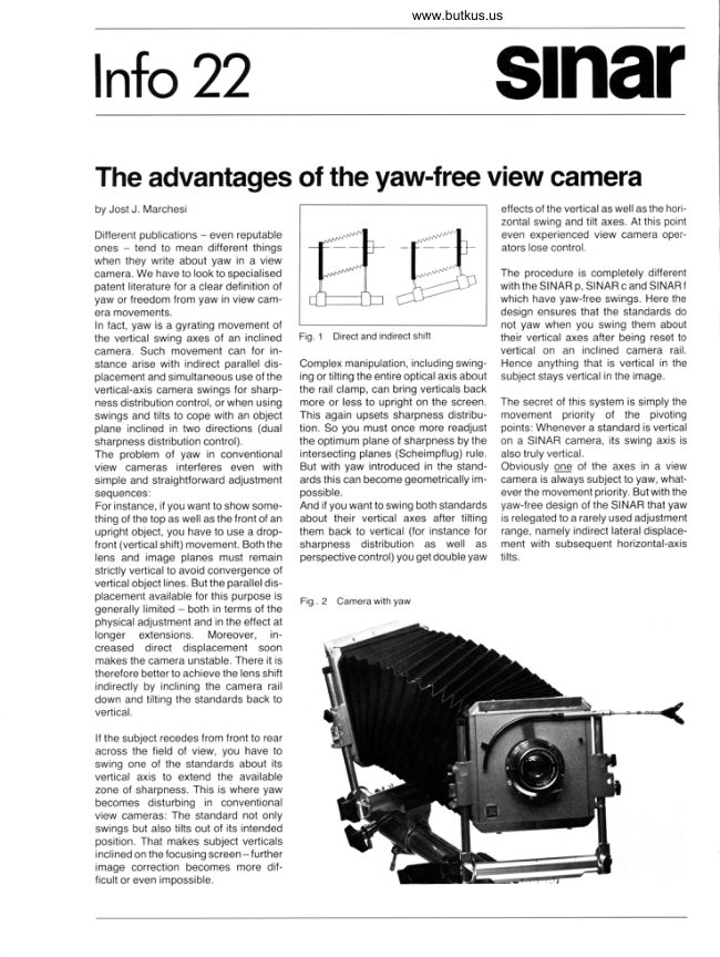
Sinar - Advantages of yaw-free camera
User manual
5 pages · EnglishRead →
SinarPDF
Sinar Camera
User manual
20 pages · EnglishRead →
SinarPDF
Sinar Code booklet - 1981
Product booklet
24 pages · EnglishRead →
SinarPDF
Sinar Copal Shutter
User manual
10 pages · EnglishRead →
SinarPDF
Sinar F
User manual
18 pages · EnglishRead →
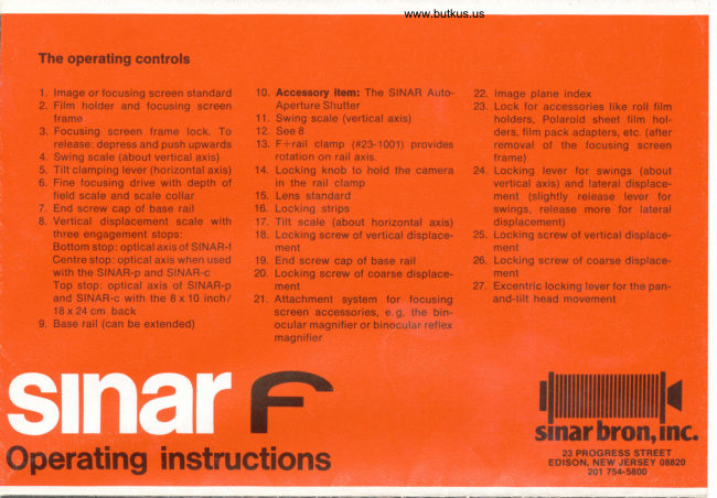
SinarPDF
Sinar F Operating Instructions Color
User manual
8 pages · EnglishRead →

SinarPDF
Sinar P
User manual
59 pages · EnglishRead →
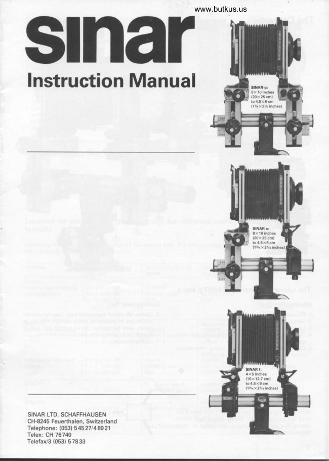
SinarPDF
Sinar P / Sinar C / Sinar F
User manual
13 pages · EnglishRead →
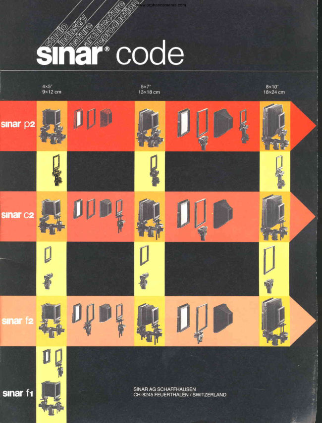
SinarPDF
Sinar Code Booklet
Product booklet
27 pages · Not specifiedRead →
From the M. Butkus archive. Original publisher and archive notices are retained.
Check the model and edition against your equipment.
PDF verified 2026-10-10.